

Page 1
ENGLISH User Manual
■
THERMO-ANEMOMETER
1227
DATA LOGGER
Page 2

Statement of Compliance
Chauvin Arnoux®, Inc. d.b.a. AEMC® Instruments certifies
that this instrument has been calibrated using standards
and instruments traceable to international standards.
We guarantee that at the time of shipping your instrument
has met its published specifications.
An N.I.S.T. traceable certificate may be requested at
the time of purchase, or obtained by returning the
instrument to our repair and calibration facility, for a
nominal charge.
The recommended calibration interval for this instrument is
12 months and begins on the date of receipt by the
customer. For recalibration, please use our calibration
services. Refer to our repair and calibration section at
www.aemc.com.
Serial #:
Catalog #: 2121.72
Model #: 1227
Please fill in the appropriate date as indicated:
Date Received:
Date Calibration Due:
Chauvin Arnoux®, Inc.
®
d.b.a AEMC
www.aemc.com
Instruments
Page 3

CONTENTS
PRECAUTIONS ..................................................................................................................................................................... 1
RECEIVING YOUR SHIPMENT ............................................................................................................................................. 2
ORDERING INFORMATION .................................................................................................................................................. 2
1. GETTING STARTED ......................................................................................................................................................... 3
1.1. Battery Installation ................................................................................................................................................... 3
1.2. Instrument Components .......................................................................................................................................... 4
1.3. Ins trument Functions ............................................................................................................................................... 4
1.4. Turning the Instrument ON/OFF .............................................................................................................................. 5
1.5. Function Buttons ..................................................................................................................................................... 5
1.6. Display .................................................................................................................................................................... 6
2. SETUP ............................................................................................................................................................................... 7
2.1. DataView Installation ............................................................................................................................................... 7
2.2. Connecting the Instrument to a Computer ............................................................................................................... 7
2.3. Instrument Date/Time .............................................................................................................................................. 8
2.4. Auto OFF ................................................................................................................................................................. 8
2.5. Temperature Units................................................................................................................................................... 8
3. STANDALONE OPERATION ............................................................................................................................................ 9
3.1. Making Measurements ............................................................................................................................................ 9
3.1.1. Air Speed ...................................................................................................................................................... 9
3.1.2. Air Flow (Volume) ......................................................................................................................................... 9
3.1.3. HOLD Function ........................................................................................................................................... 11
3.1.4. MAX AVG MIN Function ............................................................................................................................. 11
3.1.5. MAP Function ............................................................................................................................................. 11
3.2. Recording Measurements ..................................................................................................................................... 12
3.3. Errors .................................................................................................................................................................... 12
4. DATAVIEW ...................................................................................................................................................................... 13
5. TECHNICAL CHARACTERISTICS ................................................................................................................................. 14
5.1. Reference Conditions ............................................................................................................................................ 14
5.2. Electrical Specifications ......................................................................................................................................... 14
5.2.1. Temperature Measurements ...................................................................................................................... 14
5.2.2. Air Speed Measurements ........................................................................................................................... 14
5.2.3. Air Flow Measurements .............................................................................................................................. 14
5.3. Memory ................................................................................................................................................................. 15
5.4. USB ....................................................................................................................................................................... 15
5.5. Bluetooth ............................................................................................................................................................... 15
5.6. Power Supply ........................................................................................................................................................ 15
5.7. Environmental Conditions ..................................................................................................................................... 15
5.8. Mechanical Characteristics ................................................................................................................................... 16
5.9. Compliance with International Standards .............................................................................................................. 16
5.10. Electromagnetic Compatibility (CEM) .................................................................................................................. 16
6. MAINTENANCE............................................................................................................................................................... 17
6.1. Cleaning ................................................................................................................................................................ 17
6.2. Battery Replacement ............................................................................................................................................. 17
6.3. Firmware Update ................................................................................................................................................... 17
REPAIR AND CALIBRATION ............................................................................................................................................... 18
TECHNICAL AND SALES ASSISTANCE ........................................................................................................................... 18
LIMITED WARRANTY .......................................................................................................................................................... 19
Page 4
Thank you for purchasing the Thermo-Anemometer Data Logger Model 1227. For best results from your
instrument:
read these operating instructions carefully,
comply with the precautions for use.
WARNING, risk of DANGER! The operator must refer to these instructions whenever this
danger symbol appears.
Information or useful tip.
Battery.
Magnet.
The product has been declared recyclable after analysis of its life cycle in accordance with
the ISO14040 standard.
AEMC has adopted an Eco-Design approach in order to design this appliance. Analysis of
the complete lifecycle has enabled us to control and optimize the effects of the product on
the environment. In particular this appliance exceeds regulation requirements with respect
to recycling and reuse.
Indicates conformity with European directives and with regulations covering EMC.
Indicates that, in the European Union, the instrument must undergo selective disposal in
compliance with Directive WEEE 2002/96/EC. This instrument must not be treated as
household waste.
The Model 1227 is designed to operate with system voltages less than 75VDC.
Precautions
This instrument is compliant with safety standard IEC 61010-2-030, for voltages up to 5V with respect to ground.
Failure to observe the following safety instructions may result in electric shock, fire, explosion, and damage to the
instrument and/or the installation in which it is located.
The operator and/or the responsible authority must carefully read and clearly understand all precautions
to be taken prior to using the instrument. Thorough knowledge and awareness of electrical hazards are
essential when using this instrument.
Observe the conditions of use, including temperature, relative humidity, altitude, pollution degree, and
location of use.
Do not use the instrument if it appears damaged, incomplete, or improperly closed.
Before each use, check the condition of the housing and accessories. Any item on which the insulation is
deteriorated (even partially) must be set aside for repair or disposal.
Always hold the sensor handle, and keep your fingers away from the propeller.
All troubleshooting and metrological checks must be done by accredited personnel.
Thermo-Anemometer Data Logger Model 1227 1
Page 5

Receiving Your Shipment
Upon receiving your shipment, make sure that the contents are consistent with the packing list. Notify your distributor
of any missing items. If the equipment appears to be damaged, file a claim immediately with the carrier and notify
your distributor at once, giving a detailed description of any damage. Save the damaged packing container to
substantiate your claim.
Ordering Information
Thermo-Anemometer Data Logger Model 1227……..……………………………………...………....... Cat. #2121.72
Includes 6 ft. (1.8m) USB cable, three 1.5V AA alkaline batteries, Quick Start guide, soft carrying pouch,
USB thumb drive with User Manual and DataView
®
software
Replacement Parts:
Airflow sensor..…………….…..……………….…….………………….….……..…………….………..... Cat. #2122.33
Cable – replacement 6 ft (1.8m) USB................................................................................................ Cat. #2138.66
Pouch – Replacement Carrying Pouch……………………..……………………..…………................. Cat. #2154.71
Accessories:
General purpose carrying case …...………………..……….…………………..……………….……..... Cat. #2118.09
Adapter – U.S. wall plug to USB………….…..….…………………….………………..……………....... Cat. #2153.78
Shock-proof housing …………………….….…………………………….….…….……….…………....... Cat. #2122.31
Set of air flow measurement cones.……..……………….……………..………………………..…......... Cat. #2122.32
Multifix Universal Mounting system………………….………………………...…………..…………….... Cat. #5000.44
For the accessories and replacement parts, visit our web site:
www.aemc.com
2 Thermo-Anemometer Data Logger Model 1227
Page 6
1. GETTING STARTED
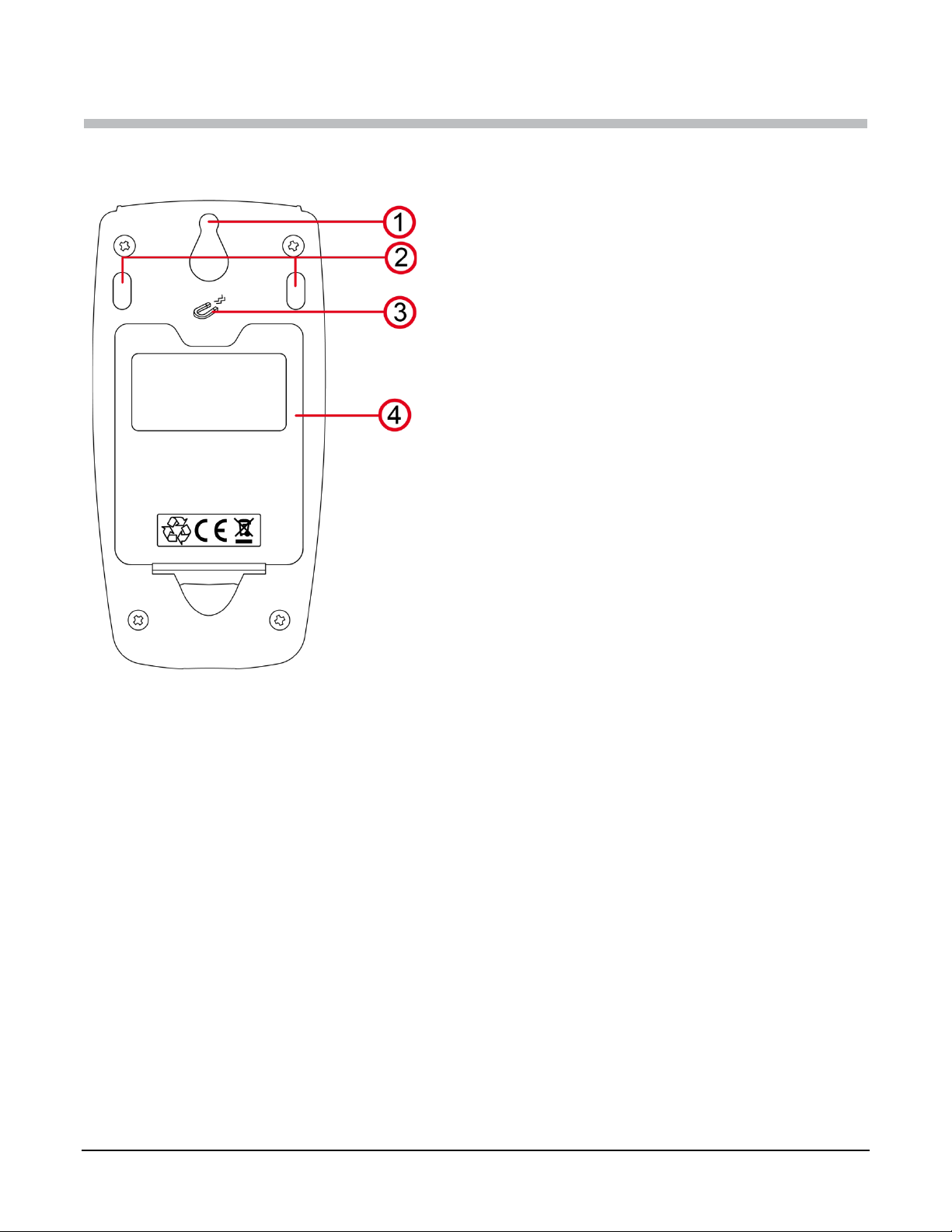
1.1. Battery Installation
The instrument accepts three AA or LR6 alkaline batteries.
1. “Tear-drop” notch to hang instrument
2. Non-skid pads
3. Magnets for mounting to a metallic surface
4. Battery compartment cover
To change the batteries:
1. Press the tab of the battery compartment cover and lift it clear.
2. Remove the battery compartment cover.
3. Insert the new batteries, ensuring correct polarity.
4. Close the battery compartment cover; ensuring it is completely and correctly closed.
Thermo-Anemometer Data Logger Model 1227 3
Page 7
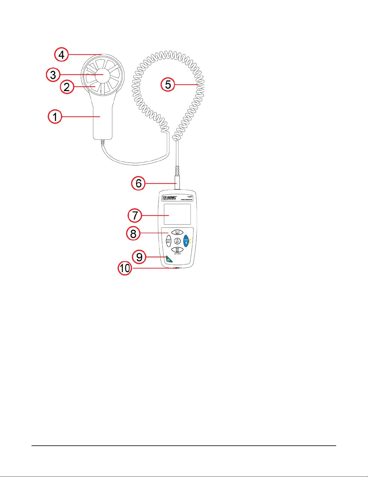
1.2. Instrument Components
1. Sensor handle
2. Propeller
3. Temperature sensor
4. Flow direction arrow
5. Spiral-wound connector cable
6. Four-conductor 3.5mm jack
7. Backlit LCD display
8. Keypad
9. ON/OFF button
10.Type B micro-USB connector
1.3. Instrument Functions
The Model 1227 measures air speed from 0.25 to 35m/s, as well as volume flow from 0 to 99.999m3/h. It also
measures temperature from 14 to 140°F (-10 to 60°C).
This instrument is easy to use. It has extensive stand-alone capabilities and can:
Display temperature measurements in °C or °F
Display air speeds in m/s and km/h or in fpm and mph
Display volume flows in m3/s, m3/h, l/s, or CFM
Record minimum, average, and maximum measurements in a specified period
Record minimum, average, and maximum measurements for a location
Record measurements and store them in memory
Communicate with a computer via Bluetooth® or USB cable
DataView with the Data Logger Control Panel software can be installed on a computer to allow you to configure
the instrument, view measurements in real time, download data from the instrument, and create reports.
4 Thermo-Anemometer Data Logger Model 1227
Page 8
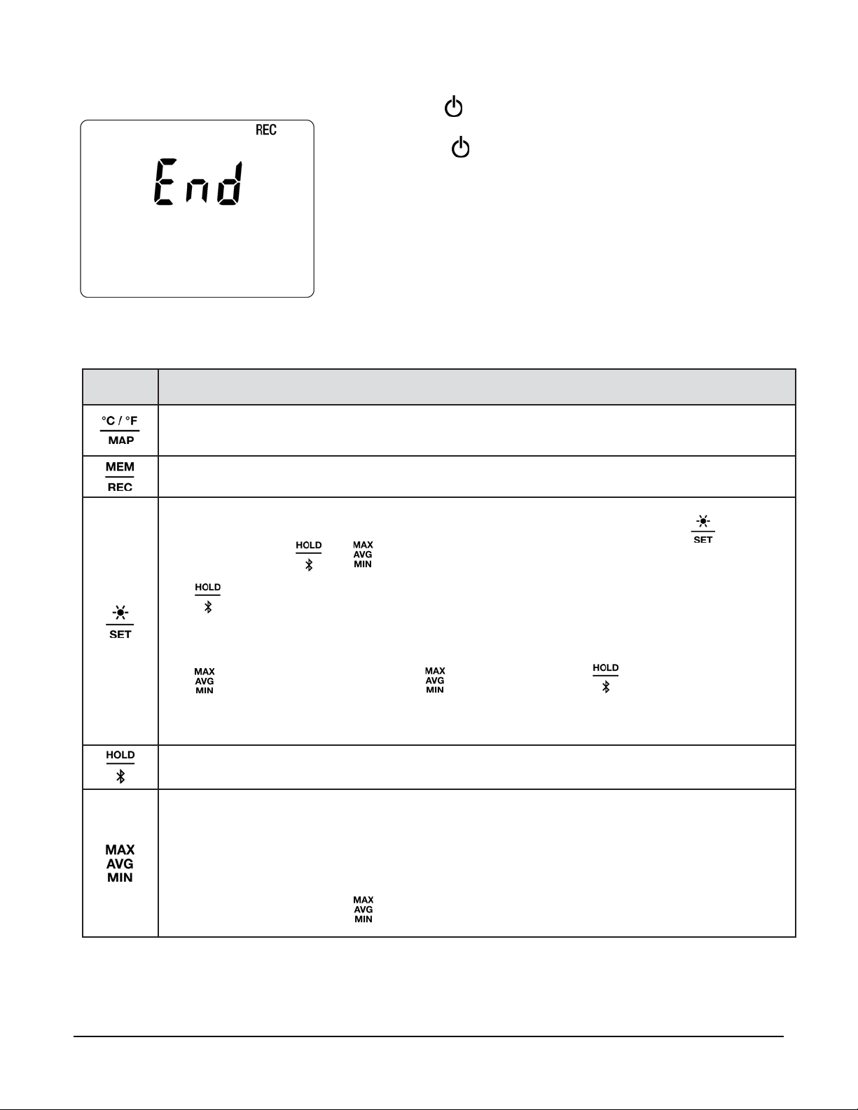
1.4. Turning the Instrument ON/OFF
ON: Press the button for >2 seconds.
OFF: Press the button for >2 seconds when the instrument is ON.
Note that you cannot turn OFF the instrument when it is in recording
or HOLD mode.
If the screen on the left appears during start-up, a recording session was
still in progress the last time the instrument lost power. This screen
indicates the instrument is saving the recorded data.
Do not turn OFF the instrument while this screen is displayed; otherwise
the recorded data will be lost.
1.5. Function Buttons
Key Function
Short press toggles between °C and °F.
Long press (>2 seconds) enables MAP mode.
Short press records the measurement and date.
Long press starts/stops a recording session.
Short press turns on the backlight.
Press and hold down this button to select measurement parameters. When the button is
held down, the and buttons perform the following functions:
cycles through the measurement value options. These include FLOW IN (volume of air
flowing into a cone), FLOW OUT (volume of air flowing out of a cone), FLOW CUST (volume of
air measured without a cone), and VELOC (air speed).
sets the unit of measure for the value selected via the button. These include:
(air flow values) M
(VELOC) F/M, KM/H, M/H)
Short press freezes the display.
Long press activates/deactivates Bluetooth.
Short press enters MAX AVG MIN mode; the current values continue to be displayed.
Second press displays the maximum value measured in MAX AVG MIN mode.
Third press displays the average value.
Fourth press displays minimum value.
Fifth press returns to current values.
Long press exits MAX AVG MIN mode.
In MAP mode, pressing cycles through the maximum, average (mean), and minimum of
the MAP measurements.
3
/S, M3/H, L/S, CF/M
Thermo-Anemometer Data Logger Model 1227 5
Page 9

1.6. Display
2
1
1. Air speed and flow display measurement
2. Temperature measurement/MAP
function counter
OL indicates the measurement is outside the instrument limits (positive or negative).
indicates Auto OFF is disabled. This occurs when the instrument is:
Recording, in MAX AVG MIN mode, in MAP mode, or in HOLD mode
Connected via the USB cable either to an external power supply or for communication with a computer
Communicating via Bluetooth
Set to Auto OFF disabled (see §2.4).
6 Thermo-Anemometer Data Logger Model 1227
Page 10

2. SETUP
Before using your instrument, you must set its date and time via DataView. Other basic setup tasks include
selecting:
Bluetooth enabled (can be done on the instrument or via DataView)
°F or °C for measurement units (can be done on the instrument or via DataView)
Auto OFF interval (requires DataView)
2.1. DataView Installation
1. Insert the USB drive that comes with the instrument into a USB port on your computer.
2. If Autorun is enabled, an AutoPlay window appears on your screen. Click “Open folder to view files” t
splay the DataView folder. If Autorun is not enabled or allowed, use Windows Explorer to locate and
di
open the USB drive labeled “DataView.”
3. When the DataView folder is open, find the file Setup.exe and double-click it.
4. The Setup screen appears. This enables you to select the language version of DataView to install. You
can also select additional install options (each option is explained in the Description field). Make your
selections and click Install.
5. The InstallShield Wizard screen appears. This program leads you through the DataView install process.
As you complete these screens, be sure to check Data Loggers when prompted to select features t
install.
6. When the InstallShield Wizard finishes installing DataView, the Setup screen appears. Click Exit t
lose. The DataView folder appears on your computer desktop.
c
o
o
o
2.2. Connecting the Instrument to a Computer
You can connect the instrument to a computer either through the supplied USB cable or Bluetooth®. The first two
steps of the connection procedure depend on the connection type:
U
SB:
1. Connect the instrument to an available USB port using the supplied cable.
2. Turn ON the instrument. If this is the first time this instrument has been connected to this computer, the
dr
ivers will be installed. Wait for driver installation to finish before proceeding with step 3 below.
Bluetooth:
Connecting the instrument via Bluetooth requires a Bluegiga BLED112 Smart Dongle (sold separately) installed in
your computer. When the dongle is installed, do the following:
1. Turn ON the instrument by pressing the button.
2. Activate Bluetooth on the instrument by pressing th
fter the USB cable is connected or Bluetooth is activated, proceed as follows:
A
3. Open the DataView folder on your desktop. This displays a list of icons for the Control Panel(s) install
with DataVie w.
4. Open the DataView Data Logger Control Panel by clicking the icon.
5. In the menu bar at the top of the screen, select Help. In the drop-down menu that appears, click t
ion Help Topics. This opens the Data Logger Control Panel Help system.
opt
6. Use the Contents window in the Help system to locate and open the topic "Connecting to an Instrument."
This provides instructions explaining how to connect your instrument to the computer.
7. When the instrument is connected, its name appears in the Data Logger Network in the left side of t
ontrol Panel. A green check mark appears next to the instrument name indicating it is currently
C
connected.
e but
ton until the symbol appears in the LCD.
ed
he
he
Thermo-Anemometer Data Logger Model 1227 7
Page 11

2.3. Instrument Date/Time
1. Select the instrument in the Data Logger Network.
2. In the menu bar, select Instrument. In the drop-down menu that appears, click Set Clock.
3. The Date/Time dialog box appears. Complete the field in this dialog box. If you need assistance, press
F1.
4. When you are finished setting the date and time, click OK to save your changes to the instrument.
2.4. Auto OFF
By default, the instrument automatically turns OFF after 3 minutes of inactivity. You can use the Data Logger
Control Panel to change the Auto OFF interval, or disable this feature, as instructed by the Help that comes with
the software.
When Auto OFF is disabled, the symbol appears in the instrument LCD screen.
2.5. Temperature Units
The button on the instrument front panel allows you to toggle between °C and °F as the temperature
measurement unit.
8 Thermo-Anemometer Data Logger Model 1227
Page 12

3. STANDALONE OPERATION
The instrument can operate in two modes:
Stand-alone mode, described in this section
Remote mode, in which the instrument is controlled by a computer running DataView (see §4)
3.1. Making Measurements
3.1.1. Air Speed
1. Connect the sensor to the instrument.
2. If the instrument is OFF, press and hold down the button until it turns ON.
3. Press and hold down the button. While holding this button down, shortpress the button to cycle through the measurement options until VELOC
appears on the LCD.
4. While continuing to hold down , short-press to select the air speed
units of measure. Options are M/S (meters per second), F/M (feet per
minute), KM/H (kilometers per hour), and M/H (miles per hour). When the
desired measurement is displayed, release .
5. To change temperature units, short-press .
6. Hold the sensor in the air flow. The arrow on the inside of the propeller must point in the direction of the
flow (see illustration to the left). This ensures the temperature sensor faces the incoming air, allowing it to
display an accurate value m or e quick l y.
7. The air speed and temperature measurements are displayed on the LCD. (Wait for the measurements to
stabilize before accepting the reading.)
Always hold the sensor by its handle. Keep your fingers away from the sensor propeller.
Note that if you turn the instrument OFF, the configuration settings selected in steps 1 through 6 above will still be
in effect the next time you turn the instrument ON.
3.1.2. Air Flow (Volume)
The Model 1227 can measure air flow both with and without using an optional air flow cone. Cones are typically
used for measuring air flow through grated ventilation registers and other passages where the flow is disrupted
and distorted, resulting in inconsistent measurements. The cone can help "normalize" the air flow by directing
most or all the air towards the instrument's sensor, providing a more consistent measurement. Two models of
cones are available as accessories, one wit h a rou nd 7.9” ( 20cm) opening, and the other with a square 13”
(33cm) opening.
Thermo-Anemometer Data Logger Model 1227 9
Page 13

Before you begin, ensure the instrument is turned ON and connected to the sensor. Then do the following:
1. Sensor
4. Cone
2. Cone handle
5. Ventilation register
3. Air flow direction (in this example,
air flow is incoming)
5
1. Press and hold down the button. While holding this button down, short-press the button to cycle
through the measurement options until the desired FLOW setting appears on the LCD. Choices are:
In - measures incoming (blowing) air flow with a cone.
out - measures outgoing (suction) air flow with a cone.
CUSt - measures air flow without a cone. If you select this option, you must enter the area of the
ventilation register into the DataView Data Logger Control Panel, as explained in step 4 below. The
instrument can then calculate air flow using the speed measurement and ventilation area setting.
2. While continuing to hold down , short-press to select the air flow units of measure. Options are
M3/S (cubic meters per second), M3/H (cubic meters per hour), L/S (liters per second), and CF/M (cubic
feet per minute). When the desired measurement is displayed, release .
3. To change temperature units, short-press .
4. If you are using an air flow cone: Skip the remainder of this step and proceed with step 5 below.
If you are not using a cone: Connect the instrument to a computer using DataView (§2.2). Select the
instrument in the Data Logger Network and click Instrument -> Configure. Then go to the Anemometer
tab, select Custom, and enter the area of the ventilation register. (Consult the DataView Data Logger
Help system for assistance.) When finished, place the sensor in front of the ventilation register, and go to
step 7 below.
5. Place the air flow measurement cone on the sensor. Depending on the measurement you want to make
(flow in or flow out), place the sensor with the arrow pointing towards the cone (outgoing flow) or away
from it (incoming flow).
6. Place the cone on the ventilation register. The arrow inside the propeller must point in the direction of
the air flow. This will be towards the outside of the cone for a blowing measurement, or towards the inside
of the cone for a suction measurement.
7. The air flow and temperature measurements are displayed on the LCD. (Wait for the measurements to
stabilize before accepting the reading.)
Always hold the sensor by its handle. Keep your fingers away from the sensor propeller.
10 Thermo-Anemometer Data Logger Model 1227
Page 14

3.1.3. HOLD Function
Pressing the button freezes the display. A second press unfreezes it.
3.1.4. MAX AVG MIN Function
You can monitor the maximum, minimum, and average measurements by pressing the button. This displays the
words MIN/AVG/MAX at the top of the display (see the following illustration). In this mode, pressing once
displays the maximum value measured during the current session. A second press displays the average value,
and a third displays the minimum. Finally a fourth press restores the normal display. Subsequent presses of
repeat this cycle.
To exit MAX AVG MIN mode, long-press . Note that when MAX AVG MIN mode is active, the MAP function is
deactivated.
3.1.5. MAP Function
The MAP function enables you to map air speed, air flow, or temperature for a 2-dimensional space or surface.
For example, in MAP mode you can measure the air speed at specific points within a room. You can then
download the recording to a computer running DataView, and display the measurements as a 2-dimensional
matrix, creating a “map” of the air speed within the room.
Before mapping an area, it is good practice to create a chart identifying where to make measurements. For
instance, the following illustration is an example measurement chart for a room. Each red circle r epr esent s a
measurement point.
To enter MAP mode, press for >2 seconds. Place the sensor at the first measurement point and press to
record the value in memory. The MAP counter is incremented. Repeat this step for all the other points of the map.
Thermo-Anemometer Data Logger Model 1227 11
Page 15

Er.01
Er.03
Er.11
Er.13
When all points have been measured, you can display the maximum, average, and minimum values. To do this,
press three times to cycle through the maximum, average, and minimum values respectively.
To exit MAP mode, long-press .
For each map, a file is created containing all measurement points. This file can then be downloaded and
analyzed.
3.2. Recording Measurements
You can start and stop a recording session on the instrument. Recorded data is stored in the instrument’s
memory, and can be downloaded and viewed on a computer running the DataView Data Logger Control Panel.
You can record data by pressing the button:
A short press (MEM) records the current measurement(s) and date.
A long press (REC) starts the recording session. While the recording is in progress, the symbol REC
appears at the top of the display. A second long press of stops the recording session. Note that while
the instrument is recording, a short press of has no effect.
To schedule recording sessions, and download and view recorded data, see §4.
3.3. Errors
The instrument detects errors and displays them in the form Er.XX:
Hardware malfunction detected. The instrument must be sent in for repair.
Er.02
Er.10
Er.12
Error in internal memory. Format the memory.
Hardware malfunction detected. The instrument must be sent in for repair.
The instrument has not been correctly adjusted. The instrument must be sent in for calibration.
The firmware is incompatible with the instrument. Install the correct firmware (see §6.3).
The firmware version is incompatible with the instrument. Reload the previous firmware version.
Recording scheduling error. Ensure that the instrument’s time and the time of the DataView Data
Logger Control Panel are the same (see §2.3).
12 Thermo-Anemometer Data Logger Model 1227
Page 16

4. DATAVIEW
As explained in §2, DataView is required to perform several basic setup tasks including connecting the instrument
to a computer, setting the time and date on the instrument, and changing the Auto OFF setting. In addition,
DataView allows you to:
Configure and schedule a recording session on the instrument.
Download recorded data from the instrument to the computer.
Generate reports from downloaded data.
View instrument measurements in real time on the computer.
For information about performing these tasks, consult the DataView Data Logger Control Panel Help.
Thermo-Anemometer Data Logger Model 1227 13
Page 17

5. TECHNICAL CHARACTERISTICS
Quantity of influence
Reference values
Temperature
73 ± 3.6°F (23 ± 2°C)
Relative humidity
45% to 75%
Supply voltage
3 to 4.5V
Electric field
< 1V/m
Magnetic field
< 40A/m
Specified measurement range
-4 to +122°F
-20 to +50°C
Resolution
0.1°F
0.1°C
Intrinsic uncertainty
From 32 to 122°F: ± 1.4°F
From -4 to 32°F: ± 2.9°F
from 0 to 50°C: ± 0.8°C
from -20 to 0°C: ± 1.6°C
m/s
km/h
Specified measurement range
0.25 to 2.99 m/s
3.0 to 35.0
m/s
0.90 to 2.99
km/h
3.0 to 99.9
km/h
100 to 126
km/h
Resolution
0.01 m/s
0.1 m/s
0.01 km/h
0.1 km/h
1 km/h
Intrinsic uncertainty
± 3% R ± 4 cts
± 3% R ± 4
fpm
mph
Specified measurement range
49.0 to 99.9 fpm
100 to 6,890 fpm
0.56 to 2.99 mph
3.0 to 78.3 mph
Resolution
0.1 fpm
1 fpm
0.01 mph
0.1 mph
m3/s
Resolution
0.0001 m3/s
0.001 m3/s
0.01 m3/s
0.1 m3/s
1 m3/s
Intrinsic uncertainty
± 8% R
m3/h
R/s
range
0.01 m3/h
0.1 m3/h
1 m3/h
Intrinsic uncertainty
± 8% R
± 8% R
Resolution
0.01 cfm
0.1 cfm
1 cfm
Intrinsic uncertainty
± 8% R
5.1. Reference Conditions
The intrinsic uncertainty is the error specified for the reference conditions. It is expressed in the form: % R + b ct,
where R = reading (for example ± 3% R ± 4 cts).
5.2. Electrical Specifications
5.2.1. Temperature Measu rem ent s
5.2.2. Air Speed Measurements
5.2.3. Air Flow Measurements
Specified measurement
range
Specified measurement
Resolution
Specified measurement range
14 Thermo-Anemometer Data Logger Model 1227
0.0000 to
0.9999 m3/s
0.00 to 2.99 m3/h 3.0 to 99.9 m3/h 100 to 2999 m3/h
0.00 to 2.99 cfm 3.0 to 99.9 cfm 100 to 2999 cfm
0.100 to 0.999
m3/s
1.00 to 2.99
m3/s
3.0 to 99.9
m3/s
100 to 99999
m3/s
0.00 to 2.99 R/s
0.01 R/s
Page 18

5.3. Memory
Parameter Value
Memory 8MB Flash (non-volatile)
Storage rate Standalone recordings: 1 s
Recordings configured via Dat a View : 1 s, 2 s, 5 s, 10 s, 20 s, 30 s, 1 min,
2 min, 5 min, 10 min, 15 min, 30 min, 1 hour (selectable via Data Logger
Control Panel)
Maximum recording length Dependent on storage rate. For example:
1 s storage rate = 21 days maximum recording
1 hour storage rate = multiple years maximum recording
5.4. USB
Protocol: USB Mass Storage
Maximum transmission speed: 12Mbit/s
Type B micro-USB connector
5.5. Bluetooth
Bluetooth 4.0 BLE
Range 33’ (10m) typical and up to 100’ (30m) in line of sight.
Output power: +0 to -23dBm
Nominal sensitivity: -93dBm
Maximum transfer rate: 10 kbits/s
Average consumption: 3.3µA at 3.3V.
5.6. Power Supply
The instrument is powered by three 1.5V LR6 or AA alkaline batteries. You can replace the batteries with
rechargeable NiMH batteries of the same size. But the rechargeable batteries, even when correctly charged, will
not reach the voltage of the alkaline batteries and the battery life indicated will be or .
The voltage range for correct operation is 3 to 4.5V for alkaline batteries and 3.6V for the rechargeable batteries.
Below 3V, the instrument stops taking measurements and displays BAt. Battery life (with the Bluetooth connection
deactivated) is:
standby mode: 200 hours
recording mode: 8 days at a rate of one measurement every 15 minutes
The instrument can also be powered via a USB-micro USB cable, connected either to a computer or to a wall
outlet via an adapter.
> 110 VAC
< 240 VAC
50 / 60 Hz
2.5 W
5.7. Environmental Conditions
For use indoors and outdoors.
Operating range: 14 to 140°F (-10 to 60°C) and 10 to 90%RH without condensation
Storage range: -4 to 158°F (-20 to 70°C) and 10 to 95%RH without condensation, without batteries
Altitude: < 6562’ (< 2000m), and 32,800’ (10,000m) in storage.
Pollution degree: 2
Thermo-Anemometer Data Logger Model 1227 15
Page 19

5.8. Mechanical Characteristics
Dimensions (L x W x H):
Housing: 5.9 x 2.8 x 1.26” (150 x 72 x 32mm)
Sensor: 6.3 x 3.15 x 1.5” (160 x 80 x
Spiral-wound cable: 9.45 x 47.2” (24 to 120cm)
Mass: approximately 14.1oz (400g)
Inrush protection: IP 50, with the USB connector closed, per IEC 60 529.
Drop impact tes
t: 3.28’ (1m) per IEC 61010-1.
38mm)
5.9. Compliance with International Standards
The instrument is compliant with standard IEC 61010-1.
5.10. Electromagnetic Compatibility (CEM)
The instrument is compliant with standard IEC 61326-1.
16 Thermo-Anemometer Data Logger Model 1227
Page 20

6. MAINTENANCE
Except for the batteries, the instrument contains no parts that can be replaced by personnel
who have not been specially trained and accredited. Any unauthorized repair or replacement of
a part by an “equivalent” may gravely impair safety.
6.1. Cleaning
To preserve good measurement quality, the sensor propeller must be kept clean.
1. Switch the instrument OFF.
2. Clean instrument with a soft cloth, dampened with soapy water.
3. Rinse with a damp cloth and dry rapidly with a dry cloth or forced air. Do not use alcohol, solvents, or
hydrocarbons.
Ensure that nothing interferes with the rotation of the propeller.
6.2. Battery Replacement
The symbol indicates the remaining battery life. When the symbol is empty, all of the batteries must be
replaced. To do this, turn the instrument OFF and refer to §1.1 for the installation procedure.
Spent batteries must not be treated as ordinary household waste. Take them to an appropriate recycling
collection facility.
6.3. Firmware Update
AEMC may periodically update the instrument’s firmware. Updates are available for free download. To check for
updates:
1. Connect the instrument to the Data Logger Control Panel.
2. Click Help.
3. Click Update. If the instrument is running the latest firmware, a message appears informing you of this. If
an update is available, the AEMC Download page automatically opens. Follow the instructions listed on
this page to download the update.
After firmware updates, it may be necessary to reconfigure the instrument (see §2).
Thermo-Anemometer Data Logger Model 1227 17
Page 21

REPAIR AND CALIBRATION
To ensure that your instrument meets factory specifications, we recommend that it be scheduled to be sent back
to our factory Service Center at one-year intervals for recalibration, or as required by other standards or internal
procedures.
For instrument repair and calibration:
You must contact our Service Center for a Customer Service Authorization Number (CSA#). This will ensure that
when your instrument arrives, it will be tracked and processed promptly. Please write the CSA# on the outside of
the shipping container. If the instrument is returned for calibration, we need to know if you want a standard
calibration or a calibration traceable to N.I.S.T. (Includes calibration certificate plus recorded calibration data).
For North / Central / South America, Australia and New Zealand:
Ship To: Chauvin Arnoux®, Inc. d.b.a. AEMC® Instruments
15 Faraday Drive • Dover, NH 03820 USA
Phone: (800) 945-2362 (Ext. 360)
(603) 749-6434 (Ext. 360)
Fax: (603) 742-2346 • (603) 749-6309
E-mail: repair@aemc.com
(Or contact your authorized distributor.)
Costs for repair, standard calibration, and calibration traceable to N.I.S.T. are available.
NOTE: You must obtain a CSA# before returning any instrument.
TECHNICAL AND SALES ASSISTANCE
If you are experiencing any technical problems, or require any assistance with the proper operation or application
of your instrument, please call, fax, or e-mail our technical support team:
®
Contact: Chauvin Arnoux
Phone: (800) 945-2362 (Ext. 351) • (603) 749-6434 (Ext. 351)
Fax: (603) 742-2346
E-mail: techsupport@aemc.com
, Inc. d.b.a. AEMC® Instruments
18 Thermo-Anemometer Data Logger Model 1227
Page 22

LIMITED WARRANTY
Your AEMC instrument is warranted to the owner for a period of two years from the date of original purchase
against defects in manufacture. This limited warranty is given by AEMC
whom it was purchased. This warranty is void if the unit has been tampered with, abused, or if the defect is
related to service not performed by AEMC
Full warranty coverage and product registration is available on our website at:
www.aemc.com/warranty.html.
Please print the online Warranty Coverage Information for your records.
®
Instruments.
®
Instruments, not by the distributor from
What AEMC® Instruments will do:
If a malfunction occurs within the two-year period, you may return the instrument to us for repair, provided we
have your warranty registration information on file or a proof of purchase. AEMC
repair or replace the faulty material.
®
Instruments will, at its option,
Warranty Repairs
What you must do to return an Instrument for Warranty Repair:
First, request a Customer Service Authorization Number (CSA#) by phone or by fax from our Service Department
(see address below), then return the instrument along with the signed CSA Form. Please write the CSA# on the
outside of the shipping container. Return the instrument, postage or shipment pre-paid to:
®
Ship To: Chauvin Arnoux
15 Faraday Drive • Dover, NH 03820 USA
Phone: (800) 945-2362 (Ext. 360)
(603) 749-6434 (Ext. 360)
Fax: (603) 742-2346 • (603) 749-6309
E-mail: repair@aemc.com
, Inc. d.b.a. AEMC® Instruments
Caution: To protect yourself against in-transit loss, we recommend you insure your returned material.
NOTE: You must obtain a CSA# before returning any instrument.
Thermo-Anemometer Data Logger Model 1227 19
Page 23

NOTES:
20 Thermo-Anemometer Data Logger Model 1227
Page 24

01/18
99-MAN 100449 v1
Chauvin Arnoux®, Inc. d.b.a. AEMC® Instruments
15 Faraday Drive • Dover, NH 03820 USA • Phone: (603) 749-6434 • Fax: (603) 742-2346
www.aemc.com
 Loading...