

Page 1
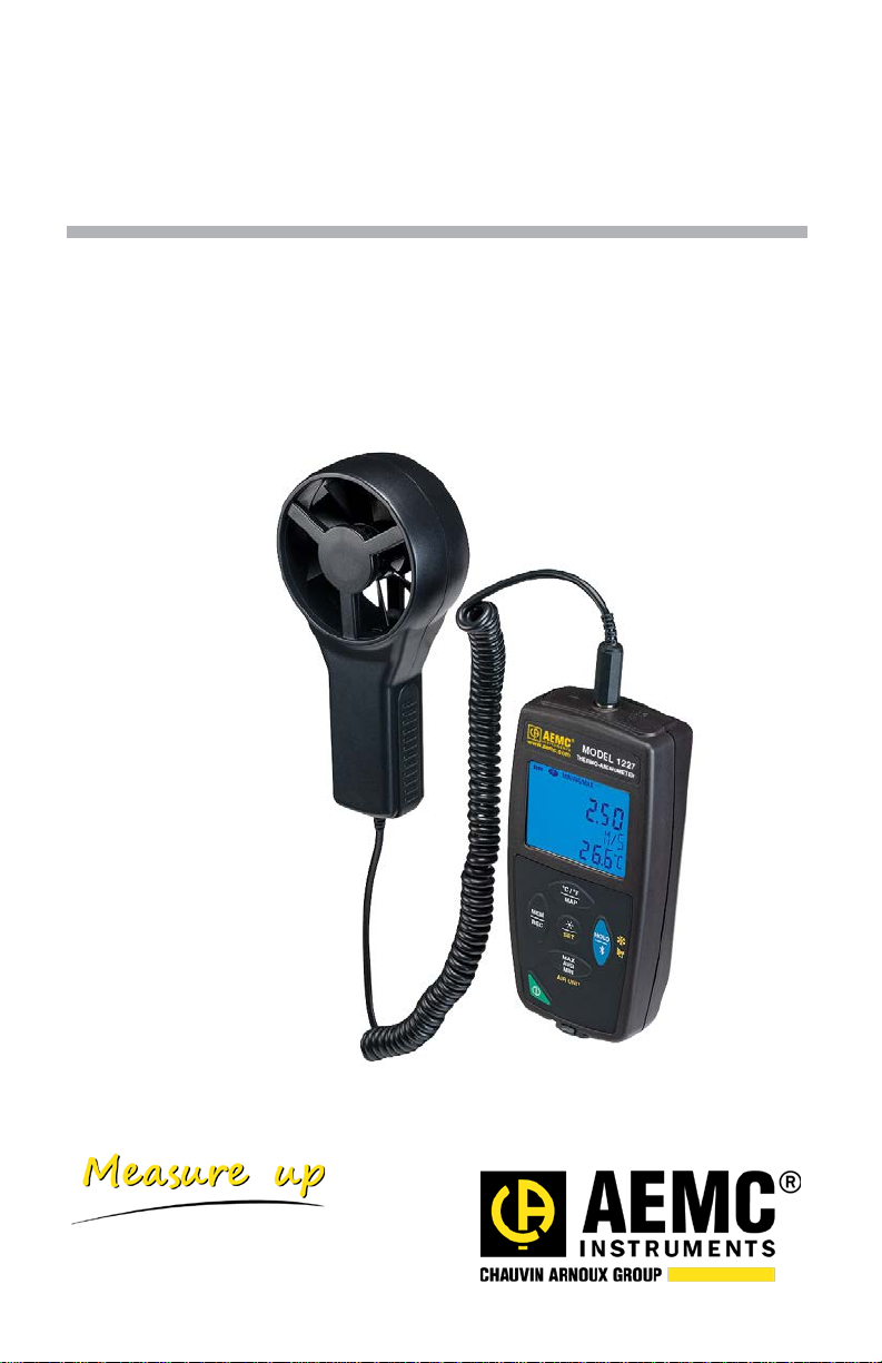
Thermo-Anemometer
Data Logger Model 1227
Quick Start Guide
ENGLISH
www.aemc.com
Page 2

Statement of Compliance
Chauvin Arnoux®, Inc. d.b.a. AEMC® Instruments certifies
that this instrument has been calibrated using standards
and instruments traceable to international standards.
We guarantee that at the time of shipping your instrument
has met its published specifications.
An N.I.S.T. traceable certificate may be requested at the
time of purchase, or obtained by returning the
instrument to our repair and calibration facility, for a
nominal charge.
The recommended calibration interval for this instrument
is 12 months and begins on the date of receipt by the
customer. For recalibration, please use our calibration
services. Refer to our repair and calibration section at
www.aemc.com
Serial #:
Catalog #: 2121.72
.
Model #: 1227
Please fill in the appropriate date as indicated:
Date Received:
Date Calibration Due:
Chauvin Arnoux®, Inc.
d.b.a AEMC
w
ww.aemc.com
®
Instruments
1
Page 3
Thank you for purchasing the Thermo-Anemometer Data Logger Model 1227. For best
The Model 1227 is designed to operate with system voltages less than
results from your instrument:
read these operating instructions carefully
comply with the precautions for use
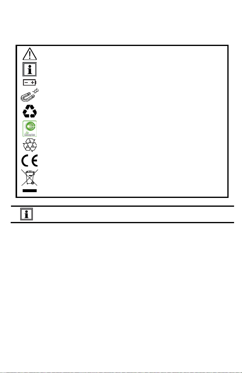
WARNING, risk of DANGER! The operator must refer to these
instructions whenever this danger symbol appears.
Information or useful tip.
Battery.
Magnet.
The product has been declared recyclable after analysis of its life cycle
in accordance with the ISO14040 standard.
AEMC has adopted an Eco-Design approach in order to design this
appliance. Analysis of the complete lifecycle has enabled us to control
and optimize the effects of the product on the environment. In particular
this appliance exceeds regulation requirements with respect to recycling
and reuse.
Indicates conformity with European directives and with regulations
covering EMC.
Indicates that, in the European Union, the instrument must undergo
selective disposal in compliance w ith Dire ctive WEEE 2002/96/EC. This
instrument must not be treated as household waste.
75VDC.
Precautions
This instrument is compliant with safety standard IEC 61010-2-030, for voltages up to 5V
with respect to ground. Failure to observe the following safety instructions may result in
electric shock, fire, explosion, and damage to the instrument and/or the installation in
which it is located.
The operator and/or the responsible authority must carefully read and clearly
understand all precautions to be taken prior to using the instrument. Thorough
knowledge and awareness of electrical hazards are essential when using this
instrument.
Observe all conditions of use, including temperature, relative humidity, altitude,
pollution degree, and location of use.
Do not use instrument if it appears damaged, incomplete, or improperly closed.
Before each use, check condition of hous ing and accessories. Any item on which
the insulation is deteriorated must be set aside for repair or disposal.
Always hold the sensor handle, and keep your fingers away from the propeller.
Troubleshooting and metrological checks must be done by accredited personnel.
2
Page 4

INITIAL SETUP
Installing Batteries
1. Press the tab of the battery compartment cover and lift it clear.
2. Remove the battery compartment cover.
3. Insert the new batteries, ensuring correct polarity.
4. Close the battery compartment cover; ensuring it is completely and correctly
closed.
Connecting to a Computer
The Model 1227 must be connected to DataView
detailed setup instructions, see the User Manual in the USB drive that comes with the
instrument.) To connect the Model 1227 to your computer:
1. Install the DataView
Panel as an option (it is selected by default). De-select any Control Panels you
do not need.
2. If prompted, restart the computer after installation is complete.
3. Connect the instrument to the computer using a USB cable or pair with
Bluetooth.
4. Wait for the drivers to install. The drivers are installed the first time the
instrument is connected to the computer. The Windows operating system will
display messages indicating when the installation is complete.
5. Start the Data Logger Control Panel by double-clicking the Data Logger
shortcut icon in the DataView folder placed on the desktop during the
installation.
6. Click Instrument in the menu bar, and select Add an Instrument.
7. The Add an Instrument Wizard dialog box opens. This is the first of a series of
screens that lead you through the instrument connection process. The first
screen prompts you to select the connection type (USB or Bluetooth). Choose
the connection type and click Next.
8. If the instrument is identified, click Finish. The instrument is now
communicating with the Control Panel.
9. When you are finished, the instrument will appear in the Data Logger Network
branch in the Navigation frame, with a green check mark indicating a successful
connection.
®
software, making sure to select the Data Logger Control
®
before it can be configured. (For
Setting the Instrument’s Clock
To ensure an accurate time stamp of measurements recorded in the instrument, set the
instrument’s clock as follows:
1. Select the instrument in the Data Logger Network.
2. In the menu bar, select Instrument. In the drop-down menu that appears, click
Set Clock.
3. The Date/Time dialog box appears. Complete the fields in this dialog box. If you
need assistance, press F1.
4. When you are finished setting the date and time, click OK to save your changes
to the instrument.
3
Page 5
INSTRUMENT CONFIGURATION
In addition to setting the instrument’s clock, other basic setup tasks include:
Enabling Bluetooth (can be don e on the instrument or via DataView)
Setting measurement units to °F or °C (can be done on the instrument or via
DataView)
Changing the Auto OFF interval (requires DataView)
Detailed information for configuring the instrument via the DataView Data Logger Control
Panel is available by pressing the Help button.
Enabling Bluetooth
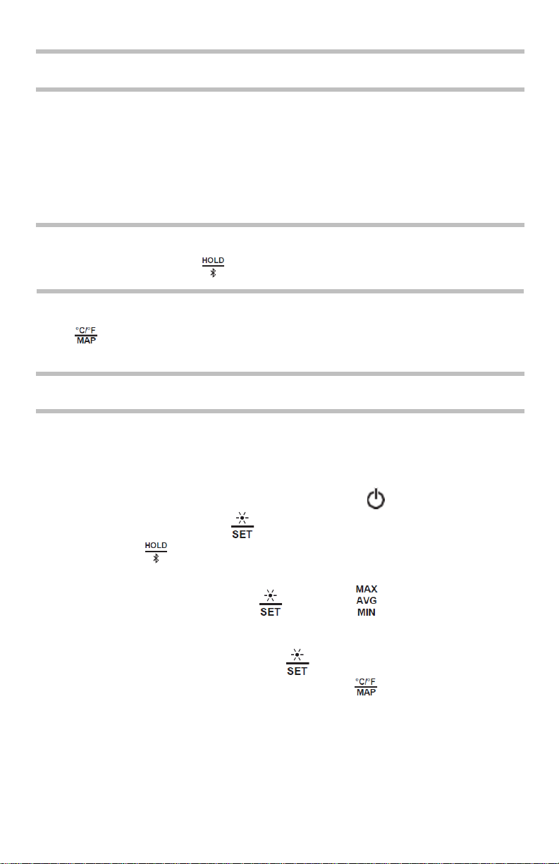
Long press (>2 seconds) the button to enable/disable Bluetooth.
Selecting Temperature Units
Press to toggle between °C and °F.
OPERATION
Making Measurements
Air Speed:
1. Connect the sensor to the instrument.
2. If the instrument is OFF, press and hold down the button until it turns ON.
3. Press and hold down the button. While holding this button down, shortpress the button to cycle through the measurement options until VELOC
appears on the LCD.
4. While continuing to hold down , short-press to select the air speed
units of measure. Options are M/S (meters per second), F/M (feet per minute),
KM/H (kilometers per hour), and M/H (miles per hour). When the desired
measurement is displayed, release .
5. To change temperature units, short-press .
6. Hold the sensor in the air flow. The arrow on the inside of the propeller must
point in the direction of the flow. This ensures the temperature sensor faces the
incoming air, allowing it to display an accurate value more quickly.
7. The air speed and temperature measurements are displayed on the LCD. (Wait
for the measurements to stabilize before accepting the reading.)
4
Page 6

Air Flow:
1. Press and hold down the button. While holding this button down, short-press
the button to cycle through the measurement options until the desired FLOW
setting appears on the LCD. Choices are:
In - measures incoming (blowing) air flow with a cone.
out - measures outgoing (suction) air flow with a cone.
CUSt - measures air flow without a cone. If you select this option, you must enter
the area of the ventilation regist er into the DataView Data Logger Control Panel,
as explained in step 4 below. The instrument can then calculate air flow using the
speed measurement and ventilation area setting.
2. While continuing to hold down , short-press to select the air flow units of
measure. Options are M3/S (cubic meters per second), M3/H (cubic meters per
hour), L/S (liters per second), and CF/M (cubic feet per minute). When the desired
measurement is displayed, release .
3. To change temperature units, short-press .
4. If you are using an air flow cone: Skip the remainder of this step and proceed
with step 5 below.
If you are not using a cone: Connect the instrument to a computer using
DataView. Select the instrument in the Data Logger Network and click Instrument
-> Configure. Then go to the Anemometer tab, select Custom, and enter the
area of the ventilation register. (Consult the DataView Data Logger Help system
for assistance.) When finished, place the sensor in fron t of the ventilation register,
and go to step 7 below.
5. Place the air flow measurement cone on the sensor. Depending on the
measurement you want to make (flow in or flow out), place the sensor with the
arrow pointing towards the cone (outgoing flow) or away from it (incoming flow).
6. Place the cone on the ventilation register. The arrow inside the propeller must
point in the direction of the air flow. This will be towards the o utside of the cone
for a blowing measurement, or towards the inside of the cone for a suction
measurement.
7. The air flow and temperature measurements are displayed on the LCD. (Wait for
the measurements to stabilize before accepting the reading.).
Recording Measurements
You can start and stop a recording session on the instrument. Recorded data is stored in
the instrument’s memory, and can be downloaded and viewed on a computer running the
DataView Data Logger Control Panel. You can record data by pressing the button:
5
Page 7

A short press (MEM) records the current measurement(s) and date.
A long press (REC) starts the recording session. While the recording is in
progress, the symbol REC appears at the top of the display. A second long press
of stops the recording session. Note that while the instrument is recording, a
short pres s of has no effect.
To schedule recording sessions , and download and view recorded data, see the
Data Logger Control Panel Help.
Repair and Calibration
To ensure that your instrument meets factory specifications, we recommend that it be
sent back to our factory Service Center at one-year intervals for recalibration, or as
required by other standards or internal procedures.
For instrument repair and calibration:
You must contact our Service Center for a Customer Service Authorization Number
(CSA#). This will ensure that when your instrument arrives, it will be tracked and
processed promptly. Please write the CSA# on the outside of the shipping container. If
the instrument is returned for calibration, we need to know if you want a standard
calibration; or a calibration traceable to N.I.S.T. (includes calibration certificate plus
recorded calibration data).
Ship To: Chauvin Ar n oux
15 Faraday Drive
Dover, NH 03820 USA
Phone: (800) 945-2362 (Ext. 360)
(603) 749-6434 (Ext. 360)
Fax: (603) 74 2-2346 or (603) 749-6309
E-mail: repair@aemc.com
(Or contact your authorized distributor.)
Cost for repair, standard calibration, and calibration traceable to N.I.S.T. are available.
NOTE: You must obta in a CSA# before returning any instrument.
®
, Inc. d.b.a. AEMC® Instruments
Technical and Sales Assistance
If you are experiencing any technical problems, or require any assistance with the
proper operation or application of your instrument, please call, fax, or e-mail our
technical support team:
®
Contact: Chauvin Arnoux
Phone: (800) 945-2362 (Ext. 351) • (603) 749-6434 (Ext. 351)
Fax: (603) 742-2346
E-mail: techsupport@aemc.com
, Inc. d.b.a. AEMC® Instruments
6
Page 8

01/18
99-MAN 100450 v1
Chauvin Arnoux®, Inc. d.b.a. AEMC® Instruments
15 Faraday Drive • Dover, NH 03820 USA
Phone: (603) 749-6434 • Fax: (603) 742-2346
www.aemc.com
 Loading...