

AEI Corporation QUARTZ TUBE ELECTRIC INFRARED RADIANT HEATER Installation Manual
INSTALLATION USE & CARE MANUAL
ALL WEATHER C-SERIES AND CD-SERIES
QUARTZ TUBE ELECTRIC INFRARED RADIANT HEATER
TABLE OF CONTENTS
Warnings 2
Installation Instructions 3
Wiring Instructions 3
Mounting Instructions 4
Replacement Element Installation 5
Replacement Parts 5
Heater Coverage Areas 6
General Notes 6
Maintenance Instructions 6
Trouble Shooting 7
Location Suggestions 7
Warranty 8
SAVE THIS MANUAL FOR FUTURE REFERENCE
WARNINGS
READ ALL INSTRUCTIONS BEFORE USING HEATER. Unit may be a source of possible shock. NEVER attempt to
service heater without disconnecting its power source. Source of possible ignition.
WARNING: If not installed, operated and maintained in accordance with the manufacturer’s instructions,
this product can expose you to chemicals including nickel, which are known to the State of California to
cause cancer. For more information go to www.P65Warnings.ca.gov.
CAUTION
High Temperature, risk of fire, keep electrical cords, drapery, furnishings and other combustibles at least 3' (0.9m)
from the front of heater and away from sides and rear.
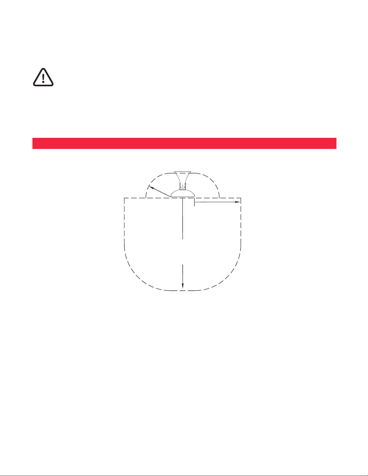
MOUNTING HEIGHT/CLEARANCES
CLEARANCE FROM COMBUSTIBLES:
MIN. 6" (15.2cm)
CLEARANCE
BEHIND HEATER
• For Wall-Mounting, do not install heater closer than 18" (45.7cm) from adjacent walls and 6" (15.2cm) from
ceiling and do not install less than 6' (1.8m) if the heater is labeled as UL Listed and 8' (2.4m) if the heater is
labeled as UL/CUL Listed from floor, while heater is set at a downward angle of 30 to 60 degrees.
• For Ceiling-Mounting, do not install heater closer than 18" (45.7cm) from adjacent walls and 6" (15.2cm) from
ceiling and do not install less than 6' (1.8m) if the heater is labeled as UL Listed and 8' (2.4m) if the heater is
labeled as UL/CUL Listed from floor, while heater is at a maximum 30 degrees.
MIN. 18" (45.7cm)
FROM SIDES AND
ENDS OF HEATER
MIN. 36" (91.4cm)
IN FRONT OF HEATER
• Adjacent Heaters to be installed no less than 3' (0.9m) apart.
• Do NOT operate within 25' (7.6m) of flammable/explosive material.
• Never block heater.
• Heaters greater than 240 Volts are for “Commercial Use Only. Risk of fire. Do not use as a residential or
household heater.”
• A means for disconnection of the appliance must be incorporated in accordance with the local wiring codes.
• Do not use if the heating element is damaged or cracked.
“IMPORTANT INSTRUCTIONS”
22
“SAVE THESE INSTRUCTIONS”
INSTALLATION INSTRUCTIONS
11/32" (0.9 CM) INSIDE NUT
SNUG TO CERAMIC
11/32" (0.9 CM) OUTSIDE NUT
This heater must be permanently installed and hard wired by a licensed electrician in accordance with local electrical
codes. Assembly procedure must be performed with no electrical power to unit.
Step 1: Check UL/CUL/CE label on heater for proper voltage.
Step 2: Follow supplied wiring instructions. (See wiring instructions below)
Step 3: Heater must be mounted with reflector angled down.
Step 4: All electrical connections must be in compliance with the National Electric Code (NEC) and local codes for
outdoor wiring.
Step 5: Use only wiring components UL/CUL/CE listed for outdoor use with IPX4 minimum rating.
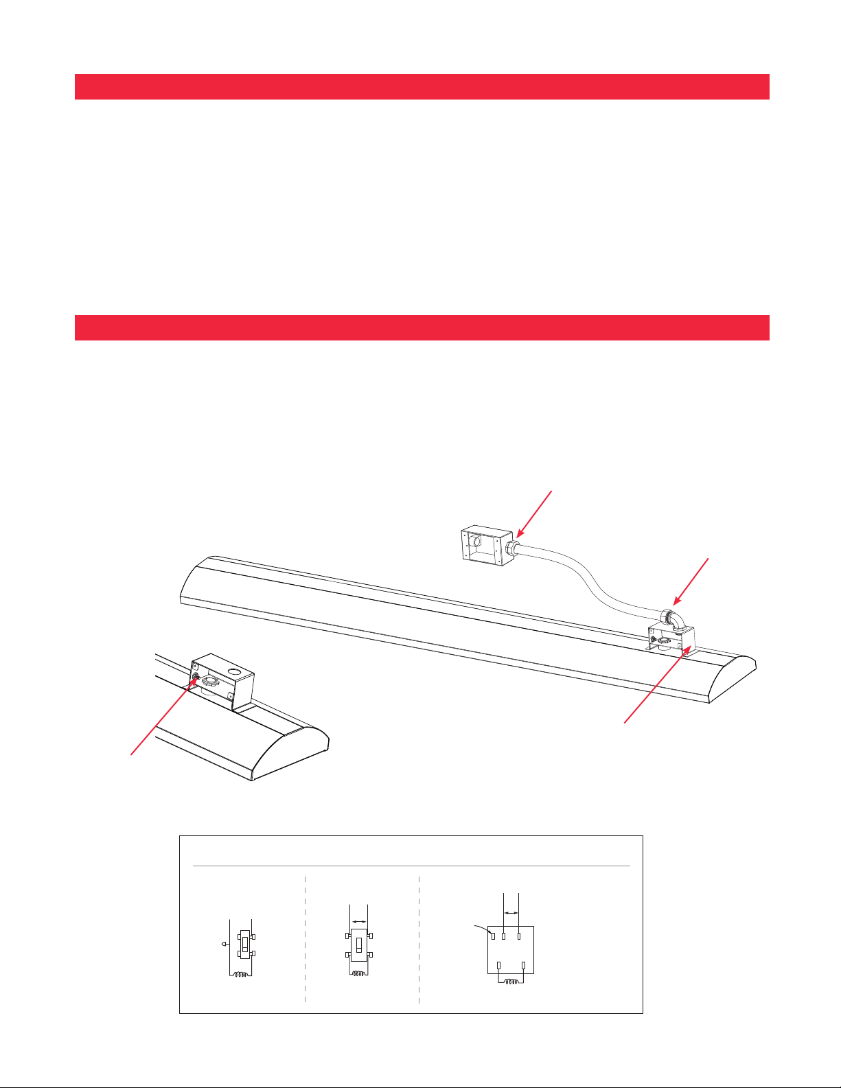
WIRING INSTRUCTIONS
The heater is drilled and threaded for standard 1/2" conduit fittings. The installing electrician will need to provide the
appropriate rigid metallic, flexible or liquid tight conduit for the installation location.
• Observe local electrical code regulations.
• Remove cover plate from junction box.
• Attach conduit.
• Use only copper wire suitable for 90°C.
• Replace cover plate.
Connect power with flexible
conduit or appropriate cord to
allow heater to be swiveled.
The Junction Box inlet hole is
sized for a standard ½” weather
tight conduit fitting and has a
locknut located on the inside of
the box for fastening.
GREEN GROUND
WIRE SCREW
TYPICAL WIRING OPTIONS
TYPICAL 120V WIRING
FOR A SINGLE POLE SWITCH
OFF
ON
BLACK 115 V.
WHITE
HEATING ELEMENT
TYPICAL 240V WIRING FOR
A TWO POLE SWITCH
240 V.
OFF
ON
HEATER
Junction Box on top of the heater
has a gasket side access cover.
WIRING FOR OPTIONAL 120V/240V CONTROLS
240 V.
FOR 115V. PILOT
LIGHT IF USED
REAR VIEW OF
CONTROLLER FOR
MAX. 15 AMP
LOAD ONLY
P L1 L2
HEATER
"TOP" MARKED ON
TOP
REAR OF CONTROL
MUST BE INSTALLED
H2H1
IN AN UP POSITION
3
 Loading...