

Aegis Micro NRC 2.0.1 User Manual
Networked Receiver Controller
NRC-2.0.1
Users’ Guide
th
11
October 2005
DUNS: 826771508
CAGE: 1RKF1
www.aegis-inc.net
Telecom Engineering Services & Products
8610 Washington Blvd. Suite 213 Jessup, MD 20794
240.568.9006 240.568.9008 [fax]

Proprietary Statement
All rights reserved. No part of this publication may be reproduced, stored in a retrieval
system, or transmitted, in any form by any means, electronic, mechanical, by
photocopying, recording, or otherwise without prior written permission.
Disclaimer
Information furnished in this manual is believed to accurate and reliable. However, no
responsibility is assumed for its use, or for any infringements of patents or other rights
of third parties that may result from its use.
Warning
This equipment utilizes voltages which are potentially dangerous and may be fatal if
contacted. Exercise caution when working with the equipment any time the protective
cover is removed.
Users’ Guide: Networked Receiver Controller - NRC-2.0.1 PAGE 2
11th October 2005 Copyright © 2005 Aegis, Inc wwww.aegis-inc.net [ph. 240-568-9006]

Table of Contents
General Information........................................................................................................................ 5
Channel Architecture..................................................................................................................6
Audio Data Capture .................................................................................................................... 6
Universal Receiver Translation/Abstraction............................................................................... 7
Capabilities Summary.................................................................................................................8
Receiver Controllable Settings ...............................................................................................8
Client Connection Options......................................................................................................8
Remote NRC System Monitoring...........................................................................................8
Digitized Audio Channel Output Options............................................................................... 8
Receiver Channel POST.........................................................................................................8
Network Time Protocol (NTP) Client..................................................................................... 8
Specifications..............................................................................................................................9
System Hardware.................................................................................................................... 9
Supported Receivers ............................................................................................................... 9
Physical Inputs/Outputs..........................................................................................................9
A/D Conversion......................................................................................................................9
Chassis .................................................................................................................................... 9
Support Software ....................................................................................................................9
Power ...................................................................................................................................... 9
Documentation........................................................................................................................9
Installation..................................................................................................................................... 11
Contents .................................................................................................................................... 11
Hardware Installation................................................................................................................ 12
Step 1: Receiver Audio Signal Termination Type.............................................................. 12
Step 2: Rack Mount the NRC unit...................................................................................... 12
Step 3: Connect Power........................................................................................................ 12
Step 4: Connect Receivers..................................................................................................12
Step 5: Optional - Connect an External Clock.................................................................... 12
Step 6: Connect to the Network.......................................................................................... 12
NRC Configuration...................................................................................................................13
Prerequisites:......................................................................................................................... 13
Step 1: Connect to the NRC................................................................................................ 13
Step 2: Change Administrator Password............................................................................ 14
Step 3: Configure Network Settings...................................................................................15
Step 4: Set the Time and Date............................................................................................. 15
Step 5: Configure the Network Time Daemon (Optional)..................................................16
Step 6: Set the Host Name..................................................................................................17
Step 7: Restart the NRC......................................................................................................17
Step 8: Configure the NRC for Receivers...........................................................................19
Operation....................................................................................................................................... 20
Using the NRC..........................................................................................................................20
Starting the NRC................................................................................................................... 20
Interpreting the LCD Display............................................................................................... 20
Requirements ........................................................................................................................ 22
Running the NRC Java Client............................................................................................... 22
Users’ Guide: Networked Receiver Controller - NRC-2.0.1 PAGE 3
11th October 2005 Copyright © 2005 Aegis, Inc wwww.aegis-inc.net [ph. 240-568-9006]

Connect to NRC Server Dialog............................................................................................. 22
The Main Application Window............................................................................................23
Change Receiver Model Dialog............................................................................................ 31
Change Antenna Model Dialog ............................................................................................ 32
NRC Properties Dialog.........................................................................................................33
Capture Channel Data Dialog............................................................................................... 34
Signal Display Dialog........................................................................................................... 35
Appendix A - Receiver Configuration.......................................................................................37
BAE Systems WJ-8723............................................................................................................. 37
TEN-TEC RX-331.................................................................................................................... 37
Appendix B - Software Upgrades .............................................................................................38
NRC File System...................................................................................................................... 38
UPDATE Command................................................................................................................. 39
RESTORE Command............................................................................................................... 39
CLEAN Command.................................................................................................................... 40
Upgrade Procedure....................................................................................................................40
Users’ Guide: Networked Receiver Controller - NRC-2.0.1 PAGE 4
11th October 2005 Copyright © 2005 Aegis, Inc wwww.aegis-inc.net [ph. 240-568-9006]
E C E I V E R
General Information
The Networked Receiver Controller (NRC) is a single node network device capable of
simultaneously:
• controlling and configuring up to 8 attached receivers for data collection
• collecting and digitizing each receiver’s analog audio output signal
• formatting and routing the digitized receiver’s signal to an attached network client.
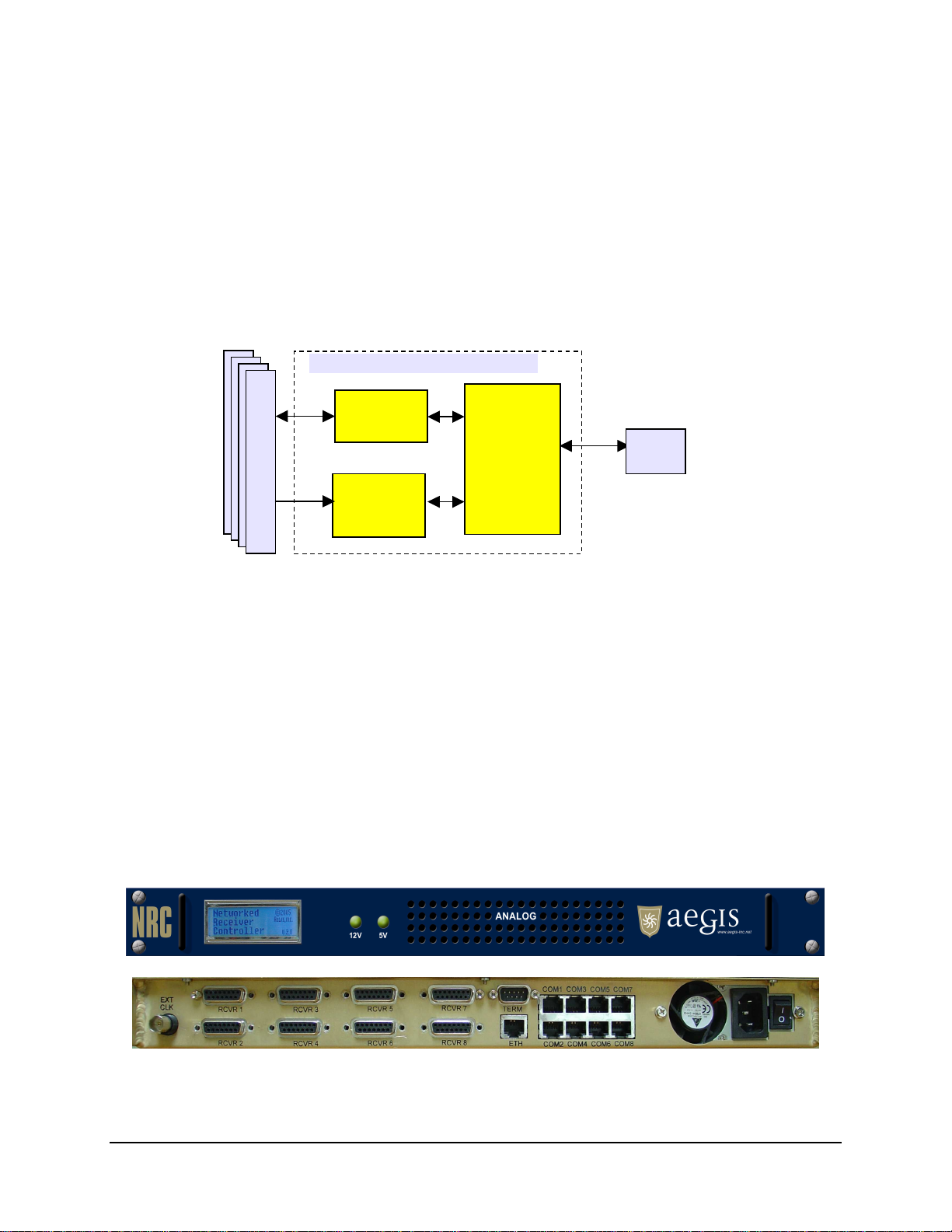
A simple diagram of the NRC system is shown below.
R
S
Networked Receiver Controller
CONTROL
DATA
CPU
NRC
Client
The NRC represents the server portion of a network based client/server architecture. NRC clients
connect and disconnect from the NRC via an Ethernet network connection as necessary. When
connected, a client has the ability to control, configure and collect digitized audio data from the
associated receiver.
Each receiver is physically connected to the NRC via an RS-232 command/control port and an
audio input port. The receiver’s analog audio output is connected to an A/D where it is sampled
at 16 KHz with 16 bit resolution. The resultant digitized audio signal is available for secondary
processing and distribution from the NRC as required. The default NRC configuration provides a
4 KHz band-limited, 8 KHz sampled data signal. This digital audio signal is available to the
NRC client through a simple packet based protocol, which aggregates samples into a single data
packet for forwarding to the client.
The NRC server is a 1 rack unit chassis system with the following front and back views.
In this chapter, the various features of the NRC will be discussed.
Users’ Guide: Networked Receiver Controller - NRC-2.0.1 PAGE 5
11th October 2005 Copyright © 2005 Aegis, Inc wwww.aegis-inc.net [ph. 240-568-9006]

Channel Architecture
A channel defines a virtual connection between a client application and a receiver connected to
the NRC.
There are two types of channel connections which can be established to a receiver; a Primary
connection and a Piggy-back connection.
1. A Primary Connection
a. A Primary connection is established with a receiver when the receiver is free of
any other client connections.
b. A Primary connected client has full access and control of the receiver and its
resources.
2. Piggy-back Connection
a. A Piggy-back connection is established with a receiver when the receiver
currently has one or more other clients already attached to it.
b. A Piggy-back connected client cannot change any of the receivers settings,
although it can view the current receiver settings, and capture and format the
receivers audio output.
The NRC supports one Primary connection per receiver and multiple Piggy-back connections,
with the NRC able to support an aggregate of 64 simultaneous Primary/Piggy-back connections.
Audio Data Capture
The NRC uses an 8 channel PCI-based Analog/Digital converter card to digitize each receiver’s
audio output signal. Each receiver’s audio signal is digitized into 16-bit samples (14.8 effective
bits/sample) at a sampling rate of 16 KHz.
Each client attached to the receiver can receive a copy of this sampled audio data through a
simply packet based protocol, and can specify:
• the number of samples to be contained within a data packet
• the effective sampling rate of the data - either 8 KHz or 16 KHz.
• the audio data filtering option – 4 KHz LPF ON or OFF, and
• the packet time stamping – TAI64N ON or OFF
Sampling synchronization is achieved either via the NRC’s internal high precision crystal
oscillator circuitry or by a user provided external clock signal into the NRC’s EXT CLK port.
The user external clock signal, if used, should be a 50% duty cycle (TTL) square wave operating
at a frequency of 16 KHz.
Users’ Guide: Networked Receiver Controller - NRC-2.0.1 PAGE 6
11th October 2005 Copyright © 2005 Aegis, Inc wwww.aegis-inc.net [ph. 240-568-9006]

Universal Receiver Translation/Abstraction
The NRC abstracts the user from each receiver’s proprietary low-level communications protocol
by presenting a common receiver translation software tasking interface to the user. This common
software interface allows the user to task the receivers at a logical level without the need to
worry about how to implement this tasking. This allows a wide range of different receivers to be
tasked via the NRC in the same manner regardless of the number, model or configuration of the
receivers.
This receiver hardware abstraction allows the NRC:
• To be easily programmed to connect to almost any receiver with an audio output.
• To accommodate being connected to different receiver models simultaneously.
• To control the major functions of any receiver through a simple tasking protocol.
• To provide receiver vendor independence, allowing the user to utilize the most
appropriate receiver for any given application.
Receiver XML configuration files are used to define the different receiver protocol profiles. This
allows new receiver support to be added to the NRC relatively quickly and simply by generating
and integrating a new receiver XML profile file.
A list of currently supported receivers can be found in the specifications section of this
document, with additional receiver support able to be provided upon request.
Users’ Guide: Networked Receiver Controller - NRC-2.0.1 PAGE 7
11th October 2005 Copyright © 2005 Aegis, Inc wwww.aegis-inc.net [ph. 240-568-9006]

Capabilities Summary
Receiver Controllable Settings
• Frequency
• Detection Mode
• IF Bandwidth
• AGC mode
• BFO
• Reset / Reboot
• Pass native commands to the receiver
o By-pass the generic receiver
interface and send the receiver
proprietary commands
• Receiver Memory Interface Support
o Save, recall and query receiver
configuration memory settings
Remote NRC System Monitoring
• View current state of receiver configurations
and attached clients
• View health and well being of NRC
Client Connection Options
• Up to 64 simultaneous client connections
• Primary - connection to a receiver when it is free
o Full control and access to the receiver, the
audio data and its configuration options.
• Piggyback - connection to a receiver that already has a
Primary client attached
o Limited connection privileges
o No control of the receiver but visibility of the
receiver’s settings.
o Full access to the receiver’s audio
configuration and data options.
o Can be promoted to Primary connection status
if the existing Primary client disconnects
Digitized Audio Channel Output Options
• Sampling Rate: 8 KHz (default), 16 KHz
• Filtering: 4 KHz LPF (default), None
• Samples/Data Packet: 640 (default), 128-4096
• Packet Time Stamping: None (default), TAI64N
• Retune Samples skipped: 350 (default), variable
• Collection Control: Start / Stop
Receiver Channel POST
• A power on self test is used to verify each
receiver’s RS-232 control and audio signal
paths to reduce the possibility of incorrectly
connecting receiver cables
Network Time Protocol (NTP) Client
• The NRC is configurable to obtain and synchronize
time with an NTP Server
Users’ Guide: Networked Receiver Controller - NRC-2.0.1 PAGE 8
11th October 2005 Copyright © 2005 Aegis, Inc wwww.aegis-inc.net [ph. 240-568-9006]

Specifications
System Hardware
• CPU System:
o PC x86 SBC based system
• Operating System
o Linux OS, Compact Flash based file
system
Physical Inputs/Outputs
• Number of controllable receivers: 1 to 8
• Connections/Receiver
o 1x Audio Input Port (DB-15)
o 1x Control Port (RJ-45, RS-232)
• Network Port (RJ-45, 10/100 Base-T Ethernet)
• Remote Serial Terminal Port (DB-9, RS-232)
• External A/D Card Clock Input (BNC, TTL)
Chassis
• 1RU (19”x 20”x1.75”), fits standard 19” racks
• Jonathan 375QD-20 slide mounts fitted
• Weight: 10lbs
• Ventilation: Positive internal pressure
• Internal Heating Profile:
o Fully loaded NRC, temperature increase
<+15F above ambient
Note: Chassis not recommended to be solely mounted
in 19” rack by bolts through the chassis’ front panel
- rack slides or rack shelving recommended.
Supported Receivers
• DRS WJ-8723 HF Receiver
• Ten-Tec RX-331HF Receiver
• Additional Receivers available upon request
A/D Conversion
• Sample Resolution:
o 16-bit (14.8 effective bits)
• Channel Sampling Rate: 16 KHz
• Pre A/D Channel Gain: 1 (default), 2, 4, 8
• Internal Sampling Clock
o Accuracy: 10ppm 0-85C
o Stability: 10ppm 0-85C
• External A/D Card Clock Input
o 16 KHz TTL square-wave: 50% duty-cycle
o Optional input to provide external sync
• Analog Signal Input
o Range: -5V to +5V
• Types: Single-Ended / Differential
Support Software
• Java and C++ programming APIs
• Example Client Program
• Remote software upgrade capability
Power
• Nominal power: 25 W
• Max power: 32 W
• Operating Range:
o 100-240 VAC, @47-63Hz (Auto-Select)
Documentation
• Programmers Manual
• Users Manual
• Protocol Interfacing Document
Users’ Guide: Networked Receiver Controller - NRC-2.0.1 PAGE 9
11th October 2005 Copyright © 2005 Aegis, Inc wwww.aegis-inc.net [ph. 240-568-9006]

Users’ Guide: Networked Receiver Controller - NRC-2.0.1 PAGE 10
11th October 2005 Copyright © 2005 Aegis, Inc wwww.aegis-inc.net [ph. 240-568-9006]

Installation
Contents
The following is a list of items delivered with the NRC unit.
• Networked Receiver Controller unit (1)
• Power cable (1)
• Receiver Control Cables (8)
o For BAE Systems WJ-8723 units - 8x DB25M-RJ45 - grey cables
o For TenTec RX331 units - 8x DB25M-RJ45 - black cables
• Receiver Audio Cables (8)
o For BAE Systems WJ-8723 - 8x DB15M/DB15M audio cables
o For TenTec Rx331 units - 8x DB15M/DB15M audio cables
• Users’ Guide (1)
• Programmers’ Guide (1)
• Documentation and SDK CD (1)
Users’ Guide: Networked Receiver Controller - NRC-2.0.1 PAGE 11
11th October 2005 Copyright © 2005 Aegis, Inc wwww.aegis-inc.net [ph. 240-568-9006]

Hardware Installation
Step 1: Receiver Audio Signal Termination Type
The NRC supports both differential and single-end audio signals, with the factory system default
being configured to support Differential Mode.
If Single-End mode is required, proceed as follows:
1. Ensure the NRC is powered off
2. Remove the top cover of the NRC.
3. Locate the two banks of 4x DIP switches, D1 and D2.
4. Set all switches to the ON position for single-ended operation.
a. Conversely, set each switch to the OFF position for differential operation.
5. Replace the cover and install the screws.
Note: The NRC software’s default configuration is to support Differential Mode,
and hence it must also be configured to match the desired audio signal state. The
NRC Configuration section will address this requirement.
Step 2: Rack Mount the NRC unit
The NRC chassis supports Jonathan Type 375QD-20 chassis slides and these are recommended
for rack mounting the NRC where necessary.
Note: It is not recommended that the NRC Chassis be solely mounted in 19” rack by bolts
through the chassis’ front panel - rack slides or rack shelving recommended.
Step 3: Connect Power
The supplied power cable should connect the power adapter on the back panel power socket of
the NRC. The NRC power supply is an auto-sensing unit which can accept voltages between
100-240VAC @47-63Hz.
Step 4: Connect Receivers
Each brand and model of receiver has specific configuration and installation instructions that
must be followed prior to operation with the NRC. Please refer to Appendix A.
Step 5: Optional - Connect an External Clock
If an external clock connection is desired for A/D synchronization, use a coaxial cable to connect
a 16 KHz TTL (50% duty cycle) external clock signal to the EXT CLK port on the NRC’s back.
The NRC’s default configuration uses the internal clock and hence the system needs to be reconfigured to use an external signal for A/D synchronization. This can be achieved after the
Hardware Installation through the NRC Java client’s “Global NRC Properties” dialog, or via the
programmers’ SDK.
Step 6: Connect to the Network
A Cat-5 cable should be used to connect between the ETH port on the back panel of the NRC
and the local area network.
Users’ Guide: Networked Receiver Controller - NRC-2.0.1 PAGE 12
11th October 2005 Copyright © 2005 Aegis, Inc wwww.aegis-inc.net [ph. 240-568-9006]

NRC Configuration
Prerequisites:
In order to successfully configure the NRC for operational use, the installer must have access to:
a. a terminal emulation program
i. Before using it on the network the NRC must be properly configured, by
running a configuration utility on the NRC through a remote terminal
session. This requires connecting serially to the NRC from another
computer. The operating system of the computer is not important as long
as it has a compatible terminal emulation program. For example, most
Linux distributions contain minicom and the Windows systems contain
HyperTerminal, both of which are appropriate for this application
requirement. In addition, the computer must contain an available serial
port.
b. A computer machine on which the NRC java client can be run
i. In order to configure the NRC to understand the type of attached receivers,
the supplied NRC Java client needs to be able to run. This computer needs
to be on the same network as the NRC unit so it can attach to the NRC.
Step 1: Connect to the NRC
Before using it on the network the NRC must be properly configured, by running a configuration
utility on the NRC through a remote terminal session. This requires connecting serially to the
NRC from another computer. The operating system of the computer is not important as long as it
has a compatible terminal emulation program. For example, most Linux distributions contain
minicom and the Windows systems contain HyperTerminal, both of which are appropriate for
this application requirement. In addition, the computer must contain an available serial port.
The following steps describe the remote terminal connection process:
1. Power on the NRC
2. Connect a DB9 null modem cable from the remote terminal port on the NRC to a serial
port on the computer.
3. Start the terminal emulation application on the computer.
4. Specify correct terminal settings on the terminal emulation application. Please refer to
the application documentation for instructions on how to make these settings.
• COM Port: use the serial port on the computer that connects to the NRC.
• Bits per second: 9600
• Data bits: 8
• Parity: none
• Stop bits: 1
• Flow control: None
• Terminal emulation: vt100
5. Activate the terminal (press Enter a few times). You may need to send a terminal break
if this doesn’t work.
6. Once this terminal is active the linux system and NRC boot-up messages will be echoed
to the remote terminal. Once the NRC system has finished booting, a user login prompt
will appear.
Users’ Guide: Networked Receiver Controller - NRC-2.0.1 PAGE 13
11th October 2005 Copyright © 2005 Aegis, Inc wwww.aegis-inc.net [ph. 240-568-9006]
 Loading...