

Page 1
Manual
for ARE K1/PFB
Installation Guide
Due to Systems with
Profibus-DP Interface
Page 2
Contents
1 INTRODUCTION ............................................................................................................ 4
2 SYSTEM OVERVIEW .................................................................................................... 4
3 PROJECT PLANNING ................................................................................................... 5
4 START-UP PROCEDURE ............................................................................................... 6
5 INSTALLATION ............................................................................................................. 7
5.1 Mounting of the Housing ........................................................................................................................... 7
5.2 Grounding of the Reader Box .................................................................................................................... 8
5.3 Making of the Cable Connections .............................................................................................................. 8
5.3.1 Allowed Diameter of the Used Cables .................................................................................................. 8
5.3.2 Assembling of the Cable Pipe .............................................................................................................. 8
5.3.3 Mounting of the Power Supply Cable .................................................................................................. 9
5.3.4 Final Assembly of the Cable Pipe ........................................................................................................ 9
5.3.5 Plug in of the SAB Cab .................................................................................................................... 10
5.3.6 Connection to the Power Supply ....................................................................................................... 10
5.3.7 Connection characteristics of the digital inputs.................................................................................. 10
5.3.8 Connection to the Antenna ................................................................................................................ 10
5.3.9 Assembling of the Data Cable (Profibus Network) ............................................................................. 11
5.3.10 Plug in of the Profibus SAB Cabs ..................................................................................................... 12
6 DEFINITION OF THE PROFIBUS SLAVE ATTRIBUTES ............................................ 12
6.1 Operation at the End of a Network Line .................................................................................................. 13
7 INITIAL OPERATION .................................................................................................. 13
7.1 Indicators ................................................................................................................................................ 14
8 INTEGRATION INTO THE PROFIBUS NETWORK ...................................................... 14
8.1 Profibus Slave: Configuration and Parametrization ................................................................................ 15
--------------------------------------------------------------------------------2/18--------------------------------------------------------------------------------
Page 3

9 MODES OF OPERATING AND COMMANDS OF THE READER ................................... 15
9.1 Set of Commands .................................................................................................................................... 15
9.2 Operating mode 2 - Reading Triggered by the PLC .................................................................................. 16
9.2.1 Principle of Reading a Transponder in mode 2 .................................................................................. 16
10 WARNING NOTES .................................................................................................... 16
11 FCC INFORMATION ................................................................................................. 17
12 DOCUMENTATION, REFERENCES .......................................................................... 18
13 CONTACTS ............................................................................................................... 18
14 NOTIFICATION OF CHANGES .................................................................................. 18
2001 by AEG Identifikationssysteme GmbH
All rights reserved. All product names are registered trademarks of the corresponding owner.
--------------------------------------------------------------------------------3/18--------------------------------------------------------------------------------
Page 4
1 Introduction
This document will describe the components of the reader system ARE K1 / PFB and the procedure
how to do the set up of the reader. The main features of the reader are listed below:
• algorithms to read Trovan und PSK1-transponders
• the Profibus-DP-interface is opto-isolated and placed inside of the housing, allowed baud rate are
up to 12MBit/s
• the node address of the reader can be chosen from 2 to 99, using adress switches which can be set
without opening the housing
• the allowed supply voltage is 18 to 28VDC (typical 24V)
• The reader is equipped with an galvanic disconnected digital input. The positive edge causes a
trigger signal. The input voltage is 24 V.
• low power consumption of reader < 24Watt
• high reliability for reading within an industrial environment.
• reading distance using the ID 200 transponder and the AAN FK2 antenna:
- 40 cm in static application
- 30 cm when transponder is moved with up to 10m/min
• different antenna types available to meet special application demands
• fully compatible with Compact reader system ARE I2 / PFB
• the cabling concept of the reader is optimised to service demands.
• the protection class of the housing is IP65
• ambient temperatur limit: -20 to 70 °C
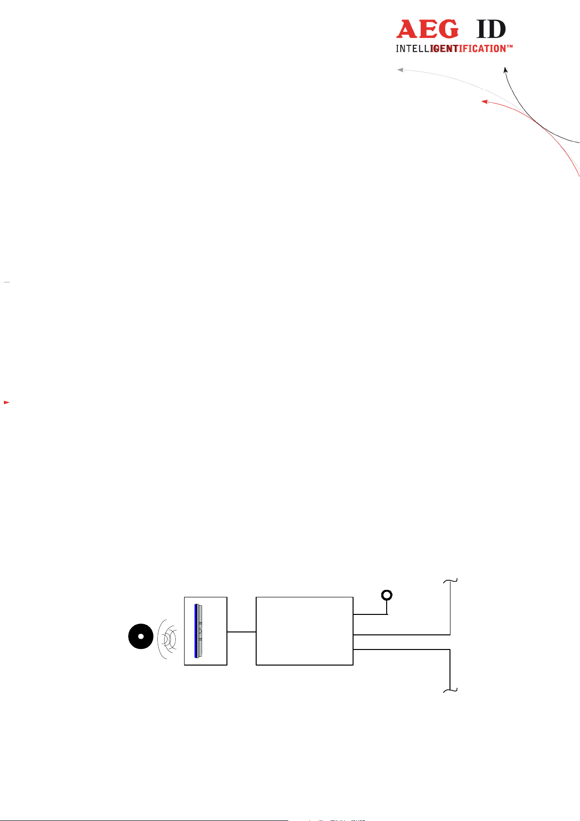
2 System Overview
The reading systems consists of two modules (see Figure 2-1)
• the reader box ARE K1/PFB and
• the active antenna (i.e. AAN FK2)
By means of the active antenna the reader generates an alternating magnetic field, which powers the
transponder. Coded signals sent back from the transponder are received and decoded by the reader.
transponder
Figure 2-1: Concept of the Reading System
The reader is fully controlled by an Profibus-Master while using the integrated Profibus interface.
24V
DC
reader
antenna
ARE K1/PFB
Profibus DP
--------------------------------------------------------------------------------4/18--------------------------------------------------------------------------------
Page 5

The antenna must not be brought next to a metal surface. This could lead to a significant change of
the properties of the antenna circuit, which in turn reduces the reading range considerably. Please
take account to the installation manual of the antenna!
Environmental electromagnetic noise may also reduce the specified reading performance.
Special hints to overcome these problems are documented in chapter 3 and in the installation manuals
of the antenna.
The antenna is connected to the reader by the antenna cable. The typical length of the cable is 5 m.
3 Project Planning
For proper function of the identification system attention should be paid to the mounting of antenna
and antenna cable according to the rules, pointed out in the installation manuals of the antenna and
the reader.
Make shure that the reader box is grounded. Otherwise the reading distance can be reduced significantly and the electronics can be damaged by electrostatic discharge.
To get reliable readings, the distance between reader and transponder must be within the specified
reading volume.
The reading characteristic in front of the antenna is not isotropic. To get the maximum reading distance, the orientation between antenna and transponder must be well suited. The best orientation depends on the type of antenna. Please take attention to the installation manual of the antenna.
To get reliable reading performance, the time of the transponder while crossing the sensitive area of
the antenna must be co-ordinated to the data transfer characteristics of the transponder. In general
the time depends on the speed of the transponder, the size of the transponder and the way the transponder is mounted on the vehicle and must be verified by field tests.
Environmental electromagnetic noise may also reduce the read range considerably.
Arrangement to eliminate such troubles must be done specific to the application by the help of engineers of the manufacturer.
--------------------------------------------------------------------------------5/18--------------------------------------------------------------------------------
Page 6
t
Slave attributes
check powe
r consumption and LEDs
uration
between master and slave
fer
9.2
8 build application
realise function modules on the plc
-
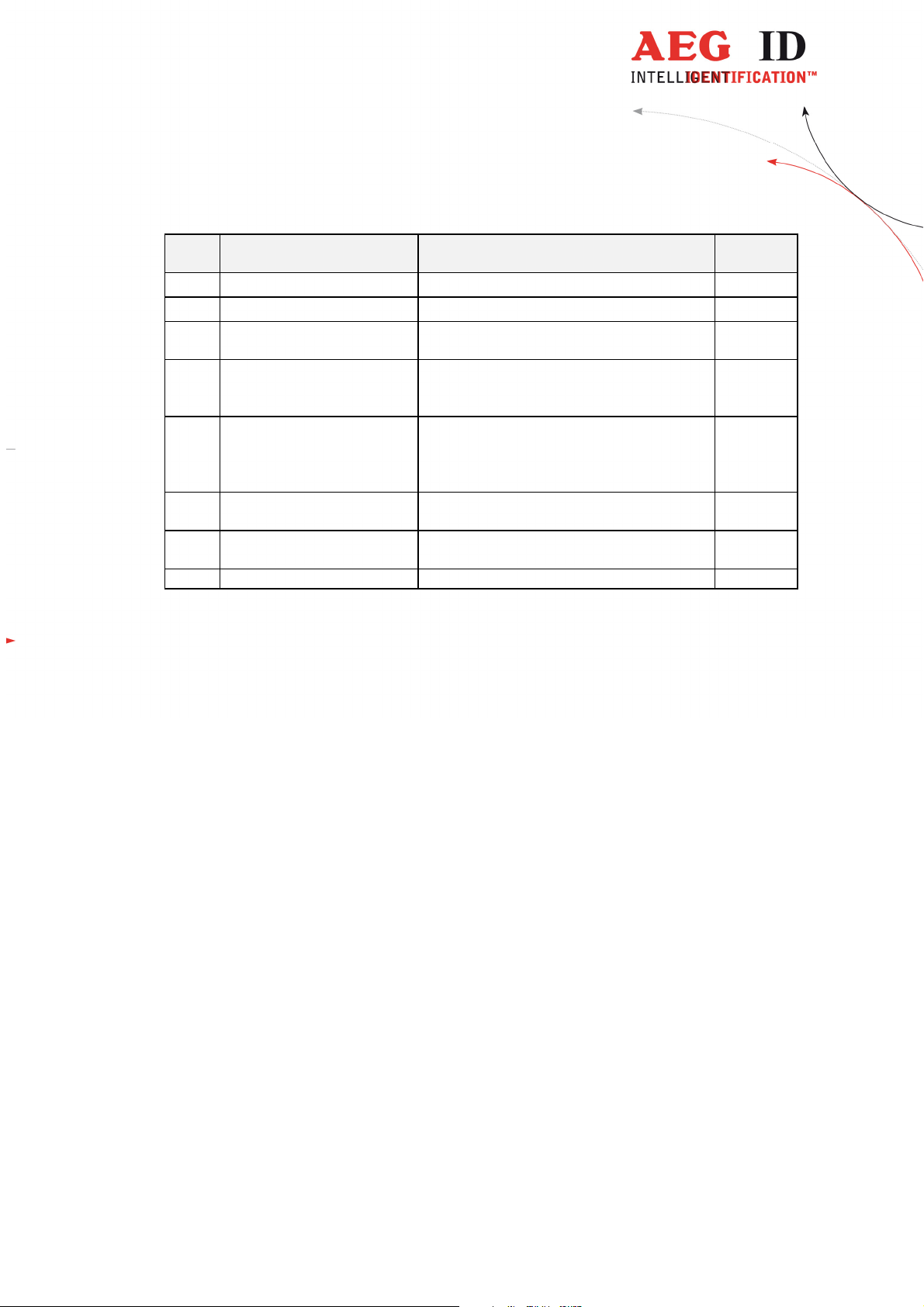
4 Start-up Procedure
Schrit
Aufgabe Inhalt Verweis
1 prearrangements read installation manuals carefully -
2 installation mounting, cabeling chapter 5
3 definition of the Profibus-
4 initial operation connect antenna
set node adress and termination switch chapter6
chapter7
switch on power supply
5 integration into the Profi-
bus-network
read GSD into the plc, integrate ProfibusSlave with correct slave adress,
chapter 8
send telegrams with parameters and config-
6 implement data transfer
realise basic function module for data trans-
see [2]
7 check system send reading command, check reaction chapter
--------------------------------------------------------------------------------6/18--------------------------------------------------------------------------------
Page 7

5 Installation
To get the specified reading performance it is necessary to do the installation carefully step by step as
it is described in the chapters below. All the work must be done by well educated people.
5.1 Mounting of the Housing
The reader box of the ARE K1/PFB has connection ports for:
• the antenna [ANT]
• the power supply [24VDC]
• Profibus input [Profibus]
• Profibus output [Profibus]
• ground
LED-indicators
T
N
A
D
A
E
R
o
P
O
N
R
R
E
X
R
X
T
top of the box
bottom of the box
Abbildung 5-1: Configuration of the ARE K1/PFB
The reader can be mounted to any other mechanic construction. It is recommended to protect the
housing against heavy mechanical interactions.
D
I
g
n
u
H
e
g
l
h
o
F
c
f
s
r
i
e
B
B
n
o
V
r
F
t
d
k
n
e
P
l
u
/
e
g
e
n
1
n
u
r
n
e
n
K
d
e
o
k
r
M
e
E
t
k
e
R
j
b
O
A
s
u
b
i
f
o
r
P
s
u
b
i
f
s
o
u
r
b
P
i
D
A
E
R
E
T
I
R
W
C
D
V
4
2
f
o
r
P
s
u
b
i
f
o
T
r
N
P
A
T
N
A
C
D
V
4
2
SAB connector
caps
ground connector
The reader can be mounted on a plate using the holes in the box. To get access to this holes the top of
the box has to be demounted. It is recommendable to remove all connecting cables before. The electronic components mounted in the top of the box are connected to the reader electronics in the bottom
of the box. All connecting cabels are pluggable at the bottom side. When disconnecting the plugs
catch hold of the plug - not of the cable!
After mounting the bottom of the box it has to be paid attention to make all connection between top
and bottom electronics in the right way again. All plugs are safe to wrong polarity.
--------------------------------------------------------------------------------7/18--------------------------------------------------------------------------------
Page 8

Attention!
While closing the box take cake, that no cables are shut between top and bottom of the box. In addition the seal ring in the top of the box has to be checked, to ensure tightness of the box.
5.2 Grounding of the Reader Box
To get reliable reading results, the reader must be grounded. The connector is placed at the side of the
housing (6.35 mm flat contact). To avoid problems with electromagnetic compatibility, the cable to
ground ought to be very short with low impedance.
Attention!
The topology of the ground wires must be done in the right way (according state of art).
Attention!
Make always shure that the reader box is grounded. Otherwise the reading distance can be reduced
significantly.
5.3 Making of the Cable Connections
The cable connections are realised with help of the SAB cabs. The mounting of the cabs is discribed
detailed in the following subchapters 5.3.1 to 5.3.10.
5.3.1 Allowed Diameter of the Used Cables
The allowed diameters of the cables used for data link and power supply must be in the range from
∅3,5 to ∅8mm. For this case, IP 65 is reached.
5.3.2 Assembling of the Cable Pipe
• Breakthrough the prepared areas at the surface of the SAB cabs. There are two prepared areas
seen at the SAB cab: central and at one side of the cab.
• The sealing must be done in the correct way O-ring (3) at the cable pipe (4) (see also Figure 5-2.
2
Figure 5-2: Assembling of the Cable Pipe
1
4
3
• Bring the nut (2) of the cable pipe inside of the SAB cab (1).
• To fasten the nut please use the right tool (17mm).
--------------------------------------------------------------------------------8/18--------------------------------------------------------------------------------
Page 9

5.3.3 Mounting of the Power Supply Cable
The power supply cable must be mounted in following steps:
• Prepare the SAB cab according to chapter 5.3.2
• Remove all inner parts from the cable pipe at the SAB cab (1) ( nut (5), pipe(4) and cable fasten-
er (3)) (see Figure 5-3)
• Put all the removed parts ( nut (5), pipe (4), cable fastener (3)) and the cable pipe of the SAB cab
4
3
5
Cable
as well (1 to 4) to the cable.
Figure 5-3: Arranged Parts for Mounting of the SAB Cab
6
• Remove the outer isolation of
the cable at a length of 6cm .
1
7
• Remove the isolation of the
wires at a length of 6 [mm] and
stick a covering hull to the litz
wire.
• Put the cable through the cable
pipe. The length of the cable coming out the SAB cab must be long enough to do all further installation steps in an easy way.
• Stick the pipe (4) into the cable fastener (3).
• Stick the cable fastener (3) into the cable pipe.
• Connect the power supply cable into the right places of the MINI-COMBICON-connector (see Fig-
ure 5-3 Part (6)).
• The pin assignment is shown in the figure below.
not used
not used
not used
not used
not used
not used
+24V
DC
0V / GND
( Dig-In + )
( Dig-In - )
+U
S
blue
-U
S
L
U
L
24VDC
brown
blue
Figure 5-4: Pin Assignment for Power Supply Cable
5.3.4 Final Assembly of the Cable Pipe
• Plug the finished assembled MINI-COMBICON-connector to the SAB cab. Take care of the cor-
rect coding ((7) in Figure 5-3) of the connectors.
• Pull by and by all the cable back, until the isolation of the cables are near to beginning of the ca-
ble pipes.
--------------------------------------------------------------------------------9/18--------------------------------------------------------------------------------
Page 10

• Fasten nut (5) of the cable pipes with the right tool (17mm).
• Do this carefully, to ensure the tightness of the protection class of IP 65.
5.3.5 Plug in of the SAB Cab
Attention !
Before plugging the SAB cab to the connectors of the reader, make sure that the grounding of the
device is well done. Otherwise the electronic may be destroyed by electrostatic discharge.
1
2
A
1
B
Figure 5-5: Plug-in of the SAB Cab
• Put on the sealing ( (2) in Figure 5-5 ) to the SAB cab (A).
• Plug in the SAB cab to the connector at the bottom of the reader box (B).
• There is only one way to plug in the SAB cab to the connector rim of the reader.
• Fasten the SAB cab with the help of the screws.
A
2
5.3.6 Connection to the Power Supply
Use a power supply of 24VDC. A current of aprox. 1,0 A is needed in full operation mode.
5.3.7 Connection characteristics of the digital inputs
The reader is equipped with an galvanic disconnected digital input. The positive edge
causes a trigger signal. The input voltage is 24 V.
5.3.8 Connection to the Antenna
The antenna is connected to the port ANT of the ARE K1 / PFB using the provided antenna cable. Inside the cable signals of a very small amplitude are conducted, so attention should be paid, that no interfering signals are coupled in. So don't use cabel tranch with other cables.
Best results will be produced using the original cables of AEG ID. This cables are ready to use and are
ideal fitted to the system regarding shielding and capacity of the cable.
--------------------------------------------------------------------------------10/18--------------------------------------------------------------------------------
Page 11

5.3.9 Assembling of the Data Cable (Profibus Network)
The connection from the ARE K1 / PFB to the master PLC is made using the interface cable. This
must be mounted in following steps:
• Prepare the SAB cabs "Profibus" in the same way like subchapter 5.3.2 .
• Put all the removed parts ( nut (5), pipe (4), cable fastener (3)) and the cable pipe of the SAB cab
as well (1 to 4) to the cable.
3
8
6
Figure 5-6: Arranged Parts for Mounting
1
7
5
4
Cable
• Remove the outer isolation of the cable at a length of 6 cm.
• Unwrap the texture of the shielding and drill it to build up pig tail wire (7).
• Stick a covering hull to the pig tail wire.
• Put the cable to the cable pipe. The length of the cable coming out the SAB cab must be long
enough to do all further installation steps in an easy way.
• Remove the isolation of the data wires at a length of 6 [mm].
• drill red litz wire of the data cable and put on a covering hull.
• do the same way with the green litz wires.
• Stick the pipe (4) into the cable fastener (3).
• Stick the cable fastener (3) into the cable pipe.
nc
nc
nc
nc
nc
shield
nc
+Data ( B )
-Data ( A )
nc
KHJFG
grey
Profibus
red
Figure 5-7: Pin Assignment for the Profibus-Net Data Cable
green
• Connect the data cables into the right places of the MINI-COMBICON-Connector.
• The pin assignment is shown in the Figure 5-7 at top.
• Continue according to subchapter 5.3.4
--------------------------------------------------------------------------------11/18--------------------------------------------------------------------------------
Page 12

5.3.10 Plug in of the Profibus SAB Cabs
Attention!
Before plugging the Profibus SAB cabs to the connectors of the reader, make sure that the grounding of the device is well done. Otherwise the electronic may be destroyed by electrostatic discharge.
6 Definition of the Profibus Slave Attributes
Before bringing the ARE K1 / PFB into operation in the Profibus net, the adress of the slave has to be
adjusted. If the reader is used at the end of a line, then the termination switch has to be set into the
"On" position in addition.
All control elements for the definition of the Profibus atributes are displayed in the figure below. Due
to the fact that all control elements are placed in the SAB ports they are accessible without opening
the housing.
n
O
n
o
i
t
a
n
i
m
r
e
t
f
f
O
1
0
x
0
1
0
x
ANT24VDC
Profibus Profibus24VDC ANT
The switch for activation the termination is situated in the left Profibus port. The positions for the
"On" and "Off" states are marked on the on the surface of the printed circuit board (PCB).
Attention!
Make shure, that only one device inside of a network line is terminated.
The switches to adjust the node adress are placed in the right Profibus port. The quality rating of the
singgle switches ( X1 resp. X10 ) are marked on the surface of the PCB. To make operative a new
adress node adjustmant it is essential to reset the ARE K1/PFB. This can be done very easily by shorttime breaking of the power supply.
--------------------------------------------------------------------------------12/18--------------------------------------------------------------------------------
Page 13

6.1 Operation at the End of a Network Line
If an ARE K1/PFB is used at the end of a network line, the termination has to be activated as described in the previous subchapter. In this device only one data cable is connected to the reader box. It
is indifferent, which one of the both ports is used for the data cable. To ensure the tightness of the the
protection class of IP65 the port unused has to be closed with a plain SAB cab.
7 Initial Operation
Before switching on the power supply following steps have to be done:
• Make full cabelling due to Figure 2-1
• Connect an active antenna AAN FKx at the end of the antenna cable, the antenna will be pow-
ered by the reader device. Don't bring the antenna close to metall or other antennae!
• Connect the power cable to the power supply. Pay attention for right polarity!
• Switch on power
• The typical stand by current is 140 ... 170 mA in triggerd (MD 2) operating mode.
• The LED indicator "OP" has to blink, the LED indicator "BusFail" 1 has to be on (for position of
the indicators see subchapter 7.1)
1
The indicator "BusFail" is on as long as the devi ce is not configurated and not parametrized. In this state no data transfer is possible between slave
and master. If the device is successfully configurated and not parametrized, then the i ndicator "BusFail" will switch off and the indicator "Run" will
swich on. This signalizes the possibi lity to tranfer data.
--------------------------------------------------------------------------------13/18--------------------------------------------------------------------------------
Page 14
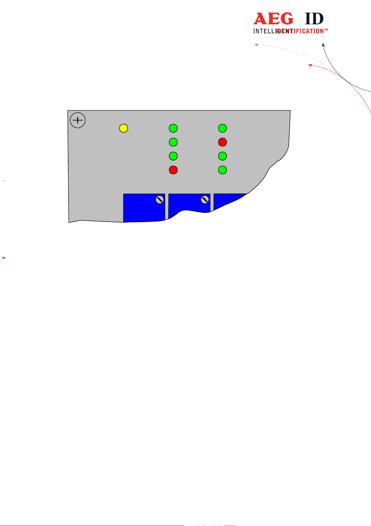
7.1 Indicators
The device has 9 indicators.
OP ANT
Figure 7-1: Position of all LED Indicators
Their function is:
OP: flashing as long as the microprocessor is working properly - life indication
ANT: on if antenna is operated
READ: on if last read was successful
NoRead: on if last read was not successful
ERR: on if a hardware error was detected, i.e. antenna is faulty or missing
Run: on, if slave is in the state data_exchange (Profibus Run)
BusFail: on, if slave is not in the state data_exchange (Profibus Fail)
RX: on as long as new information are received from the PLC (commands)
TX: on as long as new information is transmitted to the PLC (answers)
Run
READ
NoREAD
ERR Tx
BusFail
RX
8 Integration into the Profibus Network
If the device is running due to chapter 7 all to do is to integrate the slave into the PLC environment.
The steps are that one which are common when integration a Profibus slave:
• load GSD-file into the PLC
• Check existing Profibus network for unused slave adress. Adjust unused slave adress in the ARE
K1/PFB device (see chapter 6)
• Check position of termination switch of the ARE K1 /PFB device, only the device at the end of
the network line has to be terminted!
• Allocate the node adress in the PLC
--------------------------------------------------------------------------------14/18--------------------------------------------------------------------------------
Page 15

code
DIAG
diagn
osis / state of the reader
state or error message
GT read transponder (get tag)
transponder number
INIT
load basic configuration
boot message / <CR>
RST warm start
boot message / <CR>
VER Output version number
version number
VS Output of all parameter
val
ues List of parameters
VSAVE
store current configuration
ok
8.1 Profibus Slave: Configuration and Parametrization
The ARE K1 / PFB has one configuration only. Only the seven standard Profibus parameters are defined. So it is not necessary, to handle with device specific parameters (User_Prm_data).
If the device is parametrized successfully it is ready for data tranfer. The green LED indicator "Run" is
on.
Attention !
Inside of a network line, it’s not allowed to install more then 32 reader devices.
The red LED indicator "BusFail“ has to be off, otherwise an error has occured.
The information about the data tranfer protocoll is documented in a special manual [2] : Profibus-DP
Communication.
9 Modes of Operating and Commands of the Reader
Only one mode of operating is defined for the ARE K1 / PFB:
• mode 2 - reading triggered by the PLC
This mode is specified in the next subchapter briefly. Beyond that we refer you to the much more detailed description in [1] : Set of Commands for ARE K1.
9.1 Set of Commands
The reader supports the AEG ID Standardized Command Set (ASB). Due to the specific operating requirements in the deterministic Profibus process, the amount of commands and parameters of the
ARE K1 / PFB have been reduced as specified below.
Listing of commands available in the ARE K1 / PFB:
command-
function action on interface
Table 9-1: List of all reader commands
The ARE K1 / PFB reader has parameters, listed in Table 9.2 below. The parameters NRD and NID
should only be changed after consulting the manufacturer.
--------------------------------------------------------------------------------15/18--------------------------------------------------------------------------------
Page 16

code
ALGO
type of transponder
1, 2 1 (trovan read only)
cycle
NRD
superimposition of telegrams
0 .. 2
1 (two telegrams)
cess)
cess)
reading
command-
function valid para-
meter values
default-values
NID number of identical IDs per reading
QN1 digital output QN1 0 .. 2 2 (controlled by reading pro-
QR1 digital output QR1 0 .. 2 2 (controlled by reading pro-
TOR timeout parameter for unsuccessfull
Table 9.2: Parameters available for the ARE K1 / PFB
0 , 1 1 (two out of two)
0...255 5 (500ms)
9.2 Operating mode 2 - Reading Triggered by the PLC
The PLC sends the command "GT" to trigger a reading process. After finishing the reading process the
transponder code or an error code can be read by the PLC.
9.2.1 Principle of Reading a Transponder in mode 2
• Trigger the Reader device using the command "GT "(and <CR> in addition)
• Wait for answer of the reader device, polling status bit in response telegram (see manual [2] : Pro-
fibus-DP Communication)
• Request answer (see manual [2] : Profibus-DP Communication)
10 Warning Notes
• This reader is an active electrical transmission system and radiates in the frequency range of ap-
proximately 124 kHz. When connecting a defect or a not suited reader to the device the radiated
power can be higher than 42dBµA/m (measured at 10 m distance). The operator is responsible
that people at risk are not endangered by the device..
• Do not operate the device with open housing, as otherwise there is a danger, that positions with
dangerous voltage can be touched.
• Never operate the device with defect antenna cables. The antenna cables may conduct dangerous
voltages. When disconnecting an antenna cable please assure that the device is turned off and the
cable was grounded for a short time before touching it. Otherwise stored energy of the antenna
may cause harm.
• The reader box has to opened by well educated people only.
--------------------------------------------------------------------------------16/18--------------------------------------------------------------------------------
Page 17

Caution !
Never mount or place the antenna on extended metal parts.
Do not bring another antenna very near to the operated antenna (second antenna op-
erated or not). In both cases there is a risk, that the antenna may be destroyed. Such
defects are not covered by the warranty. An unusual high current consumption can be
a hint for such not allowed configuration
11 FCC Information
Federal Communications Commission (FCC) Statement
15.21
You are cautioned that changes or modifications not expressly approved by the part responsible for compliance could void the user’s authority to operate the equipment.
15.105(a)
This equipment has been tested and found to comply with the limits for a Class A digital device, pursuant to Part 15 of the FCC Rules. These limits are designed to provide reasonable
protection against harmful interference when the equipment is operated in a commercial environment. This equipment generates, uses, and can radiate radio frequency energy and, if
not installed and used in accordance with the instruction manual, may cause harmful interference to radio communications. Operation of this equipment in a residential area is likely
to cause harmful interference in which case the user will be required to correct the interference at his own expense.
--------------------------------------------------------------------------------17/18--------------------------------------------------------------------------------
Page 18

12 Documentation, References
[1]: Manual: Set of Commands for ARE K1
Specifies all commands, parameters, transfer protocol, error codes and control characters
used in the ARE K1.
[2]: Manual: Profibus-DP Communication
Specifies the data transfer telegram used between PLC and Profibus-slave.
13 Contacts
To improve our products, as well as its documentation is our permanent effort.
For any questions, feedback or comments please call:
Fax: ++49 (0)731-140088-0
Fax: ++49 (0)731-140088-9000
e-mail: sales@aegid.de
http:\
www.aegid.de
14 notification of changes
change no date description of change version editor
18.05.16
22.06.16
27.07.16
• First release
• FCC Information
• FCC Information correction
• FCC Information correction
01
02 MK
03 MK
04 MK
--------------------------------------------------------------------------------18/18--------------------------------------------------------------------------------
 Loading...