

Page 1
TM 43600 / TM 63600
Teppan Yaki Grill plate
Installation and Operating Instructions
Page 2

Dear Customer,
Please read these user instructions carefully and keep them to refer to
later.
Please pass the user instructions on to any future owner of the appliance.
The following symbols are used in the text:
1 Safety instructions
Warning! Information that affects your personal safety.
Important! Information that prevents damage to the appliance.
3 Useful tips and hints
2 Environmental information
2
Page 3

Contents
OPERATING INSTRUCTIONS . . . . . . . . . . . . . . . . . . . . . . . . . . . . . . . 4
Safety . . . . . . . . . . . . . . . . . . . . . . . . . . . . . . . . . . . . . . . . . . . . . . . . . . . . . . . . . 4
Disposal . . . . . . . . . . . . . . . . . . . . . . . . . . . . . . . . . . . . . . . . . . . . . . . . . . . . . . . 5
Description of appliance. . . . . . . . . . . . . . . . . . . . . . . . . . . . . . . . . . . . . . . . . 6
Key features of your appliance. . . . . . . . . . . . . . . . . . . . . . . . . . . . . . . . . . . . . 6
TM 63600 unit construction. . . . . . . . . . . . . . . . . . . . . . . . . . . . . . . . . . . . . . . 7
TM 43600 unit construction. . . . . . . . . . . . . . . . . . . . . . . . . . . . . . . . . . . . . . . 7
Special accessories . . . . . . . . . . . . . . . . . . . . . . . . . . . . . . . . . . . . . . . . . . . . . . . 8
Before using for the first time . . . . . . . . . . . . . . . . . . . . . . . . . . . . . . . . . . . 8
Initial cleaning . . . . . . . . . . . . . . . . . . . . . . . . . . . . . . . . . . . . . . . . . . . . . . . . . . 8
Using the grill plate. . . . . . . . . . . . . . . . . . . . . . . . . . . . . . . . . . . . . . . . . . . . . 9
Thermostat . . . . . . . . . . . . . . . . . . . . . . . . . . . . . . . . . . . . . . . . . . . . . . . . . . . . . 9
Switching on and off. . . . . . . . . . . . . . . . . . . . . . . . . . . . . . . . . . . . . . . . . . . . . 9
Application, tables, tips . . . . . . . . . . . . . . . . . . . . . . . . . . . . . . . . . . . . . . . . . 10
Fat temperatures . . . . . . . . . . . . . . . . . . . . . . . . . . . . . . . . . . . . . . . . . . . . . . . . 10
Tables. . . . . . . . . . . . . . . . . . . . . . . . . . . . . . . . . . . . . . . . . . . . . . . . . . . . . . . . . . 11
Cleaning and care . . . . . . . . . . . . . . . . . . . . . . . . . . . . . . . . . . . . . . . . . . . . . . 13
Final cleaning of grill plate . . . . . . . . . . . . . . . . . . . . . . . . . . . . . . . . . . . . . 13
Cleaning the grill plate between two courses. . . . . . . . . . . . . . . . . . . . . . 13
Cleaning control panel. . . . . . . . . . . . . . . . . . . . . . . . . . . . . . . . . . . . . . . . . 13
Cleaning cooking cover . . . . . . . . . . . . . . . . . . . . . . . . . . . . . . . . . . . . . . . . 13
SERVICE . . . . . . . . . . . . . . . . . . . . . . . . . . . . . . . . . . . . . . . . . . . . . . . . . . . . . 14
INSTALLATION INSTRUCTIONS. . . . . . . . . . . . . . . . . . . . . . . . . . . . 15
Technical data . . . . . . . . . . . . . . . . . . . . . . . . . . . . . . . . . . . . . . . . . . . . . . . . . . 15
TM 63600 . . . . . . . . . . . . . . . . . . . . . . . . . . . . . . . . . . . . . . . . . . . . . . . . . . . 15
TM 43600 . . . . . . . . . . . . . . . . . . . . . . . . . . . . . . . . . . . . . . . . . . . . . . . . . . . 15
Regulations, standards, guidelines . . . . . . . . . . . . . . . . . . . . . . . . . . . . . . . . . . 15
Safety instructions for the installer. . . . . . . . . . . . . . . . . . . . . . . . . . . . . . . . . 16
Electrical connection. . . . . . . . . . . . . . . . . . . . . . . . . . . . . . . . . . . . . . . . . . . . . 16
Rating plates . . . . . . . . . . . . . . . . . . . . . . . . . . . . . . . . . . . . . . . . . . . . . . . . . . . 17
Fitting/installation in working surface: surface mounting
(coated, lined, Inox or stone) . . . . . . . . . . . . . . . . . . . . . . . . . . . . . . . . . . . . . . 18
Fitting/installation: flush mounting in stone working surfaces . . . . . . . . . . 22
3
Page 4

OPERATING INSTRUCTIONS
1 Safety
The safety of this appliance complies with accepted technical standards
and the Appliance Safety Law. As manufacturers, however, we also be
lieve it is our responsibility to familiarise you with the following safety
instructions.
Electrical safety
• The installation and connection of the new appliance must only be
carried out by qualified personnel.
• Repairs to the appliance must only be carried out by approved service
engineers. Repairs carried out by unqualified persons may cause inju
ry or serious malfunction. If your appliance needs repairing, please
contact your local customer centre or your dealer.
3 Please follow these instructions, otherwise the warranty is void in the
event of damage.
• Flush-mounted appliances may only be operated following installation in suitable installation cabinets and working surfaces which conform with the relevant standards. This ensures sufficient protection
against contact for electrical units as required by the safety provisi
ons.
• If your appliance malfunctions or if fractures, cracks or splits appear:
– switch off all heating zones,
– disconnect or remove the fuse for the grill plate.
-
-
-
Child safety
• The heating zones become hot when you cook and grill. Therefore, always keep young children away from the appliance. This also applies
after switching off until the temperature of the grill plate has cooled
sufficiently.
Safety during use
• This appliance may only be used for normal cooking, frying and grilling of food in the home.
• Do not use the grill to heat the room.
• Take care when plugging electric appliances into mains sockets near
the unit. Connecting leads must not come into contact with the hot
grill plate.
4
Page 5

• Overheated fat and oil catch fire quickly. If food is flambéed, the
cooking process should be supervised.
• Switch off the grill plate every time after use.
Special information for the grill plate
Do not place any objects which can be magnetised on the grill plate
while in operation.
3 Noises may occur during operation by expansion of the grill plate. The-
se are not faults in the unit and the function is not impaired in any
way.
Safety when cleaning
• The unit must be switched off and cooled below 90 °C before cleaning.
• For safety reasons it is not permitted to clean the unit with a steam
jet or high-pressure cleaner.
How to avoid damage to the appliance
• Do not use cast iron pans or pans with a rough, burred or damaged
base. Scratching may occur if the pans are slid across the surface.
• Keep all items and materials that can melt away from the grill plate,
e.g. plastics, aluminium foil or oven foils. If something of this nature
should melt onto the grill plate, it must be removed immediately with
a metal spatula.
Disposal
2 Packaging material
The packaging materials are environmentally friendly and can be recycled. The plastic components are identified by markings, e.g. >PE<, >PS<,
etc. Please dispose of the packaging materials in the appropriate con
tainer at the community waste disposal facilities.
2 Old appliance
The symbol W on the product or on its packaging indicates that this
product may not be treated as household waste. Instead it shall be han
ded over to the applicable collection point for the recycling of electrical and electronic equipment. By ensuring this product is disposed of
correctly, you will help prevent potential negative consequences for the
-
-
5
Page 6

environment and human health, which could otherwise be caused by
inappropriate waste handling of this product. For more detailed infor
mation about recycling of this product, please contact your local city
office, your household waste disposal service or the shop where you
purchased the product.
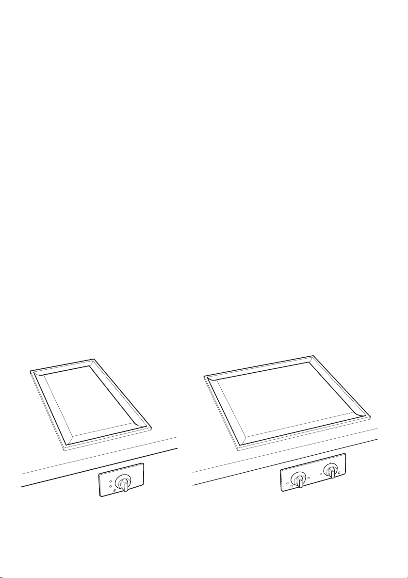
Description of appliance
Key features of your appliance
• The highly conducting grill plate is 10 mm thick. It consists of twinlayer stainless steel and therefore has a good thermal capacity. This
prevents a rapid decrease in temperature, e.g. when preparing meat
from the refrigerator.
• The channeld edge fulfils three important functions:
– It reduces the temperature at the installation surfaces so much that
the grill plate can be fitted in various kitchen working surfaces.
– The curvature of the channel absorbs the expansion of the heated
grill plate to keep it flat.
– Minor food remnants and liquids can easily be fed to the channel
and removed.
• The thermostat with readable temperature setting ensures a constant
temperature. This prevents overheating of the food and permits lowfat cooking with retention of nutritional value.
• The food is prepared (heated) directly on the grill plate with or without fat. It is also possible, however, to cook with pots.
• The heating time, e.g. to 180 °C, is approx. 6–7 minutes.
The cooling time, e.g. from 180 °C to 100 °C, is approx. 45 minutes, or
°C approx. 60 minutes.
to 60
-
6
Page 7
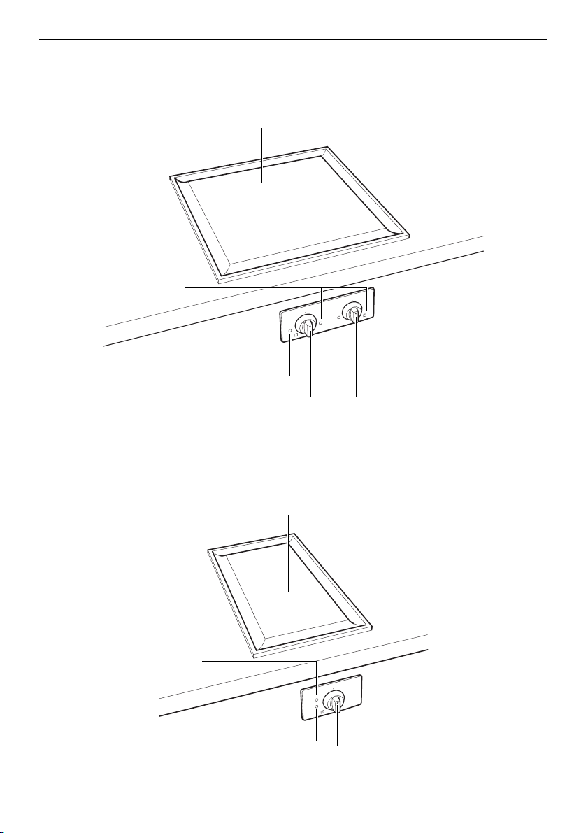
TM 63600 unit construction
Grill plate with two heating zones
(front half and rear half)
Temperature
indication lamps (yellow)
Operating indication
lamp (red)
Thermostat for front
heating zone (with symbol)
TM 43600 unit construction
Thermostat for rear
heating zone (with symbol)
Operating indication
lamp (red)
Temperature
indication lamp (yellow)
Grill plate with one heating zone
Thermostat
7
Page 8

Special accessories
Stainless steel cooking
cover (255 x 140)
The cooking cover is specially suitable
for steaming vegetables, for keeping
cooked food warm or heating it up,
e.g. rice, noodles.
If roasting is performed under the
cover, everything is kept nice and
fresh. Annoying evaporation or splas
hing is largely avoided.
-
Before using for the first time
Initial cleaning
Wipe over the control panel with a damp synthetic fibre cloth.
1 Important: Do not use any caustic, abrasive cleaning agent, which
could damage the surface.
Wipe over the grill plate when cold with a damp cloth or for example
with a scouring sponge for delicate surfaces in the grinding direction.
Finish cleaning thoroughly with a damp cloth.
8
Page 9
Using the grill plate
The food is prepared (heated) directly on the grill plate with or without
fat. It is also possible, however, to cook with pots.
When using pots on the grill plate, however, the cooking time is considerably longer than on glass-ceramic, gas rings or cast iron plates.
Garnishings accompanying the menu, e.g. sauces, rice, etc. can be
cooked or kept warm very well in the pan directly on the grill plate.
It is not recommended to cook large amounts on the grill plate, e.g.
spaghetti.
3 Do not hesitate to turn over or remove the food with a spoon while
cooking on the grill plate. Working marks on the grill plate are normal
and do not result in impairment of function.
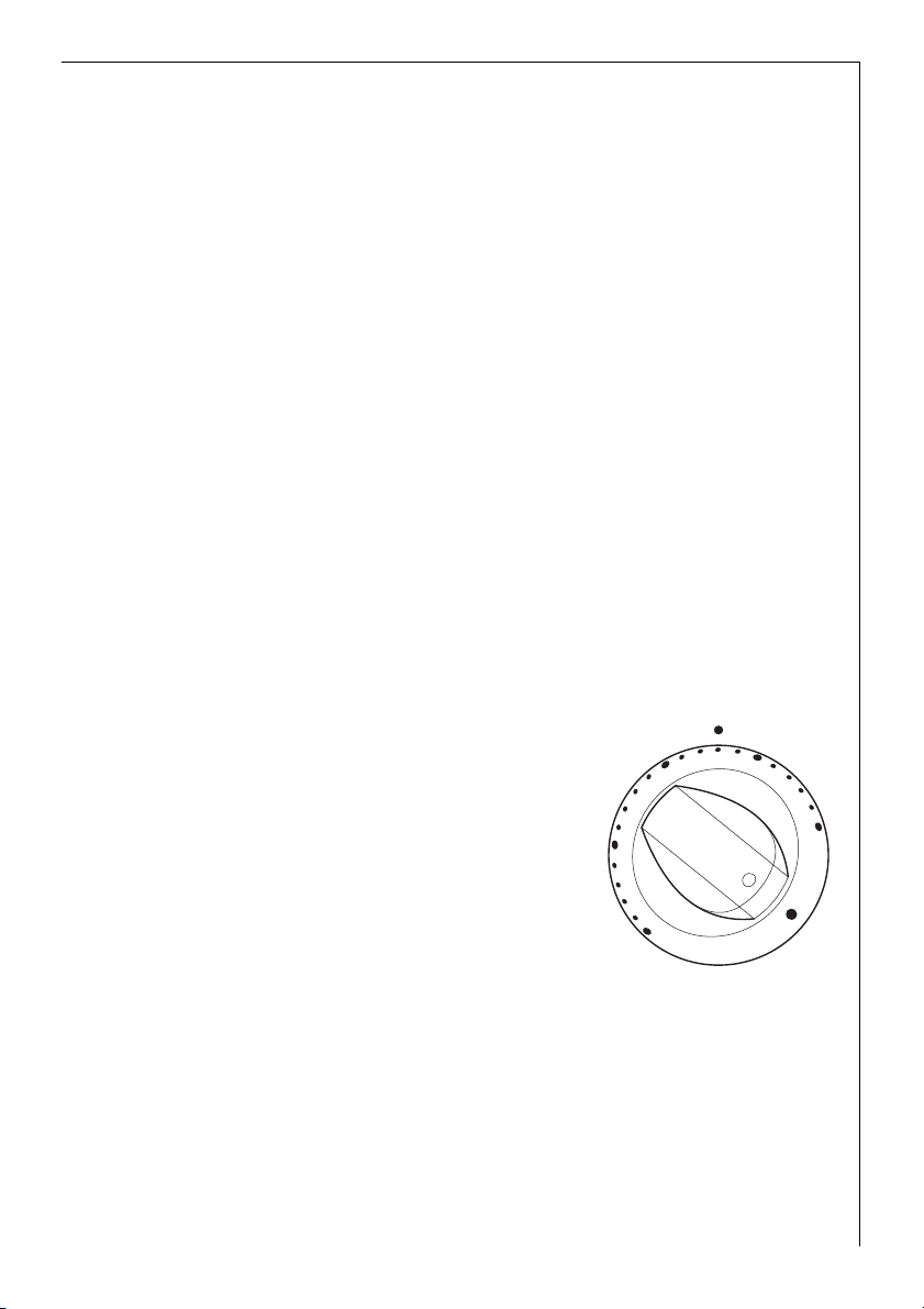
Thermostat
The required temperature of the grill plate can be set fully variably
within the range 50
°C and 250 °C.
3 The heating time, e.g. to 180 °C, is approx. 6–7 minutes.
Switching on and off
1. Turn the thermostat clockwise to the
required temperature.
– The red operating indication lamp
lights.
– The yellow temperature indication
lamp lights while the unit is hea
ting up.
2. When the temperature indication
lamp extinguishes, the temperature
set is reached.
– The temperature is kept constant
by the thermostat.
– The temperature indication lamp
lights again during further heating.
150
-
200
100
250
50
9
Page 10
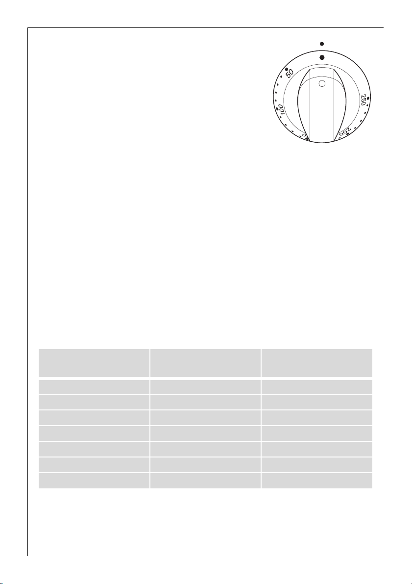
3. To switch off turn back to the off position.
3 If more rapid cooling of the grill plate
is desired after switching off, this can
be performed by placing a pot on it
with a large base and containing
2–3 litres cold water.
Application, tables, tips
Fat temperatures
If fats and oils are used the correct temperature is of vital importance.
Heating should not be too great for health reasons, since this could
produce substances injurious to health, e.g. acryl amine.
With the correct temperature setting the valuable constituents of the
oils and fats are largely retained.
The fat temperature is the maximum temperature which can be reached before the fat or oil begins to smoke.
If the smoke point is exceeded, the fats and oils burn, are modified and
become useless; the smoke point should not be exceeded.
10
Fats/oils
Butter 130 °C 150 °C
Pork fat 170 °C 200 °C
Beef fat 180 °C 210 °C
Olive oil 180 °C 200 °C
Sunflower oil 200 °C 220 °C
Peanut oil 200 °C 235 °C
Coconut fat 220 °C 240 °C
Fat temperature
(max. temperature)
Smoke point
Page 11

Tables
Cooking material
Fish and crustaceans 170–180 Preheat grill plate
Salmon cutlets 170 8 mins., turn after 4 mins.
Giant prawns (without shell) 170 6 mins., turn after 3 mins.
Shark steaks, 2.5 cm thick 180 10 mins., turn after 5 mins.
Sole (in butter) 180 8 mins., turn after 4 mins., light side first
Fillets of plaice 180 6 mins., turn after 3 mins.
Veal 170-190 Preheat grill plate
Veal cutlet 180 10 mins., turn after 5 mins.
Veal medallions, 4 cm thick 180 10 mins., turn after 5 mins.
Veal steaks, 3–4 cm thick 180 6 mins., turn after 3 mins.
Escalope of veal, plain 180 5 mins., turn after 2½ mins.
Chopped veal 180 6 mins., turn after 3 mins.
Beef 200–220 Preheat grill plate
Beef steak very rare
rare
medium
well done
Hamburger 200 6–8 mins., turn after 3–4 mins.
Châteaubriand 200
Pork 180–220 Preheat grill plate
Pork medallions 180 8 mins., turn after 4 mins.
Neck steak 200 8 mins., turn after 4 mins.
Escalope 200 6 mins., turn after 3 mins.
Spare ribs 180 8–10 mins., turn several times
Pork kebab 200 6–8 mins., grill well from all sides
Temperature
(°C)
220
220
220
220
100
Time/tips
(the strips of meat should not touch)
2 mins., turn after 1 min.
4 mins., turn after 2 mins.
6 mins., turn after 3 mins.
8 mins., turn after 4 mins.
without fat the times are increased
by around 20 %
Roast meat in oil fully on all sides
(only turn when the meat detaches)
10 Min. finish cooking on one side
(according to thickness)
11
Page 12

Cooking material
Lamb 180–200 Preheat grill plate
Lamb chop 180 10 mins., turn after 5 mins.
Lamb fillet 180 10 mins., turn after 5 mins.
Lamb steak 200 6–8 mins., turn after 3–4 mins.
Poultry 160–180 Preheat grill plate
Chicken breast fillet 180 8–10 mins., turn after 4–5 mins.
Turkey breast strips 170 6 mins., turn several times
Bratwurst (pork sausage) 200 Preheat grill plate
Temperature
(°C)
Time/tips
(it is important to grill the fillets all round)
12
Page 13

Cleaning and care
Final cleaning of grill plate
1 Warning: Danger of injury from burns when cleaning the hot grill
plate!
1 Important: Always clean the grill plate in the grinding direction (not
with circular motions)! Never use abrasive powders or aggressive clea
ning agents!
1. Switch off unit and allow to cool to approx. 100 °C.
3 If the grill plate has already cooled before cleaning, heat to approx.
°C and switch off again.
100
2. Place ice cubes on the grill plate and simultaneously detach dirt with a
turning spoon and push into the channel until all the major remnants
have been removed. Remove these from the channel (e.g. with kitchen
paper). Warning: Hot!
3 Cold water can also be used instead of ice cubes.
3. Allow grill plate to cool to approx. 100 °C. Clean thoroughly with with a
scouring sponge for delicate surfaces and a little cold water in the grin
ding direction.
4. Remove spots which could originate from egg white or acids in foods
when cold with a little lemon juice and clean with a scouring sponge
for delicate surfaces. Finish cleaning thoroughly with a damp cloth.
-
-
Cleaning the grill plate between two courses
Similar to point 2–3 „Final cleaning of grill plate".
Cleaning control panel
Wipe over the control panel with a damp synthetic fibre cloth.
1 Important: Do not use a caustic, abrasive cleaning agent, which could
damage the surface.
Cleaning cooking cover
The cooking cover can be cleaned in the dishwasher.
13
Page 14

SERVICE
In the event of technical faults, please first check whether you can
remedy the problem yourself with the help of the operating instruc
tions.
If you were not able to remedy the problem yourself, please contact the
Customer Care Department or one of our service partners.
In order to be able to assist you quickly, we require the following
information:
– Model description
– Product number (PNC)
– Serial number (S No.) (for numbers see rating plate)
– Type of fault
So that you have the necessary reference numbers from your appliance
at hand, we recommend that you write them in here:
Model description: .....................................
PNC: .....................................
S No: .....................................
-
14
Page 15

INSTALLATION INSTRUCTIONS
Warning! Installation and connection of the new appliance must only
1
be performed by a certified expert.
Please pay attention to these instructions, since otherwise the warranty
becomes invalid if any damage occurs.
Technical data
TM 63600
Power consumption
• Grill heater front 1500 W
• Grill heater rear 1500 W
Heater voltage 230 V ~ 50 Hz
Total consumption 3,0 kW
Power supply 230 V
TM 43600
Power consumption 2200 W
Heater voltage 230 V ~ 50 Hz
Total consumption 2,2 kW
Power supply 230 V
Regulations, standards, guidelines
This appliance satisfies the following standards:
• EN 60 335-1 and EN 60 335-2-6
governing the safety of electrical appliances for household use and
• EN 60 350
governing basic protection requirements for electro-magnetic compatibility (EMC).
• EN 55014-2
• EN 55014-1999-10
• EN 61000-3-2
• EN 61000-3-3
governing basic protection requirements for electro-magnetic compatibility (EMC).
15
Page 16

5 This appliance complies with the following EU directives
• 93/68/EWG CE designation directive
• 73/23/EWG dated 19.02.1973 (low voltage directive)
• 89/336/EWG dated 03./05.1989 (EMC directive including modificati-
on directive 92/31/EWG)
Safety instructions for the installer
• The laws, ordinances, directives and standards in force in the country
of use are to be followed (safety regulations, proper recycling in ac
cordance with the regulations, etc.).
• This appliance corresponds to the type EN 60 335-2-6 with respect to
protection against fire. Only units of this kind may be fitted one-si
ded to adjoining high-level cabinets or walls.
• When fitted in combustible material, the local fire-protection regula-
tions must be observed without fail.
• Limit to room width 550 mm, height 127 mm from lower side of grill
plate, depth 560
mm. Combustible walls and ceilings must be provided with a fla-
600
me-retardant lining above the grill plate in conformity with the official fire regulations for the relevant area.
• Protection against contact must be ensured by the installation.
mm from rear with a working surface depth of
-
-
Electrical connection
• Electrical connection must be made by a certified installer.
• The mains connection to the built-in switchbox must be made with
the existing connecting cable and corresponding to the connection
diagram.
• A device must be provided in the electrical installation which allows
the appliance to be disconnected from the mains at all poles with a
contact opening width of at least 3
clude line protecting cut-outs, fuses (screw type fuses are to be removed from the holder), earth leakage trips and contactors.
• Warning! While being serviced the appliance must be disconnected
from the power supply. The rating plate is fitted on the underside of
the built-in switchbox.
16
mm. Suitable isolation devices in-
Page 17

• Before putting into operation detach any protective foil from the grill
plate.
• After connecting to the power supply all grill plates should be swit-
ched on briefly (approx. 2 minutes) in succession at the 100 °C position to check their readiness for operation.
Rating plates
Versions with two thermostats
Model Code
TM 63600
PNC 949 480 194
Versions with one thermostat
Model Code
TM 43600
PNC 949 480 193
17
Page 18

Fitting/installation in working surface: surface mounting (coated, lined, Inox or stone)
When fitting in combustible material, the laws, ordinances, directives
and standards in force in the country of use
protection regulations
1. The lateral spacing of the working surface cut-out from a high-level
cabinet and the rear wall must be at least 50
2. Cut out working surface according to specified cut-out dimensions. The
tolerances must be observed. Seal the cut-out area of the working sur
face against moisture with suitable varnish.
3. Holes for the built-in switchbox in the front of the cabinet with template as illustrated.
Panel thickness min. 16 mm, max. 22 mm.
4. Guide the built-in switchbox with the bundle of connecting conductors
from above through the working surfaces cut-out and from the rear to
the front of the cabinet.
Important: There are capillary tubes in the bunch of conductors between the built-in switchbox and the grill plate. Do not bend sharply or
separate or the appliance will be destroyed!
5a. Assembly with CN-front panel (CN)
Guide the signal lamps from the rear through the 12 mm dia. holes in
the front of the cabinet (the 12
mm to simplify assembly). Take the switch spindle(s) of the built-in
15
switchbox from the rear through the 13
signal lamps in the signal lamp lenses mounted on the CN front panel
from the rear.
– TM 63600: insert signal lamp with red wires in the left-hand red lens.
– TM 43600: insert signal lamp with red wires in upper red lens.
Screw CN-front panel with screws to front of cabinet under switch knobs. Attach switch knobes and then secure built-in switchbox in front
of cabinet from rear
5b.Assembly without CN-front panel (Vi)
Insert the signal lamp lenses supplied from the front in the 12 mm dia.
holes of the front of the cabinet.
– TM 63600: left-hand red lens.
– TM 43600: upper red lens.
Insert the signal lamps from the rear through the front of the cabinet
in the signal lamp lenses.
– TM 63600: insert signal lamp with red wires in the left-hand red lens.
– TM 43600: insert signal lamp with red wires in upper red lens.
are to be followed.
mm dia. holes can be enlarged to
as well as the local fire-
mm.
-
mm dia. hole(s) and insert the
18
Page 19

Take the switch spindle(s) of the built-in switchbox from the rear through the 13 mm dia. hole(s), attach white or black switch knobs as required and then secure the built-in switchbox from the rear to the
front of the cabinet.
6. For tiled working surfaces the joints must be completely filled with
jointing material in the supporting zone for the grill plate.
7. The enclosed sealing tape must be attached to the underside of the grill
plate.
8. Clean the working surface thoroughly in the seal supporting zone.
9. Place grill plate in cut-out from above, centre and press down firmly. It
requires no additional fixing owing to its own heavy weight.
Please do not apply any additional silicone sealing compound, since in
the event of removal of the grill plate both the seal and the working
surface could be damaged.
Important: If not fitted correctly it would be difficult to remove for
servicing and the grill plate and working surface could be damaged.
Warning: A recess base which can be dismantled must be fitted as contact protection under the grill plate/built-in switchbox.
Removing the grill plate
1. Remove power supply from built-in switchbox/grill plate.
2. Place a clean spatula as protection on the working surface. Then care-
fully run a firmer chisel under the edge of the grill plate and raise.
3. For a new fitting it must be ensured that the old seal is removed completely cleanly and a new seal fitted (available from spare-parts sales).
Removing the built-in switchbox (for servicing)
1. Remove power supply from built-in switchbox and dismantle the recess
base.
2. Pull off switch knobs (if present remove CN front panel forwards).
Withdraw signal lamps from the lenses from the rear, release fixing
screws of built-in switchbox on the front of the cabinet from the rear,
draw the switchbox forwards carefully through the opening in the
recess base. Re-fitting is performed according to the fitting/installation
text.
Important: There are capillary tubes in the bunch of conductors between the built-in switchbox and the grill plate. Do not bend sharply or
separate or the appliance will be destroyed.
19
Page 20

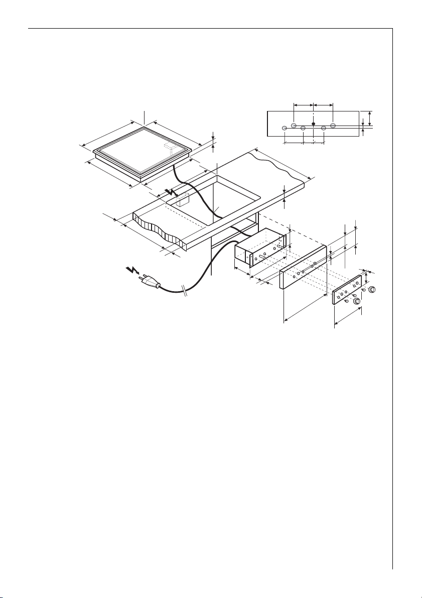
Surface mounting TM 43600
Grill plate with built-in switchbox
Width of fume exhaust hood 550 mm min.
R7
380
488
510
358
55
R5
360
==
ø12
ø13
ø12
45
600
12,5
12,5
25
min. 75
55
Connection to
socket provided
by client
490 1
+
–
1,8 m
230 V (10 A)
55
0,75 m
130
195
16-22
min. 25
75
min.75
x
3
70
x
160
20
Page 21
Surface mounting TM 63600
Grill plate with built-in switchbox
Width of fume exhaust hood 550 mm min.
580
488
55
490 1
Connection to socket
provided by client
R7
558
+
–
55
1,8 m
230 V (16 A)
510
560
R5
0,75 m
55
130
315
16-22
ø12 ø12 ø12
ø13 ø13
8080 45 45
600
min. 25
85 85
85
x
10
min. 75
280
min. 75
10
x
3
70
21
Page 22

Fitting/installation: flush mounting in stone working surfaces
When fitting in combustible material, the laws, ordinances, directives
and standards in force in the country of use
protection regulations
1. The lateral spacing of the working surface cut-out from a high-level
cabinet and the rear wall must be at least 50
2. Cut out working surface according to specified cut-out dimensions. The
tolerances must be observed.
3. Holes for the built-in switchbox in the front of the cabinet with template as illustrated.
Panel thickness min. 16 mm, max. 22 mm.
4. Guide the built-in switchbox with the bundle of connecting conductors
from above through the working surfaces cut-out and from the rear to
the front of the cabinet.
Important: There are capillary tubes in the bunch of conductors between the built-in switchbox and the grill plate. Do not bend sharply or
separate or the appliance will be destroyed!
5a. Assembly with CN-front panel (CN)
Guide the signal lamps from the rear through the 12 mm dia. holes in
the front of the cabinet (the 12
mm to simplify assembly). Take the switch spindle(s) of the built-in
15
switchbox from the rear through the 13
signal lamps in the signal lamp lenses mounted on the CN front panel
from the rear.
– TM 63600: insert signal lamp with red wires in the left-hand red lens.
– TM 43600: insert signal lamp with red wires in upper red lens.
Screw CN-front panel with screws to front of cabinet under switch knobs. Attach switch knobes and then secure built-in switchbox in front
of cabinet from rear
5b.Assembly without CN-front panel (Vi)
Insert the signal lamp lenses supplied from the front in the 12 mm dia.
holes of the front of the cabinet.
– TM 63600: left-hand red lens.
– TM 43600: upper red lens.
Insert the signal lamps from the rear through the front of the cabinet
in the signal lamp lenses.
– TM 63600: insert signal lamp with red wires in the left-hand red lens.
– TM 43600: insert signal lamp with red wires in upper red lens.
Take the switch spindle(s) of the built-in switchbox from the rear through the 13 mm dia. hole(s), attach white or black switch knobs as re-
are to be followed.
mm dia. holes can be enlarged to
as well as the local fire-
mm.
mm dia. hole(s) and insert the
22
Page 23

quired and then secure the built-in switchbox from the rear to the
front of the cabinet.
6. Clean the working surface thoroughly in the cut-out and in the rebate.
7. The enclosed rubber tape (3x10x2400 mm) must be attached to the
cut-out supporting surface (to soften blows and prevent silicone joint
sealing compound running under the grill plate under all circumstances
when pointing).
Important: If not fitted correctly, removal would be made more difficult for servicing. The grill plate and working surface could be damaged
in this way.
8. Place grill plate carefully in cut-out and align so that the joint is the
same size on all sides. The grill plate is not fastened!
Warning: A recess base which can be dismantled must be fitted as contact protection under the grill plate/built-in switchbox.
9. Clean grill plate and working surface in area of joint (e.g. with isopropyl
alcohol and fluff-free cloth) and fill the joint with a heat-resistant (at
least 160
°C) silicone joint sealing compound.
Note: Since the grill plate and working surface cut-out are subject to a
certain dimensional tolerance, the width of the joint can vary (min.
mm).
2
Removing the grill plate
1. Remove power supply from built-in switchbox/grill plate.
2. Cut open the silicone joint sealing compound provided by the client
with a suitable knife along the edge of the grill plate to the full depth
of the joint. Raise the grill plate carefully from below to the lower
construction shell with a screwdriver.
3. For a new fitting it must be ensured that the old silicone compound
and the rubber tape are cleanly removed completely and a new rubber
tape fitted for softening blows (available from spare-parts sales,
3x10x2400 mm).
lation text
.
Re-fitting is performed according to the fitting/instal-
23
Page 24

Removing the built-in switchbox (for servicing)
1. Remove power supply from built-in switchbox and dismantle the recess
base.
2. Pull off switch knobs (if present remove CN front panel forwards).
Withdraw signal lamps from the lenses from the rear, release fixing
screws of built-in switchbox on the front of the cabinet from the rear,
draw the switchbox forwards carefully through the opening in the
recess base. Re-fitting is performed according to the fitting/installation
text.
Important: There are capillary tubes in the bunch of conductors between the built-in switchbox and the grill plate. Do not bend sharply or
separate or the appliance will be destroyed!
Flush mounting TM 43600
Grill plate with built-in switchbox
Width of fume exhaust hood 550 mm min.
R10
min. 7
490
R5
380
488
R7
358
510
386
360
60
360
13
==
ø12
ø13
ø12
600
45
12,5
12,5
25
min. 75
Connection to
socket provided
by client
24
0,75 m
=
490 1
516
1,8 m
230 V (10 A)
+
–
=
130
195
16-22
min. 25
75
min.75
x
3
70
x
160
Page 25

Flush mounting TM 63600
Grill plate with built-in switchbox
Width of fume exhaust hood 550 mm min.
R10
488
580
R7
510
558
586
560
490
60
R5
560
13
600
min. 7
85 85
ø12 ø12 ø12
ø13 ø13
8080 45 45
min. 75
10
=
Connection to
socket provided
by client
490 1
516
1,8 m
230 V (16 A)
0,75 m
+
–
=
130
315
16-22
min. 25
85
x
10
3
min. 75
70
x
280
25
Page 26

26
Page 27

27
Page 28

From the Electrolux Group. The world´s No.1 choice.
The Electrolux Group is the world´s largest producer of powered appliances for kitchen, cleaning and outdoor
use. More than 55 million Electrolux Group products (such as refrigerators, cookers, washing machines,
vacuum cleaners, chain saws and lawn mowers) are sold each year to a value of approx. USD 14 billion in more
than 150 countries around the world.
374 404 303-B-140405-03
Subject to change without notice
 Loading...