

Page 1
INSTALL ATION AND
MAINTENANCE
OF
WA SL3 M
TK SL3 M
TA SL3 M
WASHING MACHINE 2-15
TUMBLE DRYER 16-34
INDEX 36
Page 2

CONTENTS – WASHING MACHINE
SAFETY 3
Transit screws
General
Child lock on Start/Stop button
Door
Overfill cut-out
Packaging
Transport/Winter storage
Scrapping
PARTS OF THE WASHING MACHINE 4
TECHNICAL INFORMATION 4–5
Technical data
Programme cycles
MECHANICAL INSTALLATION 6–8
Transit screws
Positioning the washing machine
Adjusting the feet
Connecting to water supply
Water intake – mixed or cold water
Connecting to drain
CHANGING SETTINGS 10–11
Language
Locking the programme
Wash temperature, C or F
Changing preset wash temperature
Child lock
MAINTENANCE 12–13
Emptying/cleaning trap and drain pump
Inspection holes under drum paddles
Cleaning the detergent drawer
Cleaning the outside of the machine
In areas with hard water
TROUBLESHOOTING 14–15
Door will not open
Machine will not start
Error messages
The display is lighting when a program
me is selected, but no characters or
digits are shown
Wrong language displayed
ELECTRICAL INSTALLATION 9
Electrical installation
Connecting to coin mechanism
WASHING MACHINE CONTENTS
2
Page 3

SAFETY
GENERAL
• Read and keep this manual!
• Any electrical work or plumbing must be car-
ried out by qualified tradesmen.
• Remove the transit screws before you use the
machine, see Mechanical installation.
CHILD LOCK ON BUTTON
To prevent accidental button pushes on the
button you can activate the child lock
function. The
button then must be held
in for three seconds to activate the machine.
DOOR
The door is opened electrically, so it cannot be
opened until the machine is connected to the
electrical supply! The door can however be ope-
ned in an emergency, see Troubleshooting.
OVERFILL CUT-OUT
If the water level in the machine rises above
normal the overfill cut-out shuts off the water
intake and starts pumping out the water. The
programme resumes when the water level has
dropped.
TRANSPORT/WINTER STORAGE
If you intend to transport the machine or store
it over winter in unheated premises, empty the
trap and the drain pump, see the chapter on
Maintenance.
Any questions? Call service.
SCRAPPING
At the end of its life the machine must be disa-
bled before being scrapped.
Contact your local recycling centre to find
out where to dispose of it or recycle it.
The machine has been built and marked to
facilitate recycling.
PACKAGING
Recycle the packaging according to recommen-
dations in your area.
SAFETY WASHING MACHINE
3
Page 4
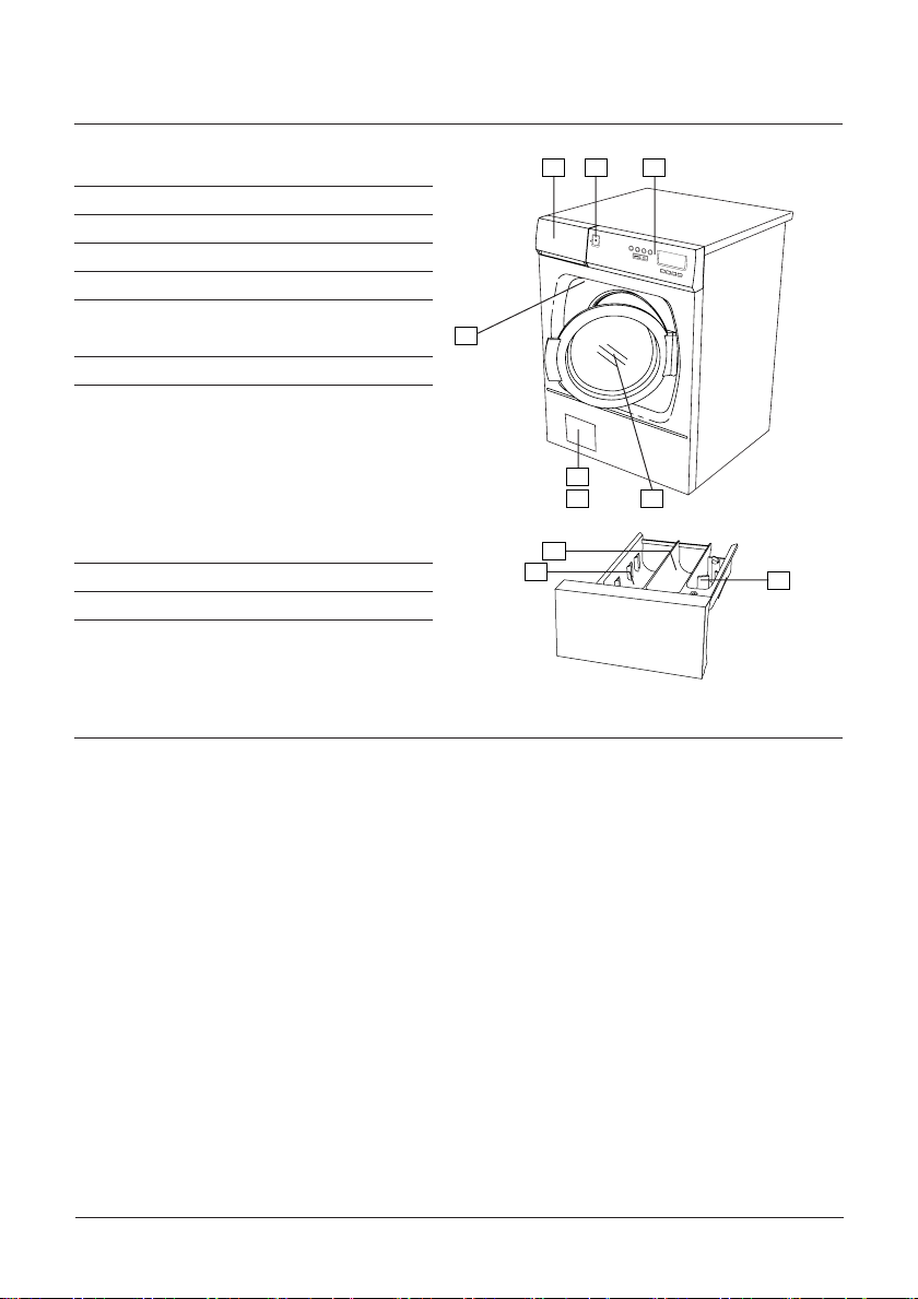
PARTS OF THE WASHING MACHINE
1
7
6
5
8
2
4
3
1. DETERGENT DRAWER
2. POWER SWITCH
3. PROGRAMME PANEL
4. RATING PLATE
5. DOOR-DRAIN PUMP/EMERGENCY OPEN
6. DRAIN PUMP/EMERGENCY OPEN (BEHIND
FLAP)
7. DOOR
1. DETERGENT COMPARTMENT – PRE-WASH
2. DETERGENT COMPARTMENT – MAIN WASH
3. FABRIC CONDITIONER COMPARTMENT
4
1 2 3
5
6
1
2
7
TECHNICAL INFORMATION
TECHNICAL DATA
Height, Width, Depth: 850 mm, 595 mm, 585 mm.
Weight: 73 kg.
Drum capacity: 50 l.
Max wash load: 6.0 kg.
Spin speed: 1200 rpm.
Power rating and element power: See rating plate.
Water pressure: 0.1–1 MPa, 1–10 kp/cm2, 10–100 N/cm2.
Composition of drum and fluid container: Stainless steel.
Composition of casing: Powder-painted and hot-dip galvanized sheet steel
or stainless steel.
Installation: Static on four adjustable, rubber-covered feet.
Water supply: 1.5 m PEX hose.
Drain: 1.7 m polypropylene hose (pump) or 0.4 mm EPDM
This machine is approved for all UK applications as suitable for Category 5.
Product is listed in the WRAS regulations advisory scheme directory and is suitable for direct
connection to mains drinking water.
No special plumbing arangements e.g. break tanks are required.
WASHING MACHINE PARTS OF THE WASHING MACHINE/ TECHNICAL INFORMATION
4
rubber hose (valve).
3
Page 5

EURO
PROGRAMMES
Main wash
Pre wash
Max .load
P1 Heavy wash 90°C
P2 Normal wash 60°C
P3 Light wash 60°C
P4 Normal wash 40°C
P5 Synthetic wash 40°C
P6 Super quick wash 40°C
P7 Wool/hand wash 30°C (1)
P8 Spin
(1) High water level and gentle motor action.
MEDICAL
PROGRAMMES
Main wash
Pre wash
Max .load
P1 Heavy wash 90°C (2)
P2 Heavy wash 80°C (2)
P3 Normal wash 60°C
P4 Normal wash 40°C
P5 Synthetic wash 40°C
P6 Super Quick wash 40°C
P7 Wool/hand wash 30°C (1)
P8 Rinse
(1) High water level and gentle motor action. (2) Cannot be interrupted.
Rinse
Rinse
Spin
Spin
Rinse
Rinse
Spin
Spin
Rinse
Rinse
Spin
80
110
54
40
25
20
25
4
Spin
90
86
54
40
25
20
25
11
Length (appr. min)
Length (appr. min)
TECHNICAL INFORMATION WASHING MACHINE
5
Page 6
MECHANICAL INSTALLATION
2
1
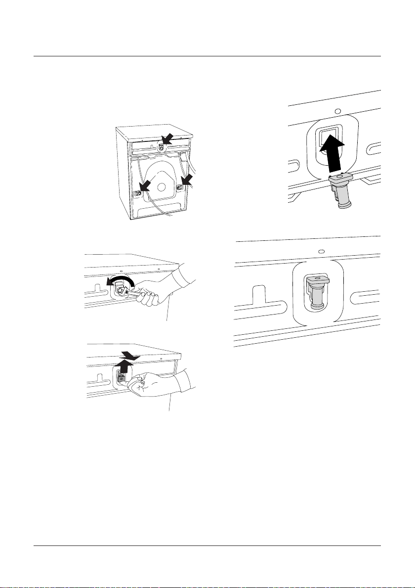
TRANSIT SCREWS
Before the machine can be used the three trans-
it screws must be removed as described below.
Each transit screw has a washer and a rubber
spacer. The rubber
spacers are used to
protect the screw ho-
les after the screws
have been removed.
1. First unscrew the screw and remove the was-
her.
2. Then pull out the rubber spacer.
3. Finally, refit the rubber spacers to cover the
transit holes.
WASHING MACHINE MECHANICAL INSTALLATION
6
Page 7
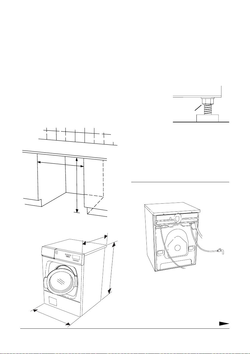
POSITIONING THE WASHING MACHINE
The washing machine can be built-in or free-
standing. It should be positioned so that there
is an electrical socket within easy reach.
A. Built-in
The washing machine can be built in under a
worktop with a working height of 850–900 mm.
Leave a 5 mm gap around the machine. This
also applies between the rear edge of the top
the machine and the wall behind.
min 600 mm
min 850 mm
B. Free-standing
The washing machine can be placed alongside
or underneath the tumble dryer.
585 mm
The machine can be anchored to the floor, see
enclosed bag containing instructions and parts.
ADJUSTING THE FEET
Adjust the feet so that the machine is level and
steady on the floor.
Tighten the lock-
ing nuts.
Locking nut
CONNECTING TO WATER SUPPLY
The machine should be connected to the water
supply by someone who has the necessary skill.
The machine is connected using the supplied
inlet hose.
NOTE!
It is important that you use the inlet hose that
is supplied, not an old hose.
1
2
3
4
5
6
7
8
m
50 m
8
The water pressure must be 0.1–1 MPa
(about 1–10 kp/cm
2
; 10–100 N/cm2).
The water supply pipe must be fitted with a
shut-off valve.
595 mm
If the supply pipe has just been installed we
recommend that it is flushed out thoroughly
MECHANICAL INSTALLATION WASHING MACHINE
7
Page 8
first to remove any dirt. Otherwise this could
clog the intake filter in the machine and block
the water supply.
WATER INTAKE – MIXED OR COLD WATER
On delivery the machine is set to use mixed hot
and cold water. The machine can be reset to use
only cold water or hot water.
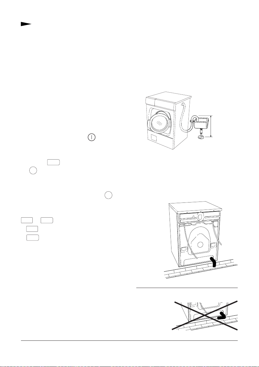
CONNECTING TO THE DRAIN
Machine with drain pump
The machine is supplied with a drain hose al-
ready fitted and this should be connected to a
laundry sink, or the like, at a height of 600–900
mm above the floor.
To change the water intake setting, do as
follows:
Switch off the power switch, , then switch
it on again so that the machine is in start-up
mode.
Press the
button five times, then press
8
the 4 button five times. You have to comple-
te these ten button presses within fifteen se-
conds.
Within three seconds of pressing the 4 but-
ton for the fifth time you must then select the
type of water intake you want by pressing the
or
6
6
8
buttons.
8
to use cold water only (C).
to use mixed hot and cold water (E).
A letter C near the bottom right of the dis-
play shows that cold water is being used and
the letter E indicates mixed hot and cold.
600-900 mm
The lower height (600 mm) is always prefera-
ble. Make sure the drain hose is not kinked.
Machine with drain valve
An outlet hose is supplied with the machine.
This must be connected to the outlet on the
machine and
empty into a
floor drain
or gutter
drain.
NOTE!
The end of the outlet hose must be lower than
the lowest
point of the
outlet valve.
WASHING MACHINE MECHANICAL INSTALLATION
8
Page 9

ELECTRICAL INSTALLATION
ELECTRICAL INSTALLATION
The washing machine must be connected using
a permanently installed cable through an isola-
ting switch by a qualified electrician.
Power supply
The machine is supplied, depending on market,
for one of the following supplies (see rating
plate):
A. 3-phase, 400V, 50 Hz supply, 10 A.
B. Single-phase, 230 V, 50 Hz supply, 13/16 A.
C. Single-phase, 230 V, 50 Hz supply, 10 A.
If an earth leakage circuit breaker is fitted it
must be of type A.
Reconfiguration
The machine can be reconfigured. The machi-
ne should be reconfigured as shown in the wi-
ring diagram underneath the top panel of the
machine.
NOTE!
Electrical connection /reconfiguring must be car-
ried out by a qualified electrician.
CONNECTING TO A COIN MECHANISM
Connection to a coin mechanism must be car-
ried out by a qualified electrician.
A special connecting cable is required to con-
nect the machine to a coin mechanism. This
can be ordered as a spare part, art. no. 92 090
95.
Recommendations for choice of coin mechanism
The connecting cable (92 090 95) supplies the
coin mechanism with power (230 V). The coin
mechanism must be able to short-circuit two
signal leads for a period of time (around 0–10
minutes). This is so that the user has time to
load the laundry, select the programme and start
the programme after inserting the coins.
ELECTRICAL INSTALLATION WASHING MACHINE
9
Page 10

CHANGING SETTINGS
LANGUAGE
You can change the language of the displayed
text.
The languages you can choose from are Dansk,
Deutsch, English, Espanol, Français, Italiano,
Nederlands, Norsk, Portugués, Suomi and
Svenska.
To change language do as follows:
Switch off the power switch, , then switch it
on again so that the machine is in start-up mode.
Press the
button five times, then press
8
the 1 button five times. You have to comple-
te these ten button presses within fifteen se-
conds.
Within three seconds of pressing the 1 but-
ton for the fifth time you should then select the
language you want by pressing the 6 or
7
buttons.
LOCKING A PROGRAMME
If for some reason you want to limit the number
of programmes that can be used you can lock
one or more programmes.
No characters or digits are shown on the dis-
play when a locked programme is selected.
To lock or unlock a programme, do as follows:
Switch off the power switch, , then switch it
on again so that the machine is in start-up mode.
Press the
the
7
-button five times, then press
8
-button five times. You have to com-
plete these ten button presses within fifteen se-
conds.
Within three seconds of pressing the
7
button for the fifth time you should hold in the
programme button for the programme you want
to lock for 5-10 seconds until the information
in the display starts flashing.
Then you can lock the programme by relea-
sing the programme button and pressing the
-button once.
Do the same to unlock the programme.
WASH TEMPERATURE - CENTIGRADE OR FAHRENHEIT
You can change the way the temperature is dis-
played from centigrade (C) to Fahrenheit (F).
To change the temperature display, do as follows:
Switch off the power switch, , then switch it
on again so that the machine is in start-up mode.
Press the
button five times, then press
8
the 2 button five times. You have to comple-
te these ten button presses within fifteen se-
conds.
Within three seconds of pressing the
button for the fifth time you should then press
the 6 or 7 buttons to select centigrade
(C) or Fahrenheit (F).
CHANGING PRESET WASH TEMPERATURE
You can change the preset wash temperatures
for each of the programmes. The temperatures
you can choose from are:
Heavy wash - C, 30, 35, …, 85, 90ºC.
Normal wash - C, 30, 35, …, 85, 90ºC.
Light wash - C, 30, 35, …, 85, 90ºC.
Synthetic wash - C, 30, 35, …, 85, 90ºC.
Super quick wash - C, 30, 35, …, 85, 90ºC.
Wool/hand wash - C, 30, 35, 40ºC.
2
WASHING MACHINE CHANGING SETTINGS
10
Page 11
If you choose C, the wash temperature will
be the same as the intake water temperature.
To change the wash temperature, do as follows:
Switch off the power switch, , then switch it
on again so that the machine is in start-up mode.
Press the
button five times, then press
8
the 6 button five times. You have to com-
plete these ten button presses within fifteen se-
conds.
Press the programme button, 1 -
, to
8
select the programme you want to change the
wash temperature for.
Then use buttons
(increase time) to choose the wash tem-
7
(reduce time) and
6
perature. As you scroll through to the chosen
temperature it appears at the bottom of the
display alongside the
symbol.
When your chosen wash temperature appears
press the
button again to confirm your
8
choice.
Within three seconds of pressing the
but-
3
ton for the last time you must then press the
or 7 button to choose whether you
6
want the child lock on or off.
Press
to activate the child lock.
7
Press 6 to disable the child lock.
CHILD LOCK ON BUTTON
To prevent accidental button pushes on the
button you can activate the child lock
function. The
button then must be held
in for three seconds to activate the machine.
To switch the child lock on or off, do as follows:
Switch off the power switch, , then switch it
on again so that the machine is in start-up mode.
Press the
button five times, then press
8
the 3 button five times. You have to comple-
te these ten button presses within fifteen se-
conds.
CHANGING SETTINGS WASHING MACHINE
11
Page 12

2
1
MAINTENANCE
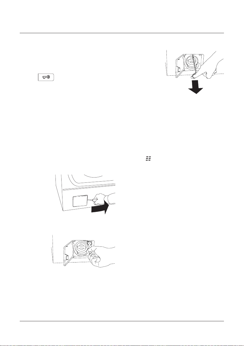
EMPTYING/CLEANING TRAP AND DRAIN PUMP
(only machines with drain pump)
The washing machine has a trap that is desig-
ned to catch coins, hair clips, etc. To clean the
trap and the drain pump, do as follows:
1. Make sure the machine is empty of water and
that the power switch is off.
2. Open the flap that conceals the drain pump
at the bottom
left of the mach-
ine. Use a screw-
driver as shown.
3. Pull the hose off the spigot inside the flap
and drain the water
into a suitable con-
tainer.
4. Open the pump by turning the cap anti-
clockwise. Remove
the cap and trap.
5. Remove any objects and waste from the pump
housing. Check
that the pump im-
peller at the back
rotates freely.
6. Screw the cap and trap back into place, re-
connect the drain
hose and close the
flap.
INSPECTION HOLES UNDER DRUM PADDLES
If you think that an item such as a nail, paper-
clip, hair clip or the like has fallen through the
wash drum you should inspect the outer drum
through the inspection holes in the paddles.
Items such as this can rust and produce stains
on clothes. Nails and other sharp items could
tear clothes.
Do as follows
1. Use a screwdriver or similar tool.
2. Insert the screwdriver
through the hole in
the middle of the
paddle and lever
the handle of the
screwdriver gently
to the left.
3. Grasp the rear edge of
the paddle cover
with your other
hand and pull it
towards you as
shown.
4. Lift off the paddle cover.
5. Examine the space between the inner and
outer drum as you turn the inner drum. Rem-
ove any items you see.
6. Engage the paddle cover in its locating holes
with the F marking nearest you. Make sure that
all the clips engage in their holes in the drum.
WASHING MACHINE MAINTENANCE
12
Page 13

Push the paddle cover away from you until it is
in its original position.
CLEANING THE DETERGENT DRAWER
Pull the drawer out as far as it will go.
Then lift it upwards and outwards as shown.
Wash and wipe clean the detergent compart-
ments.
NOTE!
Do not put the detergent drawer in a dishwash-
er!
CLEANING THE OUTSIDE OF THE MACHINE
Clean the outside and the programme panel
using mild detergent. Do not use abrasives or
solvents as they may damage the machine. Do
not spray the machine with water.
IN AREAS WITH HARD WATER
If the machine is installed in an area with hard
water a greyish white deposit may appear on
the wash drum. To remove this, empty a 20
gram packet of citric acid into the wash drum
and run a Normal wash programme at 85ºC.
You will find citric acid on the spice shelf at
your supermarket.
MAINTENANCE MAINTENANCE INTERVAL
Trap and drain pump 12 times a year or each 25 cycle
Inspection holes under drum paddles Twice a year
or each 150 cycle
Cleaning detergent drawer 12 times a year or each 25 cycle
Cleaning outside of machine As necessary or when cleaning
laundry room.
Hard water (greyish white deposit in drum) Twice a year
Maintenance chart for washing machine.
MAINTENANCE WASHING MACHINE
or each 150 cycle
13
Page 14
TROUBLESHOOTING
DOOR WILL NOT OPEN
1. Check that the power switch is on.
2. Has there been a power cut? Check the fuses
in the fuse box. The door cannot be opened
with the
3. If everything else fails the door can be ope-
ned in an emergency as follows:
• Make sure the power switch is off.
• Machines with a drain pump: First check that
there is no water left in the machine. If there is,
empty the machine as described under the
heading Checking trap and drain pump, in the
chapter on Maintenance.
• Open the flap at the bottom left. Use a screw-
driver as shown.
button if there is no power.
• Pull the handle to open the door.
• Press the handle back into its recess and secu-
re it with the screw. Close the flap.
If you have problems opening the door nor-
mally again, call service.
MACHINE DOES NOT START
1. Is the door shut properly? Push it firmly. A
flashing symbol appears in the display if the
machine is started with the door open.
2. Check if the child lock is activated. To start
the tumble dryer when the child lock is acti-
vated, hold in the start button for 3 seconds.
See Changing settings.
3. Is there power to the machine. Check the
fuse box.
• Unscrew the screw that holds the red plastic
handle.
WASHING MACHINE TROUBLESHOOTING
14
ERROR MESSAGES
The character display shows whether a fault has
occurred during the programme. To cancel an
error message after the fault has been corrected
as described below, switch off the machine or
change the programme.
You can check and fix some faults yourself:
Problem emptying. Machine not emptying pro-
perly. Check:
– that nothing has got stuck in the drain hose
outlet.
Page 15

– that the drain pump is not blocked by a fo-
reign object. Clean the pump, see chapter on
Maintenance.
– that the drain hose is not kinked.
After doing this, run programme P8. If there is
still a problem, call service.
Machine not filling. Fault in water supply, check:
- is the tap on the water pipe open?
- is the filter in the machine’s water intake bloc-
ked? Turn off the tap. Unscrew the hose and
check.
is flashing in the bottom right corner of the
display. The programme has tried to start but
the door is open. Close the door and start again.
THE DISPLAY IS LIGHTING WHEN A PROGRAMME
IS SELECTED, BUT NO CHARACTERS OR DIGITS
ARE SHOWN
No characters or digits are shown on the dis-
play when a locked programme is selected.
To unlock a programme, see Changing set-
tings.
WRONG LANGUAGE DISPLAYED
If the display language has changed for some
reason you can go back to the original langua-
ge.
The languages you can choose between are
Dansk, Deutsch, English, Espanol, Français,
Italiano, Nederlands, Norsk, Portugués, Suomi
and Svenska.
0000 is flashing at the top right of the display.
The machine has not spun.
1. The machine has a built-in imbalance sensor
that reduces the speed or prevents spinning if
the load is poorly distributed. Switch off the
power switch,
, then switch it on again.
Open the door and redistribute the load.
2. After doing this, run programme P8.
To change language do as follows:
Switch off the power switch, , then switch it
on again so that the machine is in start-up mode.
Press the
button five times, then press
8
the 1 button five times. You have to comple-
te these ten button presses within fifteen se-
conds.
Within three seconds of pressing the 1 but-
ton for the fifth time you should then select the
If there is some other fault, call service and say
which error message appears in the display.
TROUBLESHOOTING WASHING MACHINE
language you want by pressing the
buttons.
or
7
6
15
Page 16

CONTENTS - TUMBLE DRYER
SAFETY 17
General
Using the dryer first time
Child lock on Start/Stop buttons
Thermal cut-out
Float
Door
Packaging
Scrapping
PARTS OF THE TUMBLE DRYER 18
TECHNICAL INFORMATION 19
Technical data
Programme cycles
MECHANICAL INSTALLATION 20–25
Positioning the tumble dryer
Adjusting the feet
Condensed water
Venting
Reversing the door
CHANGING SETTINGS 28
Language
Locking the programme
Child lock
MAINTENANCE 30–32
Cleaning the outside of the machine
Cleaning the fan
Cleaning the condenser
Cleaning the lint filter
In areas with hard water
Emptying the condensation water tank
TROUBLESHOOTING 33–34
Machine will not start
Thermal cut-out
Drying takes too long
Error messages
The display is lighting when a program
me is selected, but no characters or
digits are shown
Wrong language displayed
ELECTRICAL INSTALLATION 26
Electrical installation
Connecting to coin mechanism
TUMBLE DRYER CONTENTS
16
Page 17

SAFETY
GENERAL
• Read and keep this manual!
• Any electrical work must be carried out by a
qualified electrician.
USING THE DRYER FOR THE FIRST TIME
When you start the dryer for the first time, or if
it has not been used for a long time, you may
hear a faint clunking noise. This is entirely nor-
mal and will disappear after a few cycles.
CHILD LOCK ON BUTTON
To prevent accidental button pushes on the
button you can activate the child lock
function. The
button then must be
held in for three seconds to activate the mach-
ine.
THERMAL CUT-OUT
The tumble dryer is protected by a thermal cut-
out. This switches off the machine if it gets too
hot.
DOOR
The tumble dryer has a magnetic lock, which
makes it easy to open the door from the outside
or inside. The door is fitted with a switch that
automatically switches off the tumble dryer
when the door is opened. The tumble dryer
does not start automatically when the door is
closed (for example if a child pulls the door
closed from the inside).
PACKAGING
Recycle the packaging according to recommen-
dations in your area.
SCRAPPING
At the end of its life the machine must be disa-
bled before being scrapped.
Contact your local recycling centre to find
out where to dispose of it or recycle it.
The machine has been built and marked to
facilitate recycling.
FLOAT (only applies to condenser dryer)
A float switches off the machine if there is a
blockage in the condensed water hose.
CAUTION!
During the programme, the back of the tumble
dryer will get very hot. Leave the machine to
cool completely before touching the back.
SAFETY TUMBLE DRYER
17
Page 18
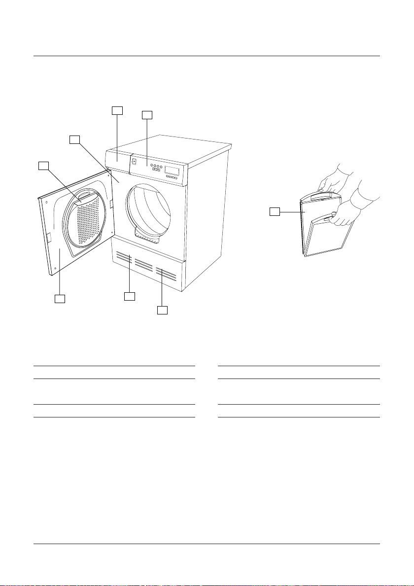
PARTS OF THE TUMBLE DRYER
3
2
1
5
6
1. LINT FILTER HOLDER
2. RATING PLATE
3. CONDENSATION WATER TANK –
CONDENSER TUMBLE DRYERS ONLY
4. PANEL
4
1
2
3
4
5
6
7
8
8
7
5. DOOR
6. FAN (BEHIND FRONT PANEL)
7. CONDENSER – ONLY CONDENSER TUMBLE
DRYERS (BEHIND FRONT PANEL)
8. LINT FILTER
TUMBLE DRYER PARTS OF THE TUMBLE DRYER
18
Page 19

TECHNICAL INFORMATION
TECHNICAL DATA
Height: 850 mm.
Width: 595 mm.
Depth: 585 mm.
Weight: 39 kg (vented) / 47 kg (condenser).
Drum capacity: 111 l.
Drying capacity: 6.0 kg.
Speed: 52 rpm.
Power rating: See rating plate.
Composition of drum: Stainless steel.
Composition of casing: Powder-painted and hot-dip galvanized sheet
steel or stainless steel.
Installation: Stacked, free-standing or built-in.
Drain (condenser tumble dryer): 2.0 m EPDM rubber hose.
Vent hose (venting tumble dryer): 3.0 m PVC.
PROGRAMME CYCLES
Cooling
(appr.
min)
20
20
20
20
20
20
P1 Extra dry
P2 Dry
P3 Normal dry
P4 Iron dry
P5 Extra dry
P6 Dry
Normal
Normal
Normal
Normal
Low
Low
Temperature
Drying
P7 Normal dry
P8 Iron dry
The length of the drying depends on the moisture of the items being dried. The time for drying shown in the table
above indicates the relative time for each programme.
TECHNICAL INFORMATION TUMBLE DRYER
Low
Low
20
20
19
Page 20

MECHANICAL INSTALLATION
POSITIONING THE TUMBLE DRYER
The tumble dryer can be installed free-stan-
ding, built-in or stacked on top of a washing
machine. Remember that the dryer generates
heat and should not therefore be placed in a
room that is too small. If the room is very small,
drying will take longer due to the limited volu-
me of air.
TIP!
To improve the air supply, leave open the door
of the room in which the dryer is placed.
WARNING!
Electrical installation must be carried out by a
qualified electrician.
A. Free-standing
The tumble dryer can be placed next to the
washing machine. The dimensions of the tum-
ble dryer are:
585 mm
1
2
3
4
5
6
7
8
B. Built-in
The tumble dryer can be built in under a work-
top with a minimum height of 850 mm. The
gap must be at least 600 mm wide.
min 600
min 850
103
120
135
140
C. Stacked
The tumble dryer can be stacked on top of an
Electrolux Wascator WE 50 washing machine.
Use the stacking kit that is supplied with the
machine:
2 plastic holders. Plastic bag inside the drum.
m
2 metal tip guards. Attached to the lower back
of the machine.
850 m
120
140
595 mm
An optional pull-out top can be purchased
from your dealer: Art no. 80 619 07-0 (white)
and 80 619 07-33 (black).
TUMBLE DRYER MECHANICAL INSTALLATION
20
Page 21

Fit the stacking kit as follows:
1. Unscrew the two arrowed screws at the rear of the
washing machine.
2. Fit the metal brackets as shown, using the screws.
3. The plas-
tic cups that will hold the front feet of the tumble
dryer must be attached to the top of the washing
machine. This is important since the feet of the
tumble dryer must be located in the plastic cups to
ensure that the dryer is correctly positioned.
Break tab A off the cup that goes on the right side
and break tab B off the cup that goes on the left
side. Then peel the
backing paper off the
self-adhesive base of
the cups.
A
B
4. Position the plastic cups so that the arrowed lugs
are flush with the front
and side of the top, then
press down onto the top.
Now break off the re-
maining tabs.
5. Open the knock-out holes on the back of the
tumble dryer (where present)
with the aid of a hammer and
screwdriver. They must not
be fully removed, just ope-
ned!
6 Slide the tumble dryer
under the metal brackets,
keeping the front edge rai-
sed 1–2 cm.
7. Lower the front feet of the
dryer into the plastic cups and
adjust the feet so that the dry-
er is level.
ADJUSTING THE FEET
Screw the feet in or out until the dryer is
steady and level
on the floor or
washing machi-
ne. Then tighten
the locking nuts.
Locking nut
MECHANICAL INSTALLATION TUMBLE DRYER
21
Page 22

CONDENSED WATER
(only applies to condenser tumble dryer)
The machine is supplied with a 2.0 metre-long
drain hose. Use this to remove the condensed
water.
max 1000 mm
NOTE!
It is important that you use the new rubber
hose that is supplied, not an old hose.
VENTING
(only applies to venting tumble dryer)
The exhaust air from the tumble dryer must be
led to a ventilation duct or a wall outlet using
the accompanying vent hose.
Connect the vent hose as follows:
1. Slide the vent hose over the end of the adap-
ter and secure with the plastic strap.
2. Remove the plastic cover from the hole if you
intend to connect the hose to a hole other than
the one that is already open.
3. Insert the end of the adapter in the hole.
4. Fit the cover to the open hole.
Connecting to vent duct
The vent hose must follow the shortest, straigh-
test path possible from the tumble dryer to the
vent duct. Cut the vent hose to length if it is
too long. If necessary the vent hose can be ex-
tended to a maximum length of 8 metres (inter-
nal diameter 102 mm). If a longer hose is requi-
red it must have a larger internal diameter in
order to maintain the fan capacity of the dryer.
Any bends should be as gentle as possible. If
Connecting to tumble dryer
The tumble dryer can be vented in three ways:
Examples of
installations
from the rear, from the right
side or from the left side.
One of the holes is open
when the dryer is delivered.
The other two
are fitted
with covers.
The tumble dryer is supplied
1
2
3
it is necessary to make 90º bends there must be
no more than four of them. More bends reduce
the fan capacity of the dryer.
with an adapter (1), a plastic collar (2) and a
vent hose (3).
TUMBLE DRYER MECHANICAL INSTALLATION
22
Page 23

Installation in warm climates
When installing in temperatures above 25°C
(77°F) with a high level of humidity, do not
route the air exhaust hose upwards.
The hose must always run downwards or stay
level with the tumble dryer.
Condensation problems
If the hose is long and the room is cold, con-
densation will form inside the hose. This is una-
voidable.
If the air exhaust hose is slack, water may
build up at the low points, blocking he air flow.
To avoid water build-up in the hose or that
water runs back into the machine, drill a hole
(Ø3 mm) at the lowest point in the hose and
put a water collector underneath.
If there is only one vent duct from the room
then a vent spacer must be fitted, article num-
ber 92 059 01.
Vent spacer
REVERSING THE DOOR
The dryer is supplied with the door hinged on
the left side. You can reverse the door so that
the hinge is on the right side
Do as follows:
1. Remove the lower front panel and unscrew
the three screws that hold the door hinge brack-
et.
Accessories
If the vent hose is ta-
ken to a wall outlet you
can prevent cold air
getting in by fitting a
ventilation grille, artic
le number 9205900.
The ventilation grille
Ventilation grille
Door hinge
bracket
can be installed inside or outside.
MECHANICAL INSTALLATION TUMBLE DRYER
23
Page 24

2. Pull the bottom edge of the door outwards
while twisting the hinge bracket in the direc-
tion shown by
the arrows.
3. Move the hinge pin to the other side of the
bracket. When the door is hung
on the right side the hinge brack-
et must be turned upside down.
Hinge pin
4. Then transfer the hinge pin in
the underside of the top panel to the right side.
6. Unscrew the two screws from the edges of
the door about five millimetres so that you can
remove the door magnet and plate from the
inside of the door.
7. Lift out the door magnet (1) and plate (2).
1
2
8. Refit the door magnet where the plate was.
5. Now transfer the plastic plugs in the top and
bottom of the door to the right side of the door.
Use a screwdriver to prise them out.
TUMBLE DRYER MECHANICAL INSTALLATION
24
9. Refit the plate where the magnet was.
Page 25

1
3
2
10. Screw in the screws to secure the door mag-
net and plate.
11. Unscrew the arrowed
screw. If the dryer is a con-
denser model you must also
open the cover over the con-
denser.
12. Now fit the door to the right side of the
machine.
13. Fit the hinge bracket, tightening the screws
in the order shown.
14. Refit the screw you unscrewed in step 11.
15. Refit the lower front panel.
1
2
2
2
2
1
2
MECHANICAL INSTALLATION TUMBLE DRYER
25
Page 26

ELECTRICAL INSTALLATION
ELECTRICAL INSTALLATION
The washing machine must be connected using
a permanently installed cable through an isola-
ting switch by a qualified electrician.
Configuration on delivery
The machine is configured for a single-phase,
400V supply, has a heating output of 3000 W
and is fitted with a 10 A fuse. If an earth leaka-
ge circuit breaker is fitted it must be of type A.
It is possible to reconfigure the dryer for a sing-
le-phase supply, see below.
Reconfiguring
The machine can be reconfigured for single-
phase, 10 or 16 A. Reconfiguring for single-
phase requires a 3-core cable with a plug. The
machine should be reconfigured as shown in
the wiring diagram underneath the top of the
machine.
Single-phase, 230 V, 50 Hz, heating output
1950 W, fuse 10 A.
Single-phase, 230 V, 50 Hz, heating output
2500 W, fuse 16 A.
NOTE!
Electrical connection /reconfiguring must be
carried out by a qualified electrician.
Connecting the tumble dryer and washing
machine together
Wiring the two machines together as described
below must be carried out by a qualified elec-
trician.
To ensure a uniform load on the phases when
installing the tumble dryer together with an
washing machine for single-phase operation the
phases should be connected as follows:
Tumble dryer:
Terminal marked L1 to phase 1.
Terminal marked L2 to phase 2.
Terminal marked L3 to phase 3.
Washing machine:
Terminal marked L1 to phase 1.
Terminal marked L2 to phase 2.
Terminal marked L3 to phase 3.
CONNECTING TO A COIN MECHANISM
Connection to a coin mechanism must be car-
ried out by a qualified electrician.
The coin mechanism must be connected bet-
ween the tumble dryer’s power lead and the
wall socket.
TUMBLE DRYER ELECTRICAL INSTALLATION
26
Page 27
DELIBERATELY WHITE PAGE
ELECTRICAL INSTALLATION TUMBLE DRYER
27
Page 28

CHANGING SETTINGS
LANGUAGE
You can change the language of the displayed
text.
The languages you can choose from are Dansk,
Deutsch, English, Espanol, Français, Italiano,
Nederlands, Norsk, Portugués, Suomi and
Svenska.
To change language do as follows:
Switch off the power switch, , then switch it
on again so that the machine is in start-up mode.
Press the
the
button five times. You have to comple-
1
button five times, then press
8
te these ten button presses within fifteen se-
conds.
Within three seconds of pressing the
but-
1
ton for the fifth time you should then select the
language you want by pressing the
or
7
6
buttons.
LOCKING A PROGRAMME
If for some reason you want to limit the number
of programmes that can be used you can lock
one or more programmes.
No characters or digits are shown on the dis-
play when a locked programme is selected.
To lock or unlock a programme, do as follows:
Switch off the power switch, , then switch it
on again so that the machine is in start-up mode.
Press the
the
7
-button five times, then press
8
-button five times. You have to com-
plete these ten button presses within fifteen se-
conds.
Within three seconds of pressing the
7
button for the fifth time you should hold in the
programme button for the programme you want
to lock for 5-10 seconds until the information
in the display starts flashing.
Then you can lock the programme by relea-
sing the programme button and pressing the
-button once.
Do the same to unlock the programme.
CHILD LOCK ON BUTTON
To prevent accidental button pushes on the
button you can activate the child lock
function. The
button then must be
held in for three seconds to activate the mach-
ine.
To switch the child lock on or off, do as follows:
Switch off the power switch, , then switch it
on again so that the machine is in start-up mode.
Press the
the
button five times. You have to comple-
3
button five times, then press
8
te these ten button presses within fifteen se-
conds.
Within three seconds of pressing the
ton for the last time you must then press the
or 7 button to choose whether you
6
want the child lock on or off.
Press
Press
to activate the child lock.
7
to disable the child lock.
6
-
but-
3
TUMBLE DRYER CHANGING SETTINGS
28
Page 29

DELIBERATELY WHITE PAGE
29
Page 30

MAINTENANCE
1
4
3
5
2
CLEANING THE OUTSIDE OF THE MACHINE
Clean the outside and the programme panel
using mild detergent. Do not use abrasives or
solvents as they may damage the machine. Do
not spray the machine with water.
NOTE!
Do not let dust collect around the machine.
Keep the area around the dryer clean and cool.
Heat and moisture prolong the drying time.
CLEANING THE FAN
Once a year check whether the fan needs clea-
ning.
1. Switch off the power switch.
2. Remove the lower front panel.
3. Remove the safety screw (1). Prise out the
four clips in the
order shown and
remove the fan
cover.
4. Hold the fan and unscrew the nut.
5. Take out the fan and clean it with water and
a brush.
6. Refit the fan and tighten the nut.
7. Refit the fan cover, making sure the clips
hold the cover
in place. Don’t
forget to fit the
safety screw.
8. Refit the front panel.
2
2
1
30
TUMBLE DRYER MAINTENANCE
2
2
Page 31

CLEANING THE CONDENSER
The condenser should be cleaned at least six
times a year, or more often if the user has pets.
1. Switch off the power switch.
2. Remove the front panel.
3. Open the cover over the condenser by tur-
ning the two
levers anti-
clockwise.
4. Take out the condenser and wash the fins
using a hand shower. Do not poke anything
into the gaps bet-
ween the fins as
this could dama-
ge the conden-
ser. Do not use
any sharp metal
objects when cle-
aning.
NOTE!
Do not try to clean the condenser in a dis-
hwasher.
5. Refit the condenser. Make sure you put it in
the right way
up. The top
of the con-
P
P
U
P
U
N
E
B
O
denser is mar-
ked “upp”, “up”
and “oben”.
6. Refit the front panel.
2
2
2
2
1
MAINTENANCE TUMBLE DRYER
31
Page 32

IN AREAS WITH HARD WATER
1
2
If the machine is installed in an area that has
hard water this can produce a limescale deposit
on the lint filter.
When you clean the lint filter check if there
is any limescale deposit. If there is, wash out
the lint filter by hand.
1. Grasp the filter handle
and pull it towards you.
2. Slide the filter out of the
filter holder.
3. Open the filter
and rub off any
lint with your
hand. Rinse out the
filter to remove any
limescale deposit.
4. Fold the filter and put it back in the filter
holder.
CLEANING THE LINT FILTER HOLDER
Dust and dirt can gather in the bottom of the
lint filter holder. Take out the lint filter and use
a vacuum cleaner to clean the filter holder.
EMPTYING THE CONDENSATION WATER TANK
(only applies to condenser tumble dryer, when
drain hose isn’t used)
Empty the condensation water tank after each
tumble drying.
Pull out the condensation
water tank, empty the
water and put the tank
back.
If the tank becomes
too full the program will be interrupted. Empty
the tank and press the
-button and the
program will continue from where it was inter-
rupted.
MAINTENANCE MAINTENANCE INTERVAL
Clean the outside of the machine As necessary or when cleaning
the laundry room.
Clean the fan At least once a year or each 300 cycle
Clean the condenser Approx. 6 times a year or each 50 cycle
Clean the lint filter and lint filter holder After each tumble drying
Maintenance chart for tumble dryer.
TUMBLE DRYER MAINTENANCE
32
Page 33

TROUBLESHOOTING
MACHINE WILL NOT START
Check
• that the door is closed properly.
• if the child lock is activated. To start the tum-
ble dryer when the child lock is activated, hold
in the start button for 3 seconds. See Changing
settings.
• that the power switch is pressed in.
• that the plug (if fitted) is plugged in.
• that the fuse in the fuse box has not blown.
Try switching two fuses with the same rating.
• that the thermal cut-out has not tripped, see
below.
OVERHEATING PROTECTION
The dryer is designed with an overheat protec-
tion switch that will automatically turn the
machine off if the temperature gets too high.
The machine will not start until it has cooled
down sufficiently.
If the unit shuts down because of overheating,
check that the lint filter exhaust hose, vent duct,
and the condenser unit are free of lint. These
components need to be cleaned on a regular
basis. Additionally, the lint filter may need to
be cleaned with warm, soapy water and a soft
brush a few times a year to ensure the filter
screen is not blocked. Using dryer sheets (not
recommended) can also cause this problem.
Should the machine turn itself off because of
overheating, it will not be possible to restart
the unit until it has cooled down sufficiently.
This could possibly take up to thirty minutes.
To restart the unit once it has cooled down,
press the ”Start” button.
NOTE:
If your dryer overheats frequently, it may not be
vented properly or the room in which it is loca-
ted may not have sufficient air circulation. Con-
tact your installer to have these issues checked
out.
DRYING TAKES TOO LONG
Check that the lint filter and condenser are not
clogged, see the Maintenance chapter. The dry-
ing time may also be long if a condenser dryer is
placed in too small a room or if the air in the
room is too warm. Make sure the dryer has
access to more cool air, for example by opening
doors and/or windows.
ERROR MESSAGES
The character display shows whether a fault has
occurred during the programme. To cancel an
error message after the fault has been corrected
as described below, switch off the machine or
change the programme.
You can check and fix some faults yourself:
Over flow. Indicating that the condensation
water tank is full or that the lower water maga-
zine is full, due to the pump or hoses being
clogged or malfunctioning. Empty the tank and
check to ensure there are no kinks or blockage
in the hose. If this does not help, call service.
TROUBLESHOOTING TUMBLE DRYER
33
Page 34

Maximum programme duration. After the
machine has run for the maximum time (3
hours) it automatically stops. Check and repla-
ce any blown fuses in the fuse box. To cancel
the error message, switch off the machine or
open the door. If this does not work, call servi-
ce.
Sensor fault. Faulty moisture sensor. This error
message may also appear if you run the machine
with dry clothes or no clothes at all. Open the
door and the error message should disappear. If
not, call service.
If there is some other fault, call service and say
which error message appears in the display.
THE DISPLAY IS LIGHTING WHEN A PROGRAMME
IS SELECTED, BUT NO CHARACTERS OR DIGITS
ARE SHOWN
No characters or digits are shown on the dis-
play when a locked programme is selected.
To unlock a programme, see Changing set-
tings.
To change language do as follows:
Switch off the power switch, , then switch it
on again so that the machine is in start-up mode.
Press the
the
button five times. You have to comple-
1
button five times, then press
8
te these ten button presses within fifteen se-
conds.
Within three seconds of pressing the
but-
1
ton for the fifth time you should then select the
language you want by pressing the
or
7
6
buttons.
WRONG LANGUAGE DISPLAYED
If the display language has changed for some
reason you can go back to the original langua-
ge.
The languages you can choose between are
Dansk, Deutsch, English, Espanol, Français,
Italiano, Nederlands, Norsk, Portugués, Suomi
and Svenska.
TUMBLE DRYER TROUBLESHOOTING
34
Page 35

SERVICE
SERVICESTELLEN POINTS DE SERVICE SERVIZIO DOPO VENDITA
Zürich/Mägenwil
5506 Mägenwil
Industriestr. 10
9000 St. Gallen
Vonwilstrasse 15
4127 Birsfelden
Hauptstrasse 52
8604 Volketswil
Hözliwiesenstrasse 12
6032 Emmen
Buholzstrasse 1
7000 Chur
Comercialstrasse 19
3063 Ittingen/Bern
Ey 5
ERSATZTEILVERKAUF POINT DE VENTE DE RECHANGE VENDITA PEZZI DI RICAMBIO
1028 Préverenges
Le Trési 6
1950 Sion
Rue de la Piscine
6916 Grancia
Zona Industriale E
5506 Mägenwil
Industriestrasse 10
Tel. 0848 848 023
KOCHBERATUNG / VERKAUF DEMONSTRATION / VENTE CONSULENTE (CUCINA) / VENDITA
8048 Zürich
Badenerstrasse 587
Tel. 01 405 81 11
GARANTIE GARANTIE GARANZIA
Wir gewähren auf allen
Produkten, die in der
Schweiz gekauft und in
Betrieb sind, eine einjährige Vollgarantie, gerechnet ab Lieferdatum
an den Endver-braucher. Massgebend für den
Garantieanspruch ist die
Faktura oder ein entsprechen-der Verkaufsbeleg
5506 Mägenwil
Industriestrasse 10
Tel. 0848 848 023
8048 Zürich
Badenerstrasse 587
Tel. 01 405 81 11
L’utilisateur final de
tout produit acheté et
utilisé en Suisse, bénéficie d’une garantie
complète d’une année à
partir de la date de livraison. La facture ou le
justificatif d’achat correspondant fait foi en la
matière.
5506 Mägenwil
Industriestrasse 10
Tel. 0848 848 023
8048 Zürich
Badenerstrasse 587
Tel. 01 405 81 11
Per questo prodotto
concediamo una garanzia di 12 mesi a partire
della data di vendita. La
garanzia è valida dietro
presentazione della fattura o dello scontrino
d’acquisto.
35
Page 36

INDEX
WASHING MACHINE
Adjustable feet 7
Centigrade or Fahrenheit 1 0
Changing preset wash
temperature 1 1
Child lock 3
Cleaning 1 3
Coin mechanism 9
Connecting to drain 8
Connecting to water 7,8
Detergent drawer 4,13
Door 3,4,14
Drain pump 12,14
Drum paddles 1 2
Emergency open 1 4
Error messages 1 4
TUMBLE DRYER
Adjustable feet 21
Child lock 17,28
Cleaning 3 0
Coin mechanism 2 6
Condensed water 2 2
Condenser 18,31
Connecting washing machine and tumble dryer
together 2 6
Door 17,18
Page
Page
Hard water 13
Page
Hardness of water 13
Imbalance sensor 1 5
Inspection holes 1 2
Installation, electrical 9
Installation, mechanical 6
Language 10,15
Locking programme 1 0
Maintenance 1 2
Overfill cut-out 3
Packaging 3
Parts of washing machine 4
Positioning 7
Programme cycles 5
Page
Installation, electrical 26
Installation, mechanical 20
Language 28,34
Locking the programme 2 8
Maintenance 3 0
Packaging 1 7
Parts of the dryer 1 8
Positioning 2 0
Programme cycles 1 9
Rating plate 4
Page
Safety precautions 3
Scrapping 3
Technical data 5
Transport 3
Transit screws 6
Tra p 1 2
Troubleshooting 14
Winter storage 3
Page
Safety precautions 17
Scrapping 17
Stacking the dryer 20
Technical data 1 9
Thermal cut-out 17,33
Troubleshooting 33
Ventilation 2 2
Error messages 3 3
Float 1 7
Fan 18,30,32
Art. No. 80 806 73. Rev. 01. The right to make changes is reserved.
Printed on environment friendly paper.
36
Reconfiguring 2 6
Reversing door 23
 Loading...