

Page 1
820 41 72 58
USER
USER
s MANU
s MANU
AL -
AL -
NO
NO
TICE DUTILIS
TICE DUTILIS
AATION -
TION -
MANU
MANU
AL DEL USU
AL DEL USU
ARIO
ARIO
TCW 1990
ICE LINING REFRIGERATOR FREEZER
GB
REFRIGERATEUR / CONGELATEUR
A PAROI REFRIGERANTE - ILR
FRIGORIFICO/CONGELADOR
REVESTIDO DE HIELO
F
E
Page 2
USER MANUAL
2
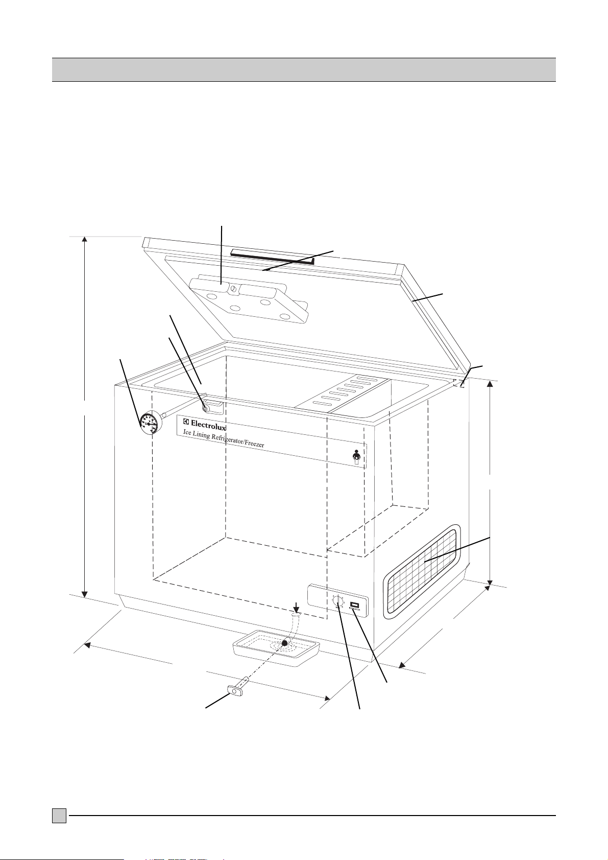
ICE LINING REFRIGERATOR FREEZER
Handle
Lid ice accu
Rubber gasket
Data label
Thermometer
850
1050
630
1465
Compressor
compartment
Pilot lamp ON
Thermostat for
refrigerator function
Drain plug
Locking device
Interior wall
Page 3

1. GENERAL INFORMATION......................................................page 4
2. INSTALLATION .....................................................................page 5-9
3. PREPARATIONS....................................................................page 10-11
4. USE THE APPLIANCE ...........................................................page 12
5. DEFROSTING & CLEANING ..................................................page 13-14
6. PERIODIC OBSERVATIONS/CHECKS/ACTIONS .....................page 15
7. TROUBLE SHOOTING ...........................................................page 16-17
(A) ILR not working
(B) Compressor is working,
but cabinet temperature is higher than normal
(C) Cabinet temperature is lower than normal
(D) Abnormal noise in the ILR
8. SHUTTING DOWN ................................................................page 18
9. STORAGE OF VACCINES IN THE ILR .....................................page 18
INDEX
3
Page 4

THE ILR
One of the most important links in the cold-chain is Ice
Lining Refrigerator (ILR). This is a unit which operates
on the principle of vapour compression system,
similar to any conventional compressor type
refrigerator operating on 1 15 or 230 volts, A.C. mains
supply. However, the ILR has top opening door to
prevent loss of cold air during door opening.
ICE LINING
The Icelined Refrigerator and Freezer has a icebank
inside the cabinet. The ice bank consists of frozen
icepacks during its operation. During periods of
power failure and load procedures, the ice bank acts
as cold storage to protect the vaccines. The ice bank
keep the temperature is not above +8°C for 30 hours.
HOLD OVER TIME
In case of power failure this unit is capable to hold the
temperature (if all the ice-packs are installed) inside
the Refrigeration compartment between 2 and 8°C
under following conditions.
Ambient temperature: Minimum hold over:
32°C 30 hours
43°C 20 hours
POWER SUPPLY
The ILR is fitted with heavy duty compressor which
requires low starting current and can also operate
within a range of voltage variations.
E.g. if the normal operating voltage is 230 volts, 50
Hz., A.C., it can work even when the supply voltage
occasionally go as low as 150 volts or as high as
280 volts.
THERMOMETER
To enable to measure the temperature inside the
cabinet without opening the lid, a thermometer is
provided with its dial on the front side. This makes
monitoring of the vaccine temperature easy.
LOCKING SYSTEM
The ILR is equipped with a lock, operated with a
key.
POWER-SUPPLY ARRANGEMENT
For smooth functioning of the ILR it is advisable to
connect the same to a 15 Amps power plug socket
outlet, wired from the mains with PVC insulated
cables of minimum 2.5 mm section of Aluminium
(see also page 5 under `Installation'). The larger
size of the plug and socket decreases the contact
resistance which in turn reduces voltage drop and
provides an easy path for the current.
Safety of the personnel and the equipments can not
be guaranteed unless the earth wire (green/yellow)
of the cord is really earthed. It is advisable to have
the earth connections to the socket checked by a
competent electrician.
VOLTAGE STABILIZER
Though the ILR is capable of operating within a
wide range of voltage variations, for extra safety one
separate Automatic Voltage Stabilizer should be
used with it.
1. GENERAL INFORMATION
4
Page 5
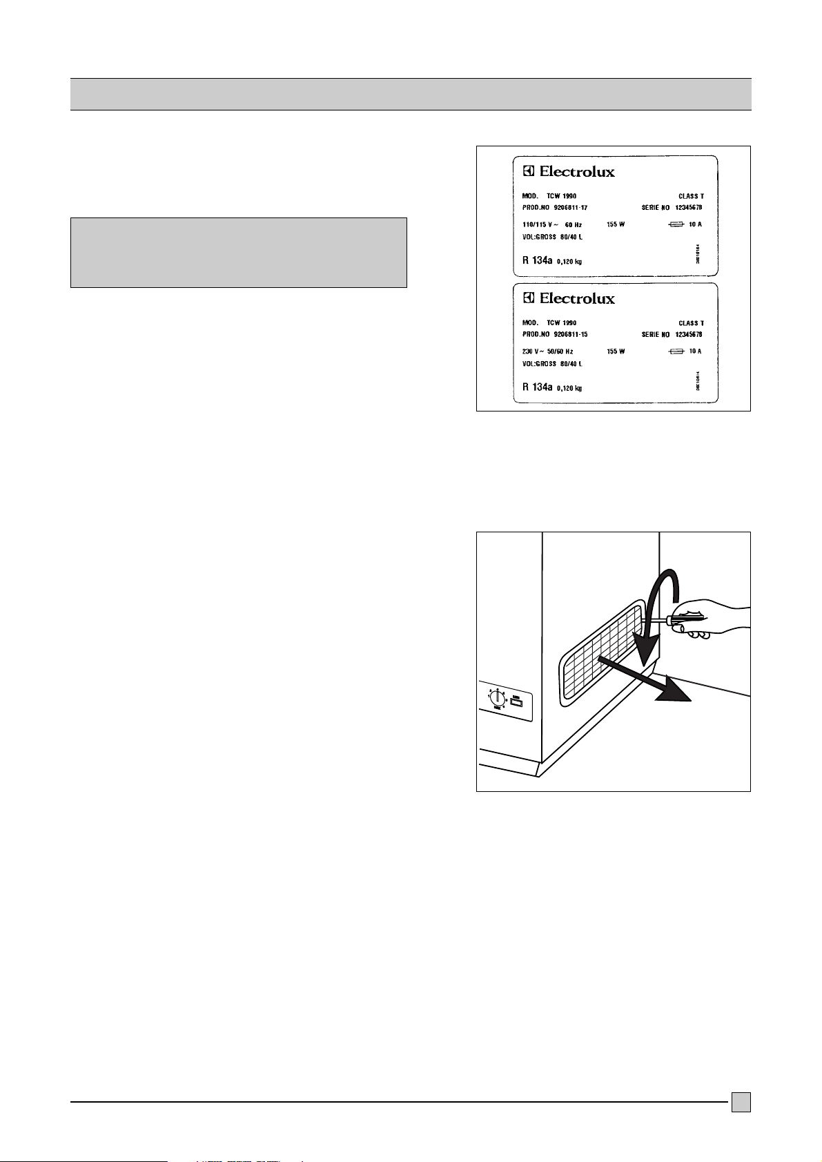
Check the manufacturer's plate, at the back of the ILR
and make sure that the ILR has correct voltage for
local supply, i.e. 1 15 or 230 volts (fig. 1).
CAUTION
Connecting the equipment to wrong supply
voltage may damage it.
If you have received equipments of wrong voltage
ratings, notify concerned authorities and keep the
equipments repacked.
The ILR is to be installed in a well ventilated room,
avoiding direct sunshine or any other source of heat.
Power supply socket (15 amps socket with switch,
fuse and mains indicator lamp is advisable) should be
available nearest to the place of installation of the ILR.
1.
Unscrew and remove the screws holding the side
cover of the compressor compartment on the right
hand side of the ILR and remove carefully the side
cover (fig. 2)
2. INSTALLATION
5
Fig. 2.
Fig. 1.
Page 6
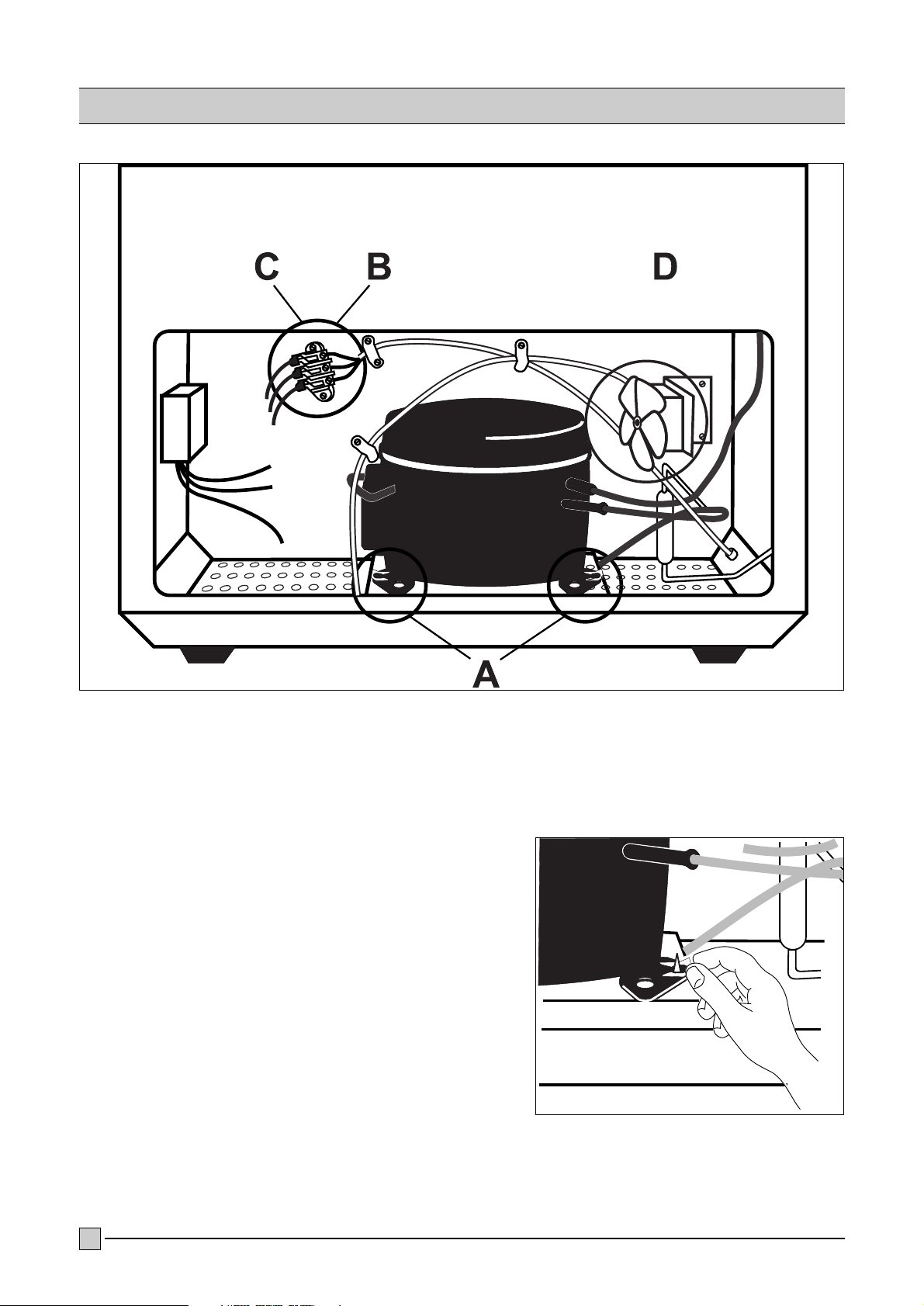
3.
EXAMINE the compressor compartment (fig. 3;
Check carefully for any damage, dislocation or
looseness etc. of the components, specially at
locations A, B. C, and D as below and rectify if
necessary.
LOCATION A (fig. 4)
Check that all 4 mounting brackets of the compressor
are in place and secured.
2. INSTALLATION
6
Fig. 4.
Fig. 3.
Page 7

LOCATION B (fig. 5)
Check that the incoming electrical connections of the
power supply cord to the terminal strip are tight.
LOCATION C (fig. 6)
Check that the outgoing electrical connections from
the terminal strip are tight.
LOCATION D (fig. 7)
Check that the mounting brackets of the fan are tight
and also that the fan blades are free to rotate.
2. INSTALLATION
7
Fig. 5.
Fig. 6.
Fig. 7.
Page 8

8
4.
Refit side cover of the compressor compartment into
position refixing the screws holding the side cover (fig. 8)
5.
INSTALL firmly the ILR on a level
floor, preferably on wooden
blocks or on a wooden platform to
protect it from damp and dirt.
(fig. 5)
Leave sufficient space on all sides
of the ILR, keep it away from the
walls for good circulation of air
around it, see below:
Back and left side should be
minimum 3 cm away from the
walls (fig. 9a)
Hinges can be pushed against the
wall
Right side should be minimum
10 cm away from the wall (fig. 9b)
6.
The ILR has 4 supporting legs. If
the ILR is not in a level and stable
position, adjust this by adding
wooden blocks or similar under
the legs.
2. INSTALLATION
Fig. 8.
Fig. 9.
Fig. 9a
Fig. 9b
Page 9

9
7.
Connect the leads of the power supply cord to a
suitable 3-pin plug as shown below (fig. 10)
Lead of cord Pin of plug
Green/yellow Earth
Blue Neutral
Brown Phase
CAUTION:
DO NOT CONNECT THE ILR TO POVER SUPPLY
NOW
2. INSTALLATION
Fig. 10.
Page 10

10
1.
Open the lid of the appliance. Unscrew the the lid
ballast container. (fig. 11)
2.
Unscrew the cap of the lid ice accu and fil it with clean
water.
3.
Unscrew the 3 frame screws and remove the plastic
Refrigerator innerliner. (fig. 12)
4.
Remove all 36 ice-packs from the ice bank and the 5
ice-packs in the refrigeration compartment.
5.
Plug in the appliance for test. The green lamp
indicates that the unit is under power. (fig. 13)
6.
Check in the compressor compartment that the
compressor starts and the fan on the left side is running.
7.
Check that the blower in the bottom of the dividing wall
is running. Check by pushing with your fingers to the
flap thermostat, if a free moving to open and close the
cold air channel is granted.
3. PREPARATIONS
Fig. 11.
Fig. 12.
Fig. 13.
Page 11

11
8.
Fill the ice-packs to the marked level and screw on
the cap. To remove the cap, you press on the cap
from the top and simultaneously you turn the cap
anticlockwise. With your finger nail or a small
screw driver you push of the plastic protection.
(fig. 14)
9.
Put the 5 (filled with water) small ice-packs in the
bottom of the refrigeration compartment. (fig. 15)
10.
Fill all the 36 ice-packs with water, tight the cap
carefully and stack them in the greater freezing
compartment.
It is important that they are stacked exactly as
shown on the sketch in order to obtain air
circulation through the ice-packs and in order to
avoid damages caused by expansion during
freezing. (fig. 16)
11.
After correct installation of all the ice-packs insert
the plastic innerliner and fix it with his 3 screws.
12.
Refit the filled ballast container on the lid.
13.
Check that the drainage plug is always at his
position.
3. PREPARATIONS
Fig. 15.
Fig. 16.
Fig. 14.
Page 12

12
1.
Close the lid and plug in the appliance. The green
indicator light on the front control panel shows you
that the unit is switched on. (fig. 17)
2.
Turn the thermostat button to the position 1"
(20°C ambient) or at 2" (32°C ambient) and
leave the unit for minimum 48 hours. After this
time, check if the ice-packs in the ice bank are
completely frozen.
If you find after 48 hours that the temperature on
the front thermometer is warmer then the desired
range from 2 to 8°C you can adjust the thermostat
button to position 3" or 4".
If you find after 48 hours that the temperature on
the font thermometer is colder then the desired
range from 2 to 8°C you must check if the water
in the ballast container is frozen. If this is the case
you have to check the flap thermostat.
3.
When the temperature on the front thermometer
is observed to be steady for several hours within
the range from +2° to +8°C only then the
vaccines to be preserved should be transferred to
the ILR. (fig. 18)
4.
After storing the vaccines keep the lid properly
closed and locked.
5.
The inner temperature of the cabinet can fluctuate
due to several reasons:
to high ambient temperature,
to many openings of the lid,
to many vaccines at on time,
inner arrangement of the vaccines,
air circulation around the unit,
inner blower is not running.
4. USE THE APPLIANCE
Fig. 17.
Fig. 18.
Page 13

13
DEFROSTING & CLEANING
The moisture in the air, which enters the ILR due to lid
opening (and also may be due to defective lid-gasket
or door alignment) is attracted by the cold surfaces
inside the ILR. So, formation of frost and ice occurs
on the walls around the tubes inside the lining
compartment. When the frost layer is 1 /4" to 1 /2"
(6-12 mm) thick, it is time for `defrosting' the ILR.
MOST IMPORTANT:
Before defrosting the ILR, the vaccines preserved in it
will have to be removed and stored temporarily in
other working ILR or Refrigerator.
If a second ILR or Refrigerator is not available, the
vaccines will have to be preserved in Cold-Box or
Vaccine carrier, properly lining the same with frozen
ice packs, such that the vaccine temperature remains
within the recommended storage temperature during
the defrosting of the ILR.
DEFROSTING & CLEANING
PROCEDURE
1.
When the frost formation around the evaporator is 6 to
10 mm thick, it is time for Defrosting".
2.
Prepare the temporary storage and transfer the
vaccines to another refrigerator or cold box.
3.
Unplug the unit and open the lid for minimum 24 hours
so that all the ice around the evaporator and the ice
bank can melt.
4.
Open the drainage plug at the bottom, inside the
cabinet.
Keep a suitable container under the drain hose to
collect the defrost water. (fig. 19)
5. DEFROSTING & CLEANING
Fig. 19.
Page 14

14
5. DEFROSTING & CLEANING
5.
Unscrew the plastic innerliner and remove them.
6.
Remove all the ice-packs and store them in a transport
box, so that they not defrost at all.
7.
Use a scrapper the remove the ice formation around
the surfaces, never use a hairdryer to melt the ice
formation.
8.
Before you insert the ice-packs again you must be
sure that all the inner parts are absolutely dry.
9.
Check that the blower and the flap thermostat are
working correctly.
10.
If everything is 100% dry, you can insert the plastic
innerliner. Don´t forget to refit the drainage plug.
Page 15

15
DAILY
1.
Take temperature readings from the thermometers
and note down the temperature and the time of
reading.
Keep the temperature records systematically. It is
suggested that minimum 2 readings should be taken
(in the morning and afternoon) preferably at the same
hours of each day.
If the temperature is observed to be below or above
the required range, adjust the thermostat by steps,
allow the ILR to run for about one hour under
observation. If required, adjust the thermostat further
until the required temperature range is obtained.
To make the inside colder, the thermostat knob is to
be turned clockwise to a higher setting.
To make the inside warmer, the thermostat knob is to
be turned anti-clockwise to a lower setting.
2.
Check if the inner blower is running (by feeling the air
flow with your hand).
WEEKLY
1.
Check if ice formation has started around the
evaporator and the ice bank. Prepare for defrosting.
2.
Check if the gasket if not broken and if it seals tight
against the frame.
3.
Check if the ballast container in the lid is not frozen.
MONTHLY
1.
Clean the compressor compartment:
a) Put off the switch, if any, and take out the plug
from the wall socket.
b) Take out the side-cover of the compressor
compartment (see page 5, actions 1 ). Clean the
interior of the compressor compartment with a
soft brush.
c) Check the mounting brackets of compressor and
the bolts of the fan, if they are tight. If not, rectify.
d) Fit back the side cover (see page 8, actions 4)
2.
Clean the lid seal.
3.
If possible, put a standard mercury thermometer
inside the cabinet and compare the readings with
those of the dial thermometers and see if they are
correct.
Dial thermometers with incorrect readings may have
to be re-adjusted or replaced, as incorrect readings
may lead to wrong storage temperature and loss of
the potency of the vaccines preserved.
6. PERIODIC OBSERVATIONS/CHECKS/ACTIONS
Page 16

16
IMPORTANT:
When an ILR is found to be not working at all or not
working properly, see that the vaccine temperature is
within the recommended limits.
Do not open the lid unless very essential.
Observe temperature from time to time and if you feel
that temperature may exceed the higher limit before
the ILR is repaired - transfer the vaccines to other
working ILR/refrigerator or cold-box.
If required use smaller pieces of commercial ice in
polythene bags in the cold-box - in absence of frozen
ice packs.
For any abnormal sound, smoke, smell etc. in the ILR
disconnect the plug from the wall socket and notify
refrigerator technician.
A) THE ILR IS NOT WORKING
1. Observe the `green' mains-on indicator light on
right on the front panel.
a) IF NOT GLOWING
I) Check if wall socket switch is OFF.
II) Check if the voltage stabilizer, if any, is working
or not.
III)Check if power supply is available at the wall
socket. This can be tested by connecting an
electric lamp or other appliances to the socket.
The lamp should glow or the appliances should
work, if supply is available at the socket.
If not available:
There may be some defect in the power supply circuit
(viz: blow-off fuse, loose connections, faulty switch or
socket, single phasing etc.) which should be rectified
through competent Electrical Maintenance
Technicians.
If power is available at the socket:
IV Check that the plug is inserted properly into the
socket.
V Check the plug for loose connection or
dislocation of power supply cable connections -
rectify if required.
VI)Remove the plug from socket. Check the
incoming and outgoing cable connections on the
terminal strip in the compressor compartment
(see page 6 & 7, actions 3B and 3C)
VII) Even after actions as above, the `yellow' lamp
is not glowing - Notify Refrigerator Technician.
b) IF GLOWING
I) Observe if the compressor cooling fan is
working. If the fan is working but the
compressor is not running - Notify Refrigerator
Technicians.
II) If the fan, too, is not working, check the
thermostat setting, if it is wrongly turned
completely anti-clockwise. If so, turn it
clockwise to a higher setting and observe if
the fan and the compressor are working now.
If working - Allow the ILR to run and adjust
thermostat to obtain recommended temperature.
If not working - Notify Refrigerator Technician.
B) COMPRESSOR IS WORKING, BUT
CABINET TEMPERATURE IS HIGHER
THAN NORMAL
NOTE:
The cabinet temperature may go little higher than
normal, but should come down after some time
when:
New vaccines are stored
The lid is opened frequently or kept open for
longer duration
Unfrozen ice packs are put in for freezing.
1.
Check if recommended space is left on back and
sides of the ILR for air circulation (see page 8,
action 6.
2.
Check if there is too much frost formation in the
liner chamber on the inside walls. If so, defrost (see
page 13 for Defrosting and Cleaning)
3.
Check if the compressor is cut `off' by the
thermostat before required temperature is attained.
If so, adjust thermostat setting.
7. TROUBLE SHOOTING
Page 17

17
4.
If the compressor is observed to be running
continuously but no cooling is attained - this may be
due to leakage of refrigerant gas from the system or
defect in the unit, - Notify Refrigerator Technician.
5.
Check if the compressor tries to start but trips-off early
by the over-load protector. This may be either due to
too low supply voltage or defect in the compressor or
starting relay - put `off' the ILR till return of normal
voltage and try to run once again. If the defect
prevails, - Notify Refrigerator Technician.
C) CABINET TEMPERATURE IS
LOWER THAN NORMAL
Turn the thermostat knob, anti-clockwise, to a lower
setting and observe if the compressor is cut `off' by the
thermostat. If the same does not cut `off' even at the
lowest (1) setting, the thermostat may be defective and
may have to be replaced - Notify Refrigerator Technician.
NOTE:
In such cases, till the repair is done, the vaccines
should be preserved as follows
a) Take out the floors and the layer of ice packs
b) Put one layer of fresh (non-frozen) ice packs o n
the bottom and replace the floors
c) Keep some not-frozen ice packs on and around the
vaccines also
d) Run the ILR under surveillance and put it `off' when
lowest recommended temperature is attained. Put
the ILR `on' again when the highest recommended
temperature is reached and keep it running until the
lowest recommended temperature is attained
again. Repeat as above till the ILR is repaired.
D) ABNORMAL NOISE IN THE ILR
In case of any abnormal noise coming out from the
ILR, try to locate the source of the noise. Generally
it may come from the compressor compartment. In
such cases,
1. Take out the plug of the ILR from socket and
open the side cover of the compressor
compartment (see page 5, actions 1 )
2. Examine if the mounting brackets of the
compressor are in place and secure, and if the
mounting bolts for the fan are tight. If required
replace broken or lost brackets and tighten loose
bolts (see page 6 & 7, fig. 4 & 7)
3. Check if any pipe or component has come out of
its position and also touching others. If so, rectify
carefully.
4. Check if the ILR is level and firm on its base. If
not, rectify.
5. Even after actions as above if it is observed that
the noise is still present or it is coming from the
inside of the compressor - Notify Refrigerator
Technician.
7. TROUBLE SHOOTING
Page 18

18
IF THE ILR IS TO BE SHUT DOWN FOR
TRANSPORTATION ETC.
Disconnect the power-supply plug from socket
Allow the ice in the liner tuber (if any) to melt and
pour out the water completely and put back the
plugs on the tubes
Defrost and clean the interior
Leave the lid open till the ILR is absolutely dry ·
Roll the power supply cord into a coil and bind
and place it carefully to avoid damage
8. SHUTTING DOWN
FOR STORING VACCINES
1.
Keep the packets containing the vaccines in neat
rows,
2.
Different vaccines should be kept separately to
facilitate easy identification.
3.
Keep about 2 cm space between rows for circulation
of air.
4.
Store DPT & TT vaccines, not touching the inside walls
or bottom of the ILR. It is better to keep them in the
baskets.
5.
Keep a separate thermometer among the vaccines to
ascertain the actual vaccine temperatur
9. STORAGE OF VACCINES IN THE ILR
Page 19

19
 Loading...