

Page 1
MANUAL CARAVAN
RA/RM-2D
0402
RM 4601
RM 4801
Deutsch Seite 3
English page 12
Français page 21
822 70 89-00
Page 2

Page 3

OPERATING AND INSTALLATION INSTRUCTIONS
FOR ELECTROLUX REFRIGERATORS
INTRODUCTION
We are pleased that you have chosen this refrigerator
and hope you will derive muc h satisf action from using it,
but first a few well-meant words of advice:
It is important to read through these instructions carefully before using the refrigerato r.
T o ensur e good refrigeration and economical oper ation,
the refrigerator must be installed and used as described
in these instruction
The refrigerator is designed for installation in caravans
or campers.
TRANSIT DAMAGE
Inspect the refrigerator for damage. Transit damage
must be reported to whoever is responsible for delivery
not later than seven days after the refrigerator was
delivered.
DATA PLATE
Check the data plate, inside the refr igerator, to ensure
that you have received the right model.
The data plate contains e. g. the following details:
Model designation RM................................
Product number ......................................
Serial number ......................................
V oltage ...................................... volts
Gas pressure ...................................... mbar
Since these details will be needed if you hav e t o contact
service personnel, it is a good idea to make a note of
them here.
CONTENTS
OPERATING INSTRUCTIO NS .............. ............. 13
CONTROLS ............................ ....................... 13
STARTING THE REFRIGERATOR .............. 13
WINTER OPERATION ................................ .. 13
REGULATING T HE TEMPERAT URE .. ...... .. 13
TRAVEL CATCH ........................................... 13
FOOD STORAGE .......................................... 13
ICE-MAKING ............ ........ ........ ........ ........ ..... 14
DEFR O STING ...... .............. .................. ......... 14
CLEANING THE REFRIGERATOR .............. 14
TURNING OFF THE REFRIGERAT OR ......... 14
IF THE REFRIGERATOR FAILS
TO WO R K .................. ................................ ... 14
MAINTENANCE . .............. .......................... ... 15
SERVICE .... .......................... .................... .... 15
INSTALLATION INSTRUCTION ....................... 15
REPOSITIONING THE HINGES ................... 15
DOOR PANEL ................... ........ .......... ........ . 15
INSTALL ATI ON/BUI LDING-IN .............. .... ... 15
VENTILATION OF THE UNIT ...... .... ...... ...... . 17
LP GAS CONNECTION .............................. .. 17
ELECTRICAL CONNECTION ...................... 18
TECHNICAL DATA ....................................... 19
12
Page 4
OPERATING INSTRUCTIONS
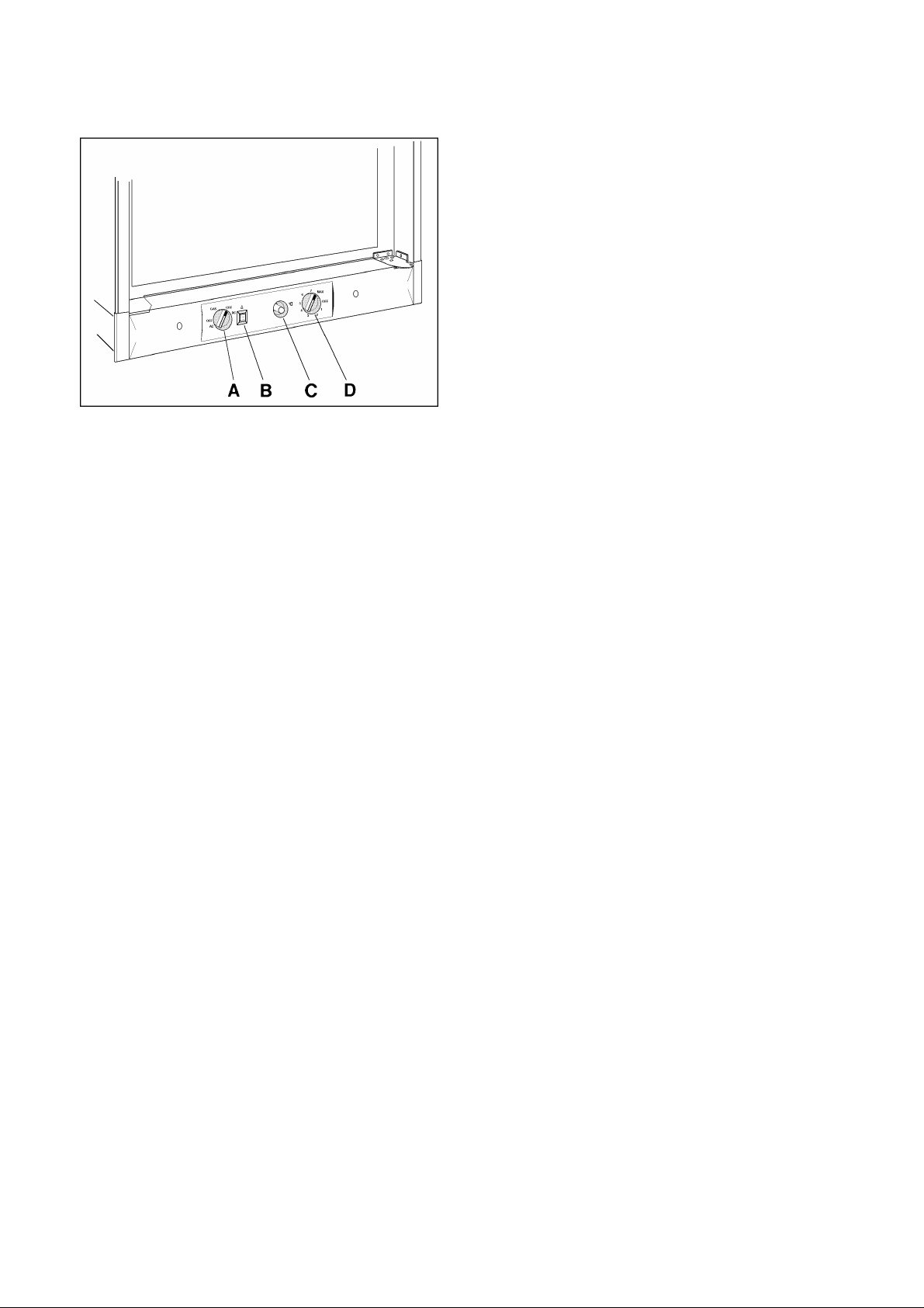
CONTROLS
FIG. 1
The refrigerator can be run on either 230-240 V,12 V or
LP gas. Changing between t hese modes of operation is
carried out by means of the control buttons positioned
as shown in fig. 1.
The energy selector (A) can be set at either "AC" (230240 V), "DC" (12 V), "GAS" (LP gas) or "OF F" .
5. When the flame lights, th e spark ing stops aut o mati cally and the lamp stops flashing.
6. Keep the knob (C) depressed for another 10-15
seconds to activate the flame failure device, then
release it.
If the lamp start flashing again, repeat step 4-6.
To terminate gas operation, turn the knob (A) to "OFF"
position.
230-240 V operation
Before taking the refrigerator into operation, check that
the voltage stated on the data plate is the same as the
main voltage in use.
• Turn the thermostat knob (D) to its highest (coldest)
position.
• Set the energy selector (A) to position "A C".
12 V operation
Only operate your refriger ator on 12 V when the engine
of the vehicle is running - otherwise your battery will soon
be discharged.
• Set the energy selector (A) to position "DC".
An indicator lamp (B) at the control panel flashes when
the automatic igniter at tem pts to light the b u rner. Otherwise this lamp is off.
The refrigerator is fitted with a safety device which
automatically shuts off the supply of gas if the flame goes
out. The safety device can be opened manually by
depressing knob (C).
The refrigerator temperature is controlled by a thermostat (D) when the refrigerator runs on 230-240 V and LP
gas. Please note that the thermostat has no "off" position
when the refrigerator runs on LP gas.
STARTING THE REFRIGERATOR
All references are to fig. 1.
LP Gas operation
After initial installation, servicing, or changing gas cylinders
etc., the gas pipes ma y co ntain some ai r wh ich shoul d b e
allowed to escape by brie fly turni ng on the ref rige rator or
other appliances. This will ensure that the flame lights
immediately.
To start gas operation:
1. Open the shut off valve of the gas bottle (check that
there is enough gas). Open any on-board shut-off
valve.
2. Set the thermostat knob (D) to the highest setting.
3. Turn the energy selector (A) to position "GAS".
A ticking sound will be heard and the lamp (B) will
start flashing.
4. Press the button (C ). This opens the flame failure
device and allows gas to fl ow to th e burn er.
WINTER OPERATION
Please check that the vent ilation grilles or the flue outlet
are not blocked by snow, leaves etc.
Some caravans with outside ventilation may have so
called winter covers, to protect the cooling unit against
cold air (ask your dealer). The covers may be fitted when
the outside temperature is below approx. 10°C and
should be fitted when the temperature is below the
freezing point.
We suggest that you fit the winter covers also in the case
that the vehicle is laid up during the winter months.
REGULATING THE TEMPERATURE
The position number ref ers to fig.1.
It will take a f ew hours for the r efrigerator to reach normal
operating temperature. So we suggest you start it well
in advance of a trip and if possib le store it with precooled
foodstuffs.
On 230-240 V operation and LP gas operation the
refrigerator is controlled by a thermostat and the thermostat knob (D) should be set at 3-5. If a lower (colder)
temperature is desired, set the thermostat to a higher
figure.
On 12 V operation the refrigerator works continuously.
TRAVEL CATCH
The travel catch is integrated in the handle. Make sure
that the travel catch is engaged when the cara v an is on
the move.
FOOD STORAGE
Always keep food in closed containers. Never put hot
food in the refrigerator; allow it to cool first.
Never keep items in the refrigerator which might
give off flammable gases.
13
Page 5

The frozen food com partment is intended f or the storage
of frozen food and for making ice. It is not suitable for
freezing items of food.
Never put bottles or cans of fizzy drinks in the frozen
food storage compartment as they may burst when
freezing.
Most kinds of frozen food can be stored in the frozen
food compartment for about a month. This period of time
may vary, however, and it is important to follow the
instructions on the individual packages.
ICE MAKING
It is practical to make ice during the night - then the
refrigerator is less demanded and the cooling unit has
more reserves. Fill the ice tr ay to just below t he brim with
drinking water and place it on the freezer shelf.
It is possible to make ice faster by turning the control
knob temporarily to its highest value but do not forget to
turn it back to its regular setting afterwards as the
refrigerator might otherwise become too cold.
The exterior of the refrigerator should be wiped clean
now and then, using a damp cloth and a small quantity
of detergent. But not the door gask et, which should only
be cleaned with soap and water and then thoroughly
dried.
The cooling unit behind the refrigerator should be
cleaned with a brush from time to time, but make sure
that the refrigerator is switched off when doing this.
TURNING OFF THE REFRIGERATOR
If the refrigerator is not to be used for some time:
1. Set the switch (A), fig. 1, to "OFF".
2. Shut off any on-b oard valve in the gas line to the
refrigerator.
3. Empty the refrigerator. Defrost and clean it as described earlier . Lea ve the doors of the refrigerator
and frozen food compartment ajar.
4. When the vehicle is laid up fo r a long perio d o f time
(e.g. during the winter months), we suggest fitting the
winter covers on to the grills.
DEFROSTING
Frost will gradually accumulat e on the refrigerating surfaces. It must not be allowed to grow too thick as it acts
as an insulator and adversely aff ects ref rigerator perf ormance. Check the formation of frost regularly every
week and when it gets about 3 mm thick, defrost the
refrigerator.
To defrost the refrigerator , turn it off and remov e the ice
trays and all food items, leave the cabinet and freezer
doors open.
Do not try to accelerate defrosting by using any kind of
heating appliance, as this might damage the plastic
surfaces of the refrigerator. Neither should any sharp
objects be used to scrape off the ice.
The defrost water runs from a collector channel to a
receptacle at the rear of the refrigerat or where it normally
evaporates.
Heavy frost build up on the freez er plate and the cooling
fins, and a lot of defrost water:
Move the plastic drain tube in to a water tight bucket or
container . (Access through the lower ventilation grill on
the outside of the vehicle). As the frost melts, the water
will flow into the container. Replace the drain tube to its
original position after defrosting.
Defrost water in the freezer compartment should be
mopped up with a cloth.
When the ice has melted, wipe the refrigerator dry and
restart it. Place the food items back inside but wait until
the refrigerator is cold before making ice cubes .
CLEANING THE REFRIGERATOR
Clean the inside of the refrigerator regularly to keep it
fresh and h ygienic.
Soak a cloth in a solution consisting of a teaspoon of
bicarbonate of soda to half a litre of warm water. Wring
out the cloth and use it to clean the interior of the
refrigerator and its fittings.
Nev e r use d ete r ge nt s , s co ur in g p o wd er, str o ng ly scente d
products or wax polish to clean the int erior of the ref rigerator as they may damage the surfaces and leave a
strong odour.
IF THE REFRIGERATOR FAILS TO WORK
Check the following points bef ore calling a service technician:
1. That the "STARTING THE REFRIGERATOR"
instructions have been followed.
2. The refrigerator is level.
3. If it is possible to sta rt the refrigera tor on any o f the
connected sources of energy.
4. If the refrigerator fails to work on gas, check:
• That the gas bottle is not empty.
• That all LP-gas valves are open.
5. If the refrigerator fails to work on 12 V, check:
• That the 12 V supply is connected to the refriger-
ator.
• That the fuse on the 12 V supply is intact.
• That the battery is not run down.
6. If the refrigerator fails to work on 230-240 V, check:
• That the 230-240 V supply is connected to the
refrigerator.
• That the fuse is intact.
If the refrigerator is not cooling sufficiently, the
reason may be:
1. Inadequate venti lation of th e cooling uni t due to the
intake and/or exhaust air vents being partly or completely blocked.
2. The evaporator is frosted up.
3. Incorrect thermostat settings.
4. Incorrect ga s pre ssure - please check the p ressu re
regulator on the gas container.
5. The am b i en t te m p er at u r e is too hig h.
6. To much food is loaded at one time.
7. The door is not properly closed or the magnetic
sealing strip is defective.
If the refrigerator still does not work properly, call
a service technician.
14
Page 6

The sealed cooling system must not be opened,
since it contains corroding chemicals under
high pressure.
MAINTENANCE
Always turn to a qualified service technician who is
familiar with LP gas systems and refrigerator.
We recommend that a service technician check the
refrigerator once a year .
• Check all connections in the LP gas system for gas
leaks. Connections can be tested for leaks using a
soap solution. Do not use a naked flame! If there is
any suspicion of damage, call f or a service technician.
• The ventilation openings are unobstructed.
• The Instruction Manual is av ailable.
• Check that the burner is clean and free from combus-
tible material.
SOME USEFUL HINTS
Make sure that:
• The refrigerator is not operating on 12 V when the
vehicle is parked, otherwise you will drain the car
battery in a short time.
• Defrosting is carried out periodically
• The refrigerator is clean and dry with the door left
open when it is not to be used for some time.
• Liquids or items with a strong odour are well pack ed.
• The ventilation openings are unobstructed.
• The door is secured by means of the travel catch
when the caravan is on the mov e .
When mounting the panel, proceed as follows.
See figure 8.
• open the door 90 degrees
• remove the door decoration strip from the door by
taking out the 3 scre ws and remove the old panel
• inse rt the new p anel an d p u s h the pa n e l d o wnwards
• replace the decoration strip and screws
INSTALLATION/BUILDING-IN
The refrigerator is intended for installation in a caravan
or camper van, and the description relates to this application.
The refrigerator must not be exposed to radiated heat
from hot objects ( e.g. below a cooker without proper heat
shielding).
Excessive heat irradiation impairs performance and
leads to increased energy consumption. F or this reaso n
the refrigerator should be installed if possible not at the
entrance side of the vehicle - normally orientated south
and often with an awning - which would impair the
dispersion of heat and combustion gases from the
ventilation openings.
It is not a good practice to install the refriger ator s o that
the vent openings are cov ered by the v ehicle’ s entranc e
door when this is set open. This would reduce the
ventilation air flow to the cooling unit and reduce refrigeration performance.
The enclosure
The refrigerator must be installed in a substantial enclosure and must be level, the dimensions are shown in
TECHNICAL DATA.
SERVICE AND SPARE PARTS
Service and spare parts are obtainable from your dealer
or Electrolux - consult the telephone directory.
INSTALLATION INSTRUCTIONS
REPOSITIONING THE HINGES
The refrigerator is equipped with convertible doors.
A special door rev ersing kit must be used t o change door
swing.
Fo r further information , contac t your dealer or Electrolux.
DOOR PANEL
Door panels can easily be fitted or changed. The dimensions of the panels must be:
Model RM 4601 RM 4801
Height upper door 402 402 ±1mm
lower door 826 982 ±1mm
Width 525 525 ±1mm
Thickness max. 4 4 mm
The bottom of the enclosure must be horizontal and e ven
so that the refrigerator can be easily pushed into place.
It must be sturdy enough to carry the weight of the
refrigerator.
Make sure that there is a comp lete seal b etween th e
front frame of the refrigerator and top, sides and
bottom of the enclo sure.
A length of sealing strip is applied to the rear surface of
the front frame for this purpose, see fig. 2.
Note: A wood strip must be in place across the upper
opening of the enclosure. The top frame of the refrigerator will be anchored to the wood str ip with screws. See
fig. 6 b.
Push the refrigerator into the recess until the sealing
strip on the flange seals against the front of the recess,
so that the cooling unit is completely sealed off against
the interior of the caravan.
Note: Be careful not to damage the sealing s trip when
the refrigerator is put in place.
The refrigerator is delivered with door panels.
15
Page 7

2
FIG . 2
Securing the refrigerat or
After the refrigerator is put in place, (insuring a comb ustion seal at the front frame), the refrigerator is to be
secured in the enclosure with six screws. The screws
have to be installed in the following order:
A. T wo screws installed throug h the front base.
1. Secure the refrigerator to the floor with two screws:
One screw through the hinge and into the floor, and
on the opposite side one screw through the front
base. (See Fig. 3).
2. A cover plate (shipped as a loose part) is to be
attached after the refrigerator is secured in the
enclosure. (See Fig. 3).
FIG. 4
Seal the opening for the screws with aluminium tape.
Replace the top decoration panel. Make sure the tabs
snap back into the holes in the hinge plate.
C. Two screws installed in the rear base.
See fig. 5.
Failure to f ollow the sequence in securing the refrigerator
in the enclosure can cause leakage between the frame
and cabinet. Any space between the counter, storage
area or ceiling and top of the refrigerator greater than
40 mm should be blocked. The heat produced at the rear
of the refrigerator will become trapped in this space,
making the top of the refrigerator hot and reduce the
efficiency of the refrigerator .
1
FIG. 3
B. T wo screws installed in the top frame.
The top decoration panel must be removed from the
refrigerator befor e the screws c an be installed. Open t he
upper door and gently push the tabs out of the hole in
the hinge (both sides) with a flat blade screwdriver.
Carefully tilt the top decoration panel and lift up to
remove from top fram e. See fig. 4.
Install the two screws in the top frame, the holes are
accessible from underneath.
16
FIG . 5
Page 8

Minimum
ventilation
height
VENTILATION OF THE UNIT
NOTE: Wood Strip
MUST be in place
Minimum
ventilation
height
Condenser
FIG. 6a
Ventilation heights
Model Minimum ventilation heights in mm.
Installation with upper Installation with roof vent
and lower side vent. and lower side vent.
RM 46 01 1760 1515
RM 48 01 1900 1670
At high ambient temperatures the refrigeration unit will
only perform adequately when properly ventilated.
The ventilation passage at the rear of the recess, between the outer wall of the vehicle and the refr igerator
must be completely sealed off from the interior of the
caravan. Neither flue gas nor (cold) air from the ventilation openings in the wall of the caravan (outer wall of the
ventilation passage) must be able to pass int o the interior
of the caravan.
The side walls of the shaft should be thermally insulated
to prevent condensation and cold draughts. Shaft wall
sections located abo v e and below the exhaust gas vent
must not be made of flammable materials.
Proper installation requires one lower fresh air intake
and one upper exhaust vent (fig. 6a).
These should have a free flow-through area of at least
400 cm
Fresh air enter s through the lower opening and warm air
is discharged through the upper exhaust vent.
The lower opening should be located at floor level ( to
allow any leaking gas to escape to the outside).
The ventilation of the cooling unit can also be done via
two openings in the wall of the caravan (fig. 6 b).
Fresh air enter s through the lower opening and warm air
is discharged through the upper one.
2
.
FIG . 6b
The upper ventilation opening should be located above
the condenser, as high as possible, to ensure good
ventilation.
The lower opening should be located at floor level ( to
allow any leaking gas to escape to the outside).
The openings in the caravan wall must be fitted with
suitable grilles with sufficient heat resistance. These
should have a free flow-thr ough area of at least 400 cm
Please observe that fly netting behind the grilles can
reduce the area by as much as 50%.
If there is no outer grille at floor lev el where leaking gas
can escape, a 40 mm hole to the outside should be made
in the floor of the rec ess to dr ain an y unb urnt gas to t he
outside.
Fit the hole with wire m esh and an angled plate to prot ect
it from stones, mud etc.
LP GAS CONNECTION
The refrigerator is designed for operation on LP gas, the
press ure of whi ch must be 28 mbar f or Butane and 37 mbar
for Propane. Chec k that this is stated on the data plate.
The refrigerator is not design ed for operati on on
town gas or natural gas.
CAUTION! CHECK THAT THE GAS SUPPLIED
TO THE REFRIGERATOR IS AT THE CORRECT
PRESSURE. SEE THE REDUCING VALVE ON
THE LP GAS CONTAINER.
The gas installation should only be carried out by a
person experienced in gas fitting. It is recommended that
the gas pipe feeding the refrigerator is so arr anged that
it is possible to turn off the supply of the refrigerator.
It must be of a type approved for use with continuously
operating bottled gas appliances, and have threaded
compression connections throughout. PUSH-ON CONNECTIONS MUST NOT BE USED (We do not recommend the use of "rubber" type flexible tubing for
2
.
17
Page 9

connecting permanently operating appliances of this
type in the United Kingdom). All connectors etc. should
be of a type specifically designed for the type and
diameter of the connection pipe used, and screwed
joints should be seale d with a joinin g comp ound approve d
for use with bottled gas.
The gas supply pipe should be connected to the gas inlet
pipe (outside diameter 8 mm) by means of a suitable
gas-tight compression fitting, e.g. olive.
In making the connection to the refrigerator , a union gas
cock of an approved type bottled-gas must be incorporated in the supply line in a position which is readily
accessible to the user. For e ventual se rvicing purposes,
the union should be on the outlet side of the cock and
the pipework should be positioned so as not to prevent
the refrigerator from being readily withdrawn.
On completion of installat ion , the system must be
pressure tested by a qualified tech nician .
ELECTRICAL CONNECTION
The electrical installation must be carried out in a proper
and durable manner, taking into account all relevant
regulations and codes of practice. For mains voltage
operation, it is important that the circuit t o and in the
caravan is eff ectiv ely earthed.
For connection to a 230-240 V electricity supply, the
refrigerator has a 3-core mains lead which is intended
for connection to a properly earthed plug and socket
outlet. The socket outlet should be fitted in the caravan
in a position readily accessible to the user , within reach
of the mains lead. In the United Kingdom, the plug and
socket outlet should be of the non-reversib le type .
As the colours of the wires in the mains lead of this
appliance may not correspond with the coloured markings identifying the terminals in your plug, proceed as
follows:
- the wire which is coloured Green and Yellow must be
connected to the terminal in the plug which is mark ed
with the letter E or by the earth symbol , or
coloured Green or Green and Yellow,
- the wire which is coloured B lue must be connected t o
the terminal which is marked with the letter N or
coloured Black,
- the wire which is coloured Brown mus t be connect e d
to the terminal which is marked with the letter L or
coloured Red.
fitted with a 3 amp. fuse, ASTA approved to B.S. 1362.
In other countries, the fuse rating will depend upon the
voltage and local practice.
230-240 V Supplies.
Check that the voltage stated on the data plate is the
same as the mains voltage in use (230-240 V).
Plug the 230-240 V refrigerator power cord into an easily
accessible wall socket .
Electrical leads must be routed and secured so
that they cannot come into contact with hot or
sharp parts of the refrigerato r.
12 V Supplies
The 12 V connection of the refrigerator is shown in fig. 4.
Connect the refrigerator to the vehicle battery or alternator by a direct cable, (check the polarity).
The connection is made to the terminal block (fig. 7
"Heater"). T o avoid a voltage drop, the c ross section area
of the connecting cable between battery/alternator and
the refrigerator must be 10 mm
To ensure satisfactory operation, the posit iv e lead m ust
be fitted with a fuse rated at max. 25 A.
To prevent the refrigerator from draining the battery,
make sure that the current supplied t o the caravan is cut
off when the vehicle engine is not running, for example
by fitting an ignition control relay.
2
.
12 V supply of reigniter and interior light
The reigniter and the interior light must be connected to
a separate 12 V battery.
Connect the battery to the te rminal b lock ( fig. 7 "Reigniter, Lamp"). Be careful not to make the wrong positive
and negative connections.
The reigniter should not be connected directly to a
battery charger but only over a battery.
Interior lig ht - bulb - change
If the bulb has to be replaced, proceed as follows:
1. Remove cover of the lamp by pushing it backwards.
2. Remove the bulb.
3. Put in a new bulb (12 V, max. 5 W).
Spare part number for bulb: 200 72 90-03.
4. Push the lamp cover back in place.
WARNING- THIS APPLIANCE MUS T BE EARTHE D
IMPORTANT
The wires in this mains lead are coloured in accordance
with the following code:
- green/yellow: ear th
- blue: neutral
- brown: live
In the United Kingdom, the plug or circuit to the refrigerator must be fitted with a fuse not greater than 5 amps.
If a 13 amp. (B .S. 1363) fused plug is used, it should b e
18
FIG. 7
Page 10

TECHNICAL DATA
RM 4601 RM 4801
Overall dimensions, refrigerator
Height (incl. controls) ........... 1427 1583 mm
Width ................................... 632 632 mm
Depth (incl. handle).............. 668 668 mm
Recess dimensions
Height .................................. 1415 1571 mm
Width ................................... 607 607 mm
Depth ................................... 620 620 mm
Capacity
Gross ................................... 186 225 litres
Net ....................................... 171 209 litres
frozen food compt. ............... 47 47 litres
Weight (without pack aging) .. 61.5 65 kg
Electrical data
Input, 230-240 volt ............ 325 325 watt
12 volt ............ 215 215 watt
Energy consumption (in 24h) ..... 4.6 4.8 kWh
LP gas data
Input, max. .................. ......... 0.48 0.48 kW
Energy consumption (in 24h) .... 440 460 g
Cooling medium: Ammonia
1
2
1
1
1
1
3
3
1
4
FIG. 8
19
Page 11

Wiring diagram RM 4601, RM 4801
20
 Loading...