

Page 1
REFRESHMENT CENTER
Built-in appliance
INSTRUCTION MANUAL
PERFEKT IN FORM UND FUNKTION
Page 2

2
Page 3
Dear Customer
Thank you for choosing one of our high-quality products.
With this appliance you will experience the perfect combination of functional design and cutting
edge technology.
Convince yourself that our appliances are engineered to deliver the best performance and control -
indeed we are setting the highest standards of excellence.
In addition to this you find environmental and energy saving aspects as an integral part of our
products.
To ensure optimal and regular performance of your appliance please read this instruction manual
carefully. It will enable you to navigate all processes perfectly and most efficiently.
To refer to this manual any time you need to, we recommend you to keep it in a safe place. And
please pass it to any future owner of the appliance.
We wish you much joy with your new appliance.
The following symbols are utilized with this manual
Safety information
Environment
Disposal directives
3
Page 4

INDEX
Electrical safety..........................................................................................5
Electrical safety................................................................................................................................................5
Installation.......................................................................................................................................................6
Use ................................................................................................................................................................6
Cleaning............................................................................................................................................................6
Environment.....................................................................................................................................................6
Appliance description ................................................................................7
Units 7
Identification plate (Fig.2) ...............................................................................................................................9
Technical Characteristics .................................................................................................................................9
Installation...............................................................................................10
Package content.............................................................................................................................................10
1. Unit positioning....................................................................................................................................11
2. Water mains and siphon connection.....................................................................................................13
3. Install filter cartridge...........................................................................................................................14
4. Startup..................................................................................................................................................16
Using the Refreshment Unit ...........................................................................................................................17
Front touch panel.....................................................................................................................................17
Dispensing ................................................................................................................................................18
Allarms .....................................................................................................19
Maintenance .............................................................................................21
CO2 bottle replacemen..............................................................................................................................21
Sanification + filtration cartridge...........................................................................................................22
Environment care.....................................................................................24
Electric diagram.......................................................................................25
Hydraulic diagram ...................................................................................26
Errata corrige ......……………………………………………27
Guarantee/Customer Service ...................................................................36
4
Page 5
Electrical safety
This appliance conforms to the following safety electrical European Directives:
This manual has been written for your own safety and of others. Please read manual carefully before
installation and/or use. Please keep this instruction manual in a safe and dry place. This appliance
conforms to the following safety electrical European Directives: 73/23/CEE, 89/336/CEE, 92/31/CEE,
98/37/CEE.
Please keep this instruction manual in a safe and dry place.
This manual has been written for you own safety and of others. Please read manual carefully before
installation and/or use.
Electrical safety
The unit needs to be connected to a power supply line that conforms fully to local safety regulations
regarding electrical safety. If in doubt please have your electrical system checked by a specialized
electrician.
Please do not try to repair the unit as you might cause additional damage. Contact your nearest
Technical assistance center.
Remove power supply cord before proceeding with repair operations.
If the power supply cord appears to be damaged, please ask for a replacement cord.
5
Page 6
Installation
Please handle appliance with care to prevent damaging of the refrigeration circuit.
Avoid prolonged exposure of the appliance to direct sunlight.
To guarantee maximum stability and safety, it’s necessary to install the built-in appliance only in
AEG, REX and Electrolux sized cabinets.
Please follow instruction carefully before, during and after installation.
If the appliance is transported in vertical position, please place in horizontal (normal) position and
wait 1 hour for the oil to return to the compressor before turning unit on.
Do not bend water supply and discharge tube excessively during installation.
Use
Do not use the Refreshment Unit for something else other than dispense cold, carbonated, ambient
water and ice. An incorrect use of the appliance may harm people or cause cause damage to the
appliance itself.
Do not allow children to use the appliance if not under the supervision of adults.
Cleaning
Do not use metallic tools to clean the appliance as it may cause damage.
Environment
Please follow local disposal regulations.
6
Page 7
9 11 8 12
1
2
3
4
5
Appliance description
The Refreshment Unit is a domestic appliance designed to dispense purified cold, carbonated and
ambient temperature water and ice-cubes.
The appliance has 2 outlet from which the following products can be dispensed:
- Ambient temperature water
- Cold water
- Carbonated water
- Ice-Cubes.
Units
The unit is mainly composed of:
1. St. Steel front display
2. Water dispense nozzle
3. Glass touch command panel
4. Ice dispense outlet
5. Drip tray
Fig. 1a
7
Page 8
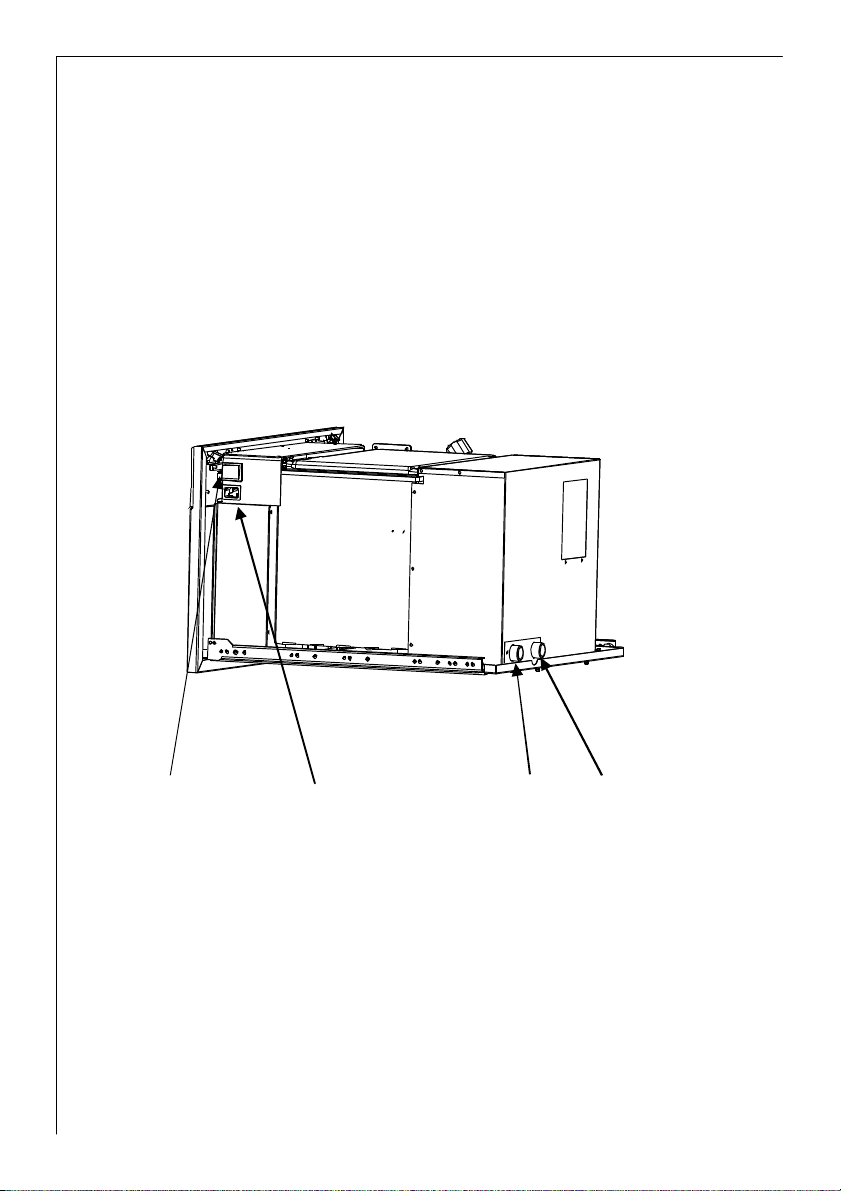
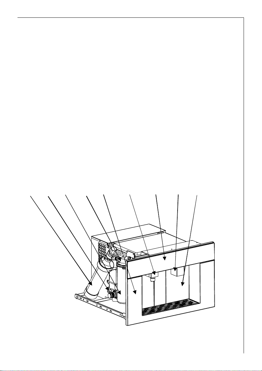
6 7 10 13
6. Main on/off switch
7. Power supply socket
8. Filter cartridge
9. CO2 bottle
10. H2O inlet
11. H2O pressure regulator with gauge
12. Filter head
13. H2O drainage
Fig. 1b
8
Page 9
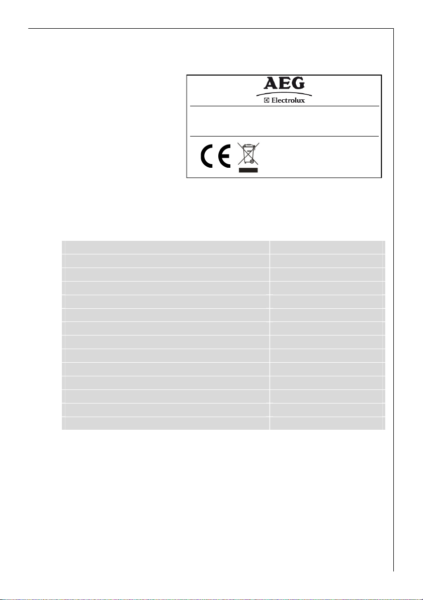
Identification plate (Fig. 2)
Should you need to contact a
technical Assistance Center,
make sure you have the serial
number handy for identification.
The serial number is on the
MODEL PNC
230 V ~ 50 Hz
MAX 190 W
TYPE SERIAL No.:
Refreshment Center
identification plate in the side of
the appliance. Extract from cabinet
MADE I N ITALY
to identify plate.
Fig. 2
Technical Characteristics
Power Supply 230-240 V
Frequency 50 Hz
Power consumption 190 W
Cold water dispense capacity 2lt @ 1 l/min.
Carbonated water dispense capacity 2lt @ 1 l/min
Dispense temperature < 13°C
Water mains pressure (water inlet) > 2.0 bar
CO2 pressure 2.5 -4 bar
Filtration 0.5 micron
Filter capacity 2840 litri
Ambient temperature conditions range 18°C-32°C
Unit dimensions L x P x H (mm) 594x554xH378
Weight 38 Kg
Refrigerant gas R134a – 60gr
942 490 XXXPWE9038-M
XXXXXXXX
9
Page 10
A
B
C
D
Installation
Warning
In order for the unit to work correctly, the Technical Characteristics specification chart on page. 6
needs to be observed.
Installation steps:
1. Refreshment unit assembly inside kitchen
2. Water mains connection
3. Water filter connection
4. Electric power supply
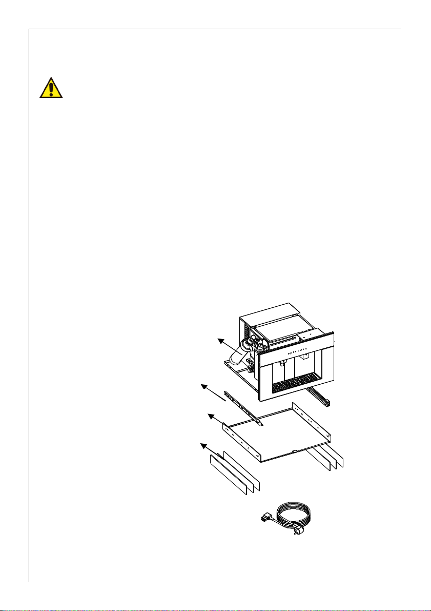
Package content
Open package and immediately check for any transport damages. During installation please handle
with care.
Inside you should find the following material:
A. Refreshment Center
B. 2 Sliding Rails
C. Mounting base plate
D. 6 spacers 2x1mm, 2x2mm,
2x3mm
Power supply cord
10
Page 11
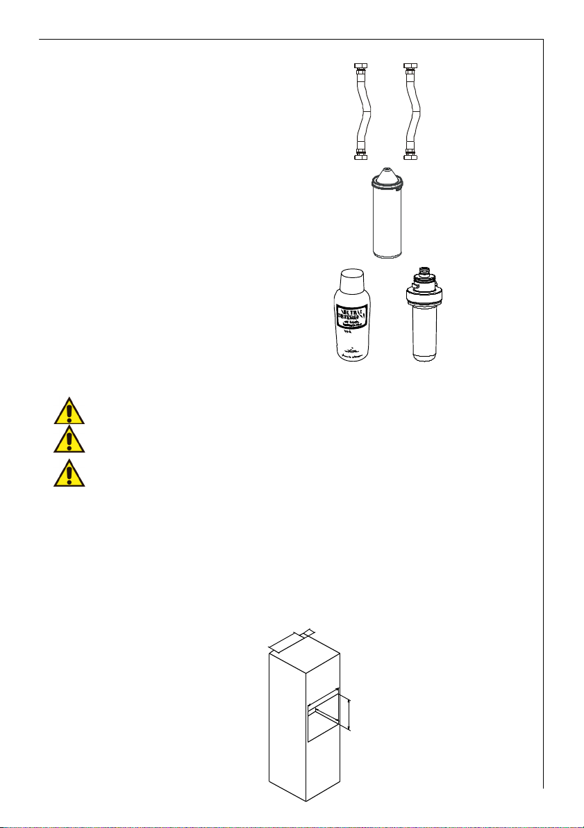
5
0
H2O inlet flexible hose and
discharge tube
Filtration Cartridge
Sanitazing cartridge and liquid
2. Unit positioning
Please install unit as far away as possible from heat sources
Please install unit higher than the water drainage in the kitchen
Please don’t install the Refreshment Center farther than 4m from the water main or please use
another water inlet and discharge tubes
The dimension requirements for the kitchen cabinet are:
1. Height (1): 360mm
2. Depth (2): 580mm
3. Width (3): 564mm
0
4
5
Fig. 3
3
2
1
11
Page 12
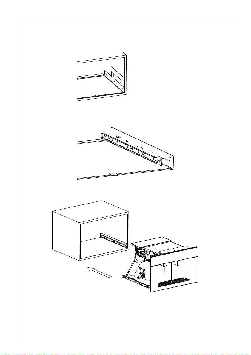
- Install the mounting base plate inside the kitchen cabinet after checking after checking
dimension requirements as shown in Fig. 3. If necessary, please use the spacers to fix the
mounting base plate to the cabinet.
- Mount the 2 sliding rails onto the base plate.
- Place the Refreshment Unit on the sliding rails.
12
Fig. 4
Page 13
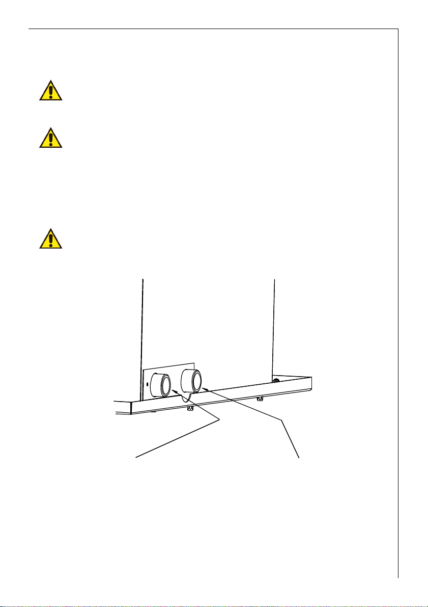
3. Water mains and siphon connection
Warning
Connect only to potable water mains.
All water mains connections should be carried out by a certified plummer.
Warning
Water mains pressure can be set through the H2O pressure regulator placed near the CO2 bottle.
Pressure should be no higher than 3.0 bars and no lower than 2.0 bars.
Complete following operations (Fig. 5):
- Connect the flexible hose to the H2O inlet on the unit. Connect water mains to flexible hose.
- Connect discharge tube to discharge barbed connection on unit and to sink siphon.
Warning
Please do not install Refreshment Center farther than 4 meters or please get longer inlet and
discharge tubes.
Fig. 5
13
Page 14

Filter cartridge
4. Install filter cartridge
Lift locking spring placed under driptray (Fig. 5a).
Pull unit from cabinet.
On the left side of the unit please find the
filter cartridge (Fig. 6).
Fig. 5a
Fig. 6
14
Remove filter plastic cap and install filter in
filter head as shown on filter instruction
booklet (Fig. 7).
Open the on/off valve placed near the filter
cartridge.
Fig. 7
Fig. 8
Page 15

Check for water leaks and make sure the CO2
bottle is tightly fixed on the CO2 pressure
regulator.
Open the pressure regulator valve and set
pressure to 3 bars on gauge.
Pressure can be increased to
4 bars to increase carbonation levels (Fig. 9).
Fig. 9
15
Page 16

5. Startup
Warning
Before plugging unit to power supply, please check for correct power supply voltage and frequency
as stated on Technical Characteristic chart (see page 9).
Fig. 10
Connect unit to 230V through supplied cord.
Electric supply circuit should conform to local laws and regulations.
Warning
The supplier declines any responsibility should any safety rule not be respected during installation.
Turn unit on through main on/off
switch on side of unit. The unit will
undergo an initialization process
which will take approx. 4 minutes.
16
Page 17

1 2 3
4
5
6
7
8
This preliminary operation will be carried out every time the unit is turned off and on through the
main on/off switch inside the cabinet. During this process the touch control panel is inactive.
After 4 minutes turn unit on through on/off button on touch control panel to activate all functions
At this point please wait approx. 3 hours before the unit reaches final working temperatures in
order to dispense cold water, carbonated water and ice-cubes. Ambient water is ready immediately.
Using the Refreshment Center
Front touch panel
1. Empty CO2 bottle led
2. On/Off switch
3. Water ambient temperature button
4. Carbonated water button
5. Cold water button
6. Ice dispense button
7. Light button On/Off
8. Exhaust filter led
17
Page 18

Dispensing
After turning appliance on through on/off
switch on touch screen, wait for cooling time
before dispensing.
Place a glass under dispense nozzle. Press
button corresponding to desired selection.
Release until desired dispense water level or
number of ice-cubes is reached. Please do not
dispense more than
1 liter of carbonated water continuously since
you might experience CO2 exhaust from
nozzle. Should that occur, please wait 1
minute and restart dispensing carbonated
water.
Dispensing is signalled by the corresponding
led.
18
In order to dispense in bottles or carafes,
please extract dispense nozzle by grabbing on
sides of nozzle and pulling forward.
Page 19

Allarms
Led indications Message
Led blinks slowly
Led is lit
Led is lit
Carbonated water
led blinks slowly
Filter is about to exhaust. 2900 liters have been dispensed.
Please change filter as described in the following chapters.
Filter is about to exhaust. 2980 liters have been dispensed.
Please change filter as described in the following chapters.
All dispense buttons disabled.
3000 liters have been reached.
Please change filter as described in the following chapters.
Carbonated water is disabled.
Time-out protection on carbonation pump activated.
To reset status please turn unit off/on on touch control panel.
CO2 bottle led on
Carbonated water is disabled.
CO2.bottle is empty.
Replace CO2 bottle to restore Carbonated water dispensing.
Please change CO2 bottle as described in the following
chapters.
19
Page 20

Leds
ambient water
ice
blink simultaneously
Leds
ambient water
cold water
carbonated water
blink simultaneously
Leds
carbonated water
ambient water
cold water
ice
blink simultaneously
All leds on
simultaneously
Ice forming bin blocked.
Turn unit on/off through main on/off switch on side of unit.
Volumetric turbine malfunctioning. Dispense functions enabled but
during dispense operation the 3 leds will blink.
Main water tank fill time-out. Please check water supply to unit. Make
sure filter shut off valve to be open.
To reset status turn unit on/off through main switch inside cabinet.
20
All dispense buttons disabled. 2 main causes:
Water present on base of unit. Possible leak.
Water level too high inside water tank. Water discharge blocked.
For the first case switch off and dry the base of the unit.
For the second case turn unit on/off through main switch inside
cabinet.
Page 21

Should alarms repeat themselves after all restart attempts, please call service assistance.
Maintenance
Before any maintenance or cleaning procedure, please switch off the appliance and disconnect it
from main by unplugging the power plug.
CO2 bottle replacement
When the CO2 led turns on, it’s necessary to replace the CO2 bottle as described below:
1. Pull appliance from cabinet
(A-Fig. 12).
Fig. 12
2. Grab the CO2 bottle and extract it from it’s
locking clip.
3. By holding the bottle fixed, turn the pressure
regulator clockwise to remove from the bottle
(fig. 13).
4. Place new bottle under the regulator and screw
counter clockwise till fully tightened.
5. Lock bottle in place and close cabinet.
Fig. 13
21
Page 22

Sanification + filtration cartridge
When the exhaust filter led turns on, it is time to replace the filter cartridge:
1. Turn unit off through main on/off switch (Fig. 11).
2. Pull unit from cabinet (Fig. 5a) and look for the valve
near the CO2 cylinder.
3. Close valve (Fig. 14).
4. Position under the water dispense nozzle a container
and dispense water to empty filter cartridge and tubes.
5. Remove the filter cartridge form its housing by rotating
counter clock-wise about a quarter turn (Fig. 15). This
will free the filter. Pull downward and remove it.
6. Fill sanitizing cartridge with 300cc of Neutral
Detergent. Insert the sanitizing cartridge on the filter
head by rotating clock-wise a quarter turn.
7. Open valve on the base of the unit (Fig. 8).
8. Dry any water from the base, that could have leaked
during this operation.
9. Position under the water dispense nozzle a container or
large cup.
10. Turn main switch. Wait approx.
5 seconds and press ”light” button until sanitizing
mode is entered. This will be shown in the display as a
moving red led through all the buttons. During this
operation, the inside of the unit will be sanitized. After
this initial cleaning cycle, the unit will dispense
automatically some cold and ambient water.
11. Shut off unit from main on/off switch.
12. Close valve on base of the unit (Fig. 14).
13. Position under the water dispense nozzle a container
and dispense water to empty sanitize cartridge and
tubes.
Fig. 14
Fig. 15
22
Page 23

14. Install new filter cartridge as shown on filter cartridge
instructions (Fig. 7) and open the valve near to the
filter cartridge.
15. Turn main on/off switch on and push appliance into
cabinet.
16. Wait 4 minutes before turning unit on through the
touch button.
17. Dispense 1 liter of cold, ambient and carbonated water
to fully rinse any sanitizing residue.
The following is a troubleshooting section for malfunctions that are not in the Alarms list above:
SYMPTOM PROBABLE CAUSE RESOLUTION
No power supply Check electric power supply Water is not dispensed
The unit has been on for over
3 hours, but no cold water
nor ice is available.
Low carbonation level
Cold water occasionally
sprays CO2 gas
Water mains inlet solenoid
valve failure
Probabile refrigerant gas
leak
Motor fan failure Call technical assistance
Compressor failure Call technical assistance
Brand new appliance Utilize for few days and check
Low CO2 pressure
Air inside carbonator
Non return valve on
carbonator dirty
Call technical assistance
Call technical assistance
carbonation
Increase CO2 pressure by
rotating knob on CO2 pressure
regulator clock-wise
Dispense few liter of
carbonated water and check
carbonation
Call technical assistance
Warning
All repairs should be carried out by authorized technicians.
23
Page 24

Environment care
The symbol on the product or on its packaging indicates that this product may not be
treated as household waste. Instead it shall be handed over to the applicable collection point for the
recycling of electrical and electronic equipment. By ensuring this product is disposed of correctly,
you will help prevent potential negative consequences for the environment and human health,
which could otherwise be caused by inappropriate waste handling of this product. For more detailed
information about recycling of this product, please contact your local city office, your household
waste disposal service or the shop where you purchased the product.
24
Page 25

Electric diagram
EV1 Ambient water electric valve
EV2 Carbonated water electric valve
EV3 Cold water electric valve
EV4 Water main electric valve
EV5 Hot gas cycle electric valve
EV6 Ice bin water charge electric valve
SW1 Microswitch work position
SW2 Microswitch discharge position
SW3 CO2 pressure switch
SW4 Main on-off double pole switch
L1-L8 Command panel leds
L9 Light bar
P1 Carbonator pump
P2 Tank discharge pump
C1 Compressor
PR1 Ice sensor probe
PR2 Dryer filter sensor probe
PR3 Flooding probe
PR4 Minimum water tank level probe
PR5 MAX Carbonator level probe
PR6 MIN Carbonator level probe
M1 Auger motor
M2 Water ice bin motor
M3 Motor fan
F1 Flow meter
T1-T6 Command panel buttons
TR1 AC-DC adapter
25
Page 26

Hydraulic diagram
26
A Water inlet
B Water drainage
C Ice cube tray
D Cold water
E Carbonated/Sparkling water
F Ambient water
G Water dispense nozzle
1 Cooling coil
2 No return valve
3 Pressure reducer
4 Valve
5 CO2 Cylinder
6 Turbine
7 Electric valve
8 Pump
9 Cartridge filter
10 Carbonator device
Page 27

Errata corrige
Package content
The package contains the mentioned material with the addition of:
- 10 screws 3.5x16 and 3 screws M4x8
- user instruction manual
Installation
Cabinet dimensions
1.The required dimensions of the cabinet space for the positioning of the unit
are:
a. Height (1): 380mm
b. Depth (2): 560mm
c. Width (3): 560mm
Unit position inside the cabinet
- After making sure that the overall size of the unit fits the cabinet space,
install the base plate (Fig.3). If necessary, please use the spacers to
adapt and fix the base plate to the cabinet space (Fig.4)
− Mount the sliding rails onto the base plate using the included 10
self-tapping screws 3.5x16 (Fig. 5)
50
5
0
0
4
5
3
2
1
Fig. 4
Fig. 5
− Place the Refreshment Center on the telescopic runners and push it
slowly until the confirming "click" sound.
Fig. 6
Page 28

Filter cartridge first installation
Lift the drip tray and pull upward the locking spring of the Refreshment
center util it unblocks (Fig.8)
Pull the bottom edge of the unit and extract the Refreshment Center
(Fig.9).
After pulling out the unit it is easier to access the left side, that contains
the filter cartridge.
Remove the capsule. Connect the filter cartridge to the filter head turning
it counter-clockwise (Fig.10)
Check for water leaks. Dry the area before installing the unit in the
opening.
Aligner installation
- After making sure that the overall size of the unit fits the cabinet space,
install the base plate (Fig.3). If necessary, please use the spacers to fix
the base plate to the cabinet space (Fig.4). Its function is to line up the
Refreshment Centre to the other possible built-in appliances in the
kitchen.
Fig. 8
Fig. 9
Fig. 10
Fig. 4
28
Page 29

CO2 bottle first installation
Disposable Bottle
The CO2 bottle can be found on the left side of the unit. Remove the
green cap and screw the pressure reducer onto the bottle until fully
tightened (Fig.11).
Open the valve on the reducer until it reaches a pressure of about 3 bar
(Fig.12).
In order to obtain a higher level of CO2 concentration, it is possible to
increase the pressure up to a maximum of about 4 bar.
Fig. 11
Rechargeable bottle
The CO2 bottle can be found on the left side of the unit. Together with
the pressure reducer is a fitting adaptor with seal ring included. The
adaptor is to be screwed onto the bottle head. For a complete assembly,
screw the pressure reducer onto the adaptor.
Open the valve on the reducer until it reaches a pressure of about 3 bar
(Fig.12).
In order to obtain a higher level of CO2 concentration, it is possible to
increase the pressure up to a maximum of about 4 bar.
Using the Refreshment Center
Warning
Use the general switch on the right side of the unit to switch it on. The on/off switch of the
front panel does not have a stand-by function; the unit is still on, but all functions are
disabled. To switch on and off the unit always use the internal general switch, even when resetting.
Fig. 12
29
Page 30

please replace the bottle
Alarms
Led indications Meaning
Filter red led blinks
slowly
Filter red led is on
Filter red led stays lit
Carbonated water led
blinks slowly
CO2 bottle led stays lit
- Ambient water
- ice cubes
leds blink
simultaneously
Filter is about to exhaust. 2,700 liters of water have been
dispensed.
Please replace the filter cartridge as described in the paragraph
"Filter replacement"
Filter exhausted. 2,800 liters of water have been dispensed.
Please replace the filter cartridge as described in the paragraph
"Filter replacement"
All dispense buttons disabled.
The limit has been reached of 2,840 liters.
To reset all dispense functions, please replace the filter cartridge
as described in the paragraph "Filter reaplacement"
Carbonated water is disabled.
A protection device on the pump activated.
To reset the unit, please turn it off and after few seconds switch
it back on using the on/off button on the control panel.
Carbonated water is disabled.
CO2 bottle is empty.
To restore carbonated water dispensing,
as described in the paragraph "CO2 bottle replacement".
Ice forming bin blocked.
To reset the unit switch it off and then back on pushing the on/off button on the
front panel.
30
Page 31

Led indications Meaning
- Ambient water
- cold water
- carbonated water
leds blink
simultaneously and fast
- carbonated water
- ambient water
- cold water
- ice cubes
leds blink
simultaneously
Volumetric turbine malfunctioning. The two possible causes are:
1. Lack of water supply from the water main;
2. Low pressure in the water inlet.
Please check the presence of water supply to the unit.
Turn unit off and then back on using the on/off switch on the front panel.
This alarm comes on only when the unit is turned on through the main on/off
switch. It means that the main tank is empty due to a lack of water supply from the
main. To reset the unit, turn off the main switch on the side of the Refreshment
Center. Check and make sure there is water supply to the unit, then turn the unit
back on.
All leds blink
simultaneously
All dispense buttons disabled. The two possible causes are:
1. Presence of water on the base of the unit;
2. The water level inside the tank is too high.
In the first case, switch off the unit and dry the base.
In the second case, reset the unit by turning it off and then back on through the
main switch on the side of the Refreshment Center.
31
Page 32

Maintenance and cleaning
Please do not touch the front control panel with wet or oily hands, in order to avoid the
malfunctioning of the touch control.
Ice melting
Do not block ice exit with any object, since it may damage the unit or prevent the correct closing of
the exit. This would cause a rise in the internal temperature with subsequent rapid ice melting
CO2 bottle replacement (for food)
When CO2 led turns on, please replace the old bottle with a new one as described below:
1. unblock the locking spring from under the drip tray (Fig. 8).
Pull out with both hands the bottom of the unit, letting the
Refreshment center slide on the telescopic runners (Fig.15).
After pulling out the unit it is easier to access the left side,
where the CO2 bottle is installed;
2. grab the bottle and extract it;
3. hold the pressure reducer and turn the bottle clockwise
(fig.16) to separate the bottle from the pressure reducer;
4. screw the new bottle to the reducer counter-clockwise till
fully tightened (Fig. 11);
5. lock the new bottle on the side of the unit.
Fig. 15
Fig. 16
32
Page 33

Sanification + filter cartridge replacement
If few days after the installation the filter replacement led turns on, please activate the sanitation
procedure to restore all functions. In such case, filter replacement is not necessary
When the “filter” led turns on, it is necessary to replace the cartridge filter as described below:
1. unblock the locking spring (Fig.8) and pull out the Refreshment
Center unit (Fig.15);
2. turn off the unit through the main on/off switch;
3. see filter cartridge on the left (Fig. 1a);
4. rotate the exhausted cartridge clockwise about a quarter of a
turn to remove it from the head (fig.17) and extract it avoiding
water spillage;
5. fill the sanification cartridge with “Neutral Detergent”. Insert
the sanitizing cartridge on the filter head by rotating it
counter-clockwise about a quarter turn (Fig.18);
6. in case of water spillage, dry the base and make sure there
are no leaks;
7. place a big cup under the water dispense nozzle (the
appliance will deliver round 250ml of water);
Fig. 17
8. turn on the main switch pushing at the same time the light-
switching button for approximately 5". Press the "light"
button two more times, each time for 5". This will activate
the sanitizing mode, displayed as a red led moving through
all the buttons of the front panel; during this operation, the
inner tank will be sanitized. After this initial cleaning cycle,
the unit will automatically dispense some cold and ambient
water mixed with the sanitizing solution;
Fig. 18
Fig. 19
33
Page 34

9. turn off the unit through the main switch;
10. remove the sanification cartridge (Fig.19) and connect the
new filter cartridge to the head as shown on filter cartridge
instructions (Fig.20);
11. turn on the main switch and push the Refreshment Center
into the cabinet until the locking spring clicks (Fig.21);
12. wait 4 minutes before activating the unit pushing the on/off
button on the control panel;
13. dispense 1 liter of cold, carbonated and ambient water to
fully rinse the lines and eliminate any residual of sanitizing
solution.
Warning
During the sanitizing procedure please do not dispense carbonated water.
Fig. 20
Fig. 21
34
Page 35

35
Page 36

Guarantee/Customer Service
Standard guarantee conditions
We, AEG-Electrolux, undertake that if within 12 months of the date of the purchase this AEGElectrolux appliance or any part thereof is proved to be defective by reason only of faulty
workmanship or materials, we will, at our option repair or replace the same FREE OF CHARGE for
labour, materials or carriage on condition that:
- The appliance has been correctly installed and used only on the electricity supply stated on
the rating plate.
- The appliance has been used for normal domestic purposes only, and in accordance with the
manufacturer’s instructions.
- The appliance has not been serviced, maintained, repaired, taken apart or tampered with by
any person not authorised by us.
- Electrolux Service Force Centre must undertake all service work under this guarantee
- Any appliance or defective part replaced shall become the Company’s property.
- This guarantee is in addition to your statutory and other legal rights.
Exclusions
- Damage or calls resulting from transportation, improper use or neglect, the replacement of
any light bulbs or removable parts of glass or plastic.
- Costs incurred for calls to put right an appliance which is improperly installed or calls to
appliances outside the United Kingdom.
- Appliances found to be in use within a commercial environment, plus those which are subject
to rental agreements.
- Products of Electrolux manufacturer that are not marketed by Electrolux
Page 37

Service and Spare Parts
In the event of your appliance requiring
service, or if you wish to
purchase spare parts, please contact your local
Service Force Centre by
telephoning
0870 5 929 929
Your telephone call will be automatically
routed to the Service Force
Centre covering your postcode area.
For the address of your local Service Force
Centre and further information about Service
Force, please visit the website at
www.serviceforce.co.uk
Before calling out an engineer, please ensure
you have read the details
under the heading “Something not working”.
When you contact the Service Force Centre you
will need to give the
following details:
1. Your name, address and postcode.
2. Your telephone number.
3. Clear concise details of the fault.
4. The model and Serial number of the appliance (found on the rating plate).
5. The purchase date.
Please note a valid purchase receipt or
guarantee documentation is required for in
guarantee service calls.
Customer Care
For general enquiries concerning your
Electrolux appliance, or for
further information on Electrolux products
please contact our Customer Care Department by
letter or telephone at the address below or
visit our website at www.electrolux.co.uk
Customer Care Department
Electrolux Major Appliances
37
Page 38

Addington Way
Luton
Bedfordshire, LU4 9QQ
Tel: 08705 350 350 (*)
(*) Calls may be recorded for training purposes
38
Page 39

Belgien
Alcalá de Henares Ma
drid
LU4 9QQ
European Guarantee
This appliance is guaranteed by Electrolux in
each of the countries listed at the back of
this user manual, for the period specified in
the appliance guarantee or otherwise by law. If
you move from one of these countries to another
of the countries listed below the appliance
guarantee will move with you subject to the
following qualifications:-
- The appliance guarantee starts from the date you first purchased the appliance which will be
evidenced by production of a valid purchase document issued by the seller of the appliance.
- The appliance guarantee is for the same period and to the same extent for labour and parts as
exists in your new country of residence for this particular model or range of appliances.
- The appliance guarantee is personal to the original purchaser of the appliance and cannot be
transferred to another user.
- The appliance is installed and used in accordance with instructions issued by Electrolux and is
only used within the home, i.e. is not used for commercial purposes.
- The appliance is installed in accordance with all relevant regulations in force within your new
country of residence.
The provisions of this European Guarantee do
not affect any of the rights granted to you by
law.
www.electrolux.com
Albania +35 5 4 261 450 Rr. Pjeter Bogdani Nr. 7 Tirane
Belgique/België/
Èeská republika +420 2 61 12 61 12 Budìjovická 3, Praha 4, 140 21
Danmark +45 70 11 74 00 Sjællandsgade 2, 7000 Fredericia
Deutschland +49 180 32 26 622 Muggenhofer Str. 135, 90429 Nürnberg
Eesti +37 2 66 50 030 Mustamäe tee 24, 10621 Tallinn
España +34 902 11 63 88
France www.electrolux.fr
Great Britain +44 8705 929 929
+32 2 363 04 44 Bergensesteenweg 719, 1502 Lembeek
Carretera M-300, Km. 29,900
Addington Way, Luton, Bedfordshire
39
Page 40

33080 Porcia (PN)
518 Paço de Arcos
Svizzera
Stockholm
Hellas +30 23 10 56 19 70 4 Limnou Str., 54627 Thessaloniki
Hrvatska +385 1 63 23 338 Slavonska avenija 3, 10000 Zagreb
Ireland +353 1 40 90 75 Long Mile Road Dublin 12
Italia +39 (0) 434 558500
C.so Lino Zanussi, 26 -
Latvija +37 17 84 59 34 Kr. Barona iela 130/2, LV-1012, Riga
Lietuva +370 5 2780609 Verkių 29, LT_09108 Vilnius
Luxembourg +35 2 42 43 13 01 Rue de Bitbourg, 7, L-1273 Hamm
Magyarország +36 1 252 1773
H-1142 Budapest XIV,
Erzsébet királyné útja 87
Nederland +31 17 24 68 300 Vennootsweg 1, 2404 CG - Alphen aan den Rijn
Norge +47 81 5 30 222 Risløkkvn. 2 , 0508 Oslo
Österreich +43 18 66 400 Herziggasse 9, 1230 Wien
Polska +48 22 43 47 300 ul. Kolejowa 5/7, Warsaw
Portugal +35 12 14 40 39 39
Quinta da Fonte - Edificio Gonçalves Zarco - Q 352774 -
40
Romania +40 21 451 20 30 Str. Garii Progresului 2, S4, 040671 RO
Schweiz/Suisse/
Slovenija +38 61 24 25 731
Slovensko +421 2 43 33 43 22
+41 62 88 99 111 Industriestrasse 10, CH-5506 Mägenwil
Electrolux Ljubljana, d.o.o.Tržaška 132,
1000 Ljubljana
Electrolux Slovakia s.r.o., Electrolux
Domáce spotrebièe SK, Seberíniho 1,
821 03 Bratislava
Suomi +35 8 26 22 33 00 Konepajanranta 4, 28100 Pori
Sverige +46 (0)771 76 76 76
Türkiye +90 21 22 93 10 25 Tarlabaþý caddesi no : 35 TaksimIstanbul
Pоссия +7 495 9377837
Electrolux Service, S:t Göransgatan 143,S-105 45
129090 Мосва, Олимпийский проспект,
16, БЦ, „Олимпик“
Page 41

41
Page 42

42
Page 43

43
Page 44

From the Electrolux Group. The world´s No.1 choice.
The Electrolux Group is the world´s largest producer of powered appliances for kitchen,
cleaning and outdoor use. More than 55 million Electrolux Group products (such as
refrigerators, cookers, washing machines, vacuum cleaners, chain saws and lawn mowers)
are sold each year to a value of approx. USD 14 billion in more than 150 countries around the
world.
Prokom
Gesellschaft für Gebrauchsanweisungen mbH
Muggenhofer Straße 135
D-90429 Nürnberg
http://www.aeg-electrolux.de
© Copyright by AEG
8946 Subject to change without notice
 Loading...