

Page 1
PWE3810-M
User Manual Refreshment Centre
Page 2
2 Contents
Contents
Safety information 2
Appliance description 4
Main components 4
Rating plate 5
Technical specifications 6
Package content 6
Installation 7
Unit positioning 7
Unit connection 12
Usage 16
Maintenance and cleaning 17
Signals for users 23
What to do if... 24
Environment concerns 25
Safety information
Fundamental safety warni ngs
War n ing The appliance must be earthed in compliance with legislation. Electrical and Water
connection must be carried out by qualified technicians following the instructions
War n ing Keep all packaging (plastic bags, polystyrene foam) away from children
War n ing The appliance is not to be used by people (including children) with reduced physical,
sensory or mental capabilities, or lack of experience and knowledge, unless they have been given
supervision or instruction concerning use of the appliance by a person responsible for their safety
War n ing In order for children not to play with the appliance, a close supervision is required
War n ing Do not grasp the appliance when it is out of the cabinet. Do not rest recipients
containing liquids or inflammable or corrosive materials on top of the appliance
War n ing Do not use the appliance when extracted, except for installation, maintenance and “What
to to do if...” sections. For any other operation make sure the appliance is inactive
War n ing Water leakage will occur when the discharge tap is open
Instructions
Read these instructions carefully before using the appliance.
• Keep the instructions
• Failure to respect these instructions may result in injuries or in damages to the appliance
The manufacturer is not liable for damage deriving from failure to respect these instructions
Use original or manufacturer recommended accessories and spare parts only.
Page 3

Safety information
3
Designated use
War n ing This is a household appliance only
It is not intended to be used in:
• Staff kitchen areas in shops
• Offices and other working environments
• Farm houses
• By clients in hotels, motels, and other residential type of environments
• Bed and breakfast type of environments
The appliance is designed and made to supply water and ice. Other uses are considered improper. This
appliance is not suitable for commercial use. The manufacturer is not liable for damage deriving from
improper use of the appliance.
Electrical safety
War n ing The appliance must be earthed in compliance with legislation. Electrical connection
must be carried out by qualified technicians following the instructions
War n ing This is an electrical appliance, it is therefore important to respect the following safety
warnings:
• Never touch the plug with wet hands.
• Make sure the socket is freely accessible at all times, enabling the appliance to be unplugged when
necessary.
• If the appliance is faulty, do not attempt to repair it. Turn it off using the power switch, unplug from
the main socket and contact your local Service Force Centre.
Check that the main power supply voltage corresponds to the value indicated on the rating plate on the
left side of the appliance. Connect the appliance to an efficiently earthed and correctly installed socket.
If the power socket does not match the plug on the appliance, have the socket replaced with a suitable
type by a qualified professional. Do not use multiple sockets or extensions.
During installa tion and Use
War n ing Move the appliance carefully in order not to damage components of the refrigeration
circuit and to avoid gas leaks
War n ing Avoid prolonged exposure of the appliance to direct sunlight
War n ing When installing the appliance do not over bend hoses
After removing the packaging, make sure the product is complete and undamaged and that all
components are present.
Do not use the appliance if it is visibly damaged. Contact your local Service Force Centre.
• Installation must be carried out by qualified professional in compliance with legislation in force in
the country of installation.
• The packing elements (plastic bags, polystyrene foam, etc.) should be kept out of reach of children.
• Do not install the appliance in rooms where the temperature may raise up to 35°C or above.
Page 4
4 Safety information
Surface treatment
War n ing Before performing any washing operation, the appliance must be switched off and
unplugged from the power supply
War n ing Do not use solvents or abrasive detergents.
A soft damp cloth will suffice
Environmental protectio n
Electrical appliances must not be disposed of as household waste. Appliances with this symbol are
covered by European Directive 2002/96/EC. All unused electric and electronic appliances must be
disposed of separately from household waste and taken to country-authorised special centres.
Appliance description
Refreshment Centre is a household appliance that refrigerates, purifies and carbonates the water from
the mains and makes ice shards.
Its two nozzles dispense:
• Ambient water
• Cold sparkling water
• Cold still water
• Ice shards
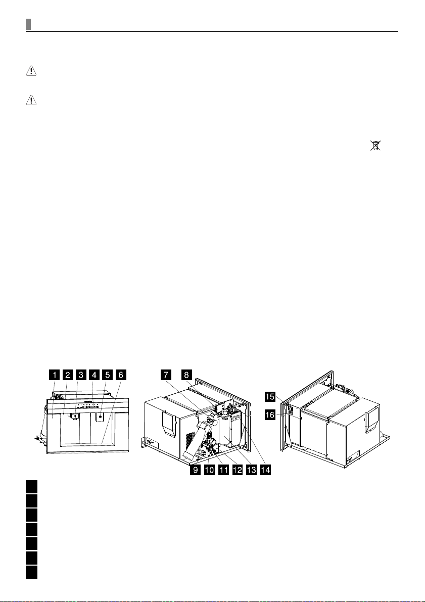
Main components
Refreshment Centre's main com p o n e n t s
1 Stainless steel front frame
2 Water discharge nozzle
3 Water dispense nozzle
4 Control panel (icons and LEDs)
5 Ice dispensing nozzle
6 Drip tray
7 CO pressure reducer₂
Page 5
Main components
5
8 Filter head
9 CO bottle₂
10Water pressure reducer
11Water discharge tap
12Water inlet
13Filter cartridge
14Rating plate
15Power switch
16Power supply socket
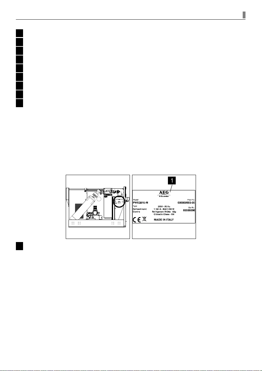
Rating plate
Under no circumstances should you attempt to repair the machine yourself. Repair carried out by
inexperienced people could cause injury or serious malfunctioning. Contact your local Service Force
Centre. Always insist on genuine spare parts.
When contacting your local Service Force Centre, you will be asked to give the data and the feature
information of the Refreshment Centre, to be found in the rating plate on the left side of the appliance.
1 Rating plate
Page 6
6 Technical specifications
Technical specifications
Tec h nic al s peci fica tion s
Power Supply Voltage 230-240 V
Frequency 50 Hz
Power consumption MAX 260 W
Cold still water dispense capacity 2lt @ 1 l/min.
Cold sparkling water dispense capacity 2lt @ 1 l/min.
Ice shards 200g / 2h
Dispense temperature < 13°C
Water mains pressure (water inlet) > 0.2 MPa (> 2 bar), < 0.6 MPa (< 6 bar)
CO pressure₂ > 0.25 MPa (> 2.5 bar), < 0.40 MPa (< 4 bar)
Filtration 0.5 micron
Filter capacity 2840 litres
Climatic class SN (> +10°C, < +32°C)
Dimensions W x D x H 594x578x378 mm
Weight 34 Kg
Refrigerant gas R134a – 62gr
Package content
After removing the packaging, make sure the product is complete and undamaged and that all
components are present.
Move it carefully avoiding shocks or downfalls that may damage the refrigeration circuit.
The package contains the following material:
• Refreshment Centre
• 2 sliding rails
• Spacers 2x1mm, 2x2mm, 2x3mm
• 2 support brackets
• Frontal spacer
• Water inlet hose
• Filter cartridge
• Plastic hose for water tank discharge
• Rechargeable CO bottle with adapting junction or disposable CO bottle₂ ₂
• CO pressure reducer₂
• Cleaning cartridge
• Neutral detergent
• Safety strip to fix CO bottle₂
• 8 4.5x16mm self threading screws for support brackets
• 4 M6x12 circular spacers
• 3 M4x12 screws for frontal spacer
• 2 M4x12 screws to fix the Refreshment Centre to sliding rails
Page 7
Installation
7
Installation
War n ing It is necessary to install the appliance properly. The power supply and water connection
data in the Technical Specifications chart must be observed
Unit positioning
• Check for minimum requirements
• Spacers installation
• Support brackets installation
• Sliding rails installation
• Positioning in the kitchen cabinet
• Frontal spacer installation
Unit connection
• Secure water discharge tap
• Pressure reducer first installation
• CO bottle first installation₂
• Water mains connection
• Filter cartridge first installation
• Electrical connection
Unit positioning
War n ing The installation of the product should be made above the level of the water mains
War n ing To ensure proper ventilation, leave a gap at the bottom of the cabinet (see
measurements in the drawing)
War n ing The installation of the Refreshment Centre in direct conjunction with an oven might
cause performance reduction
War n ing Safety cut-out devices must be fixed properly so that they cannot be removed without
tools
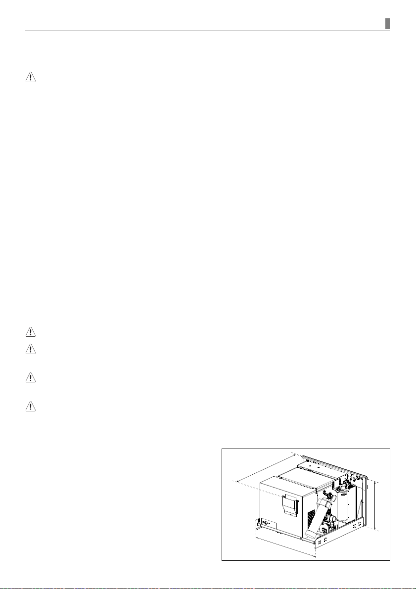
Check for minimum requi r e m e n t s
Verify the minimum measurements required for a
correct installation of the appliance.
5
6
0
m
m
3
7
8
m
m
m
a
x
5
5
8
m
m
m
a
x
Page 8
8 Unit positioning
The Refreshment Centre must be installed in a cabinet
and the cabinet must be firmly fixed to the wall.
Leave room behind the appliance as described in these
instructions to avoid overheating.
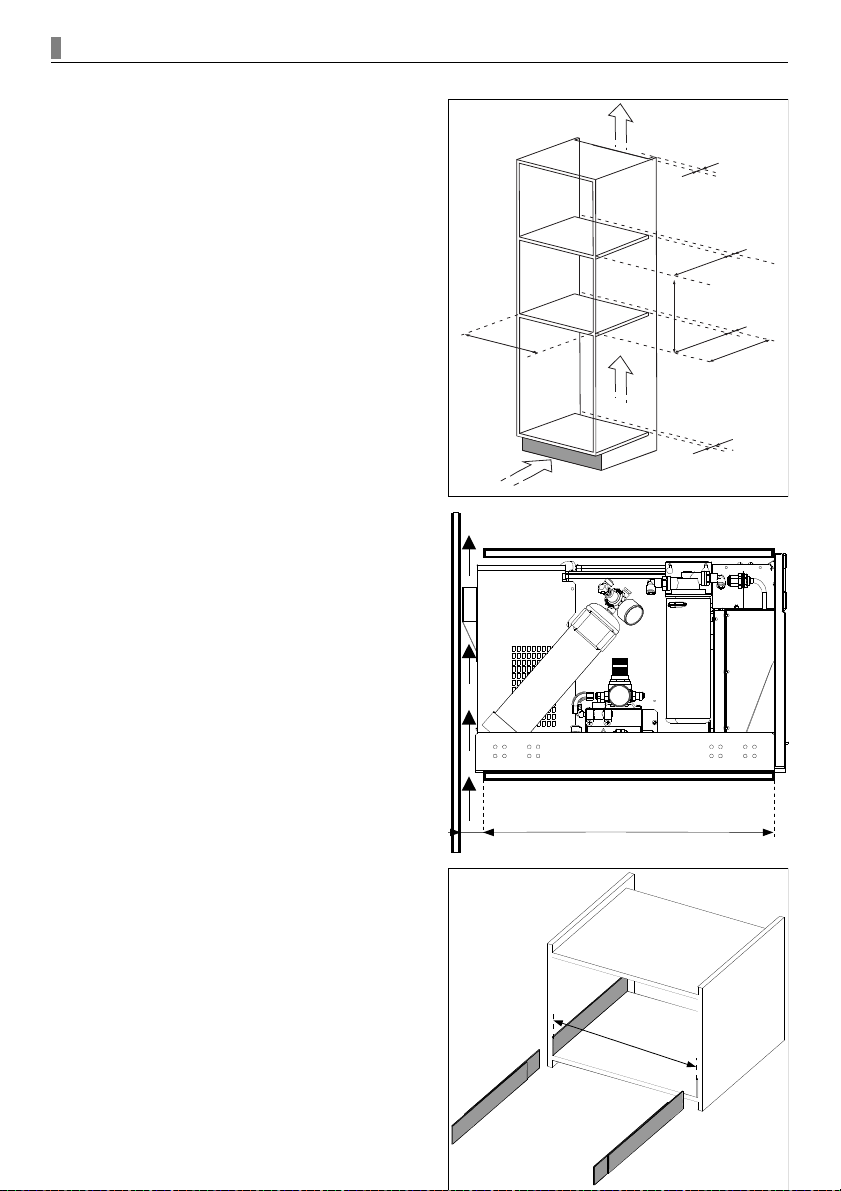
Spacers installa t ion
To ensure a smooth installation of the appliance, you need the same internal width as shown in the
picture below. Use the provided spacers to adjust internal width.
For their correct positioning, place the spacers directly in contact with both the shelf and the side of the
cabinet.
Support brackets installa t i o n
After positioning the spacers, place the two provided support brackets.
5
2
0
m
m
5
6
0
+
8
m
m
5
6
0
m
m
m
i
n
225 cm
q min
380 + 2 mm
4
0
m
m
4
0
m
m
4
0
m
m
5
2
0
m
m
4
0
m
m
5
6
0
m
m
520 m
m m
in
40 m
m m
in
Page 9
Unit positioning
9
For a correct installation, take the single support
bracket and place it directly in contact with both the
shelf of the cabinet and the spacer if previously used.
Otherwise the bracket will be in direct contact with both
shelf and side of the cabinet.
After this first phase, align the support brackets to be flush with the front of the cabinet.
Use the upper holes to correctly mount the appliance at
the right height.
War n ing Mount the screws perpendicularly to the cabinet in order to guarantee the correct
extraction of the sliding rails
A pilot hole is recommended for an easier assembly.
Extract the screws to continue the mounting.
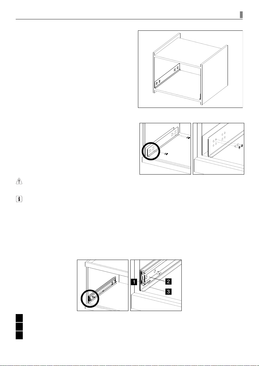
Sliding rails installa t i o n
Position each rail on the side of the cabinet. Please note that there is a specific sliding rail for each side
of the cabinet.
Each sliding rail should be flush with the support brackets, with spacers when present and with the front
of the cabinet.
1 Spacer
2 Sliding rail
3 Support bracket
Page 10

10 Unit positioning
Pull out the sliding rail until the cabinet underneath
becomes visible.
Fix the sliding rail, the support bracket and the spacer
with the provided self-threading screws 4.5x16.
When extracting the sliding rails, only one of the frontal holes will become visible. After mounting
the corresponding screw, move the rail again to see the second hole and mount the corresponding
screw.
Positioning in the kitchen ca b i n e t
Pull the sliding rails completely out, and place the Refreshment Centre on them making sure that the
conical pivots match the holes on the base.
Fix the Refreshment Centre on the bottom side of the
sliding rails with the 2 provided M4x12 screws.
Push back the Refreshment Centre, until it is locked into position.
Check aesthetic alignment with the cabinet and use the provided circular spacers M6x12 for final
adjustment.
Frontal spacer installa t i o n
When included in the package, and if necessary, fix the frontal spacer with the 3 supplied M4x12
screws.
Page 11

Unit positioning
11
1 Frontal spacer
2 M4x12 screws
Unit connection
All the operations below require the appliance to be extracted from cabinet.
Remove the grid of the drip tray to easily pull out the Refreshment Centre. After extracting the
appliance, place the grid back in its original position.
Electrical connection
War n ing Before starting the plug-in, make sure voltage and frequency match the related
information on the rating plate and on the technical specifications table.
War n ing Make sure the main switch is in off position
Connect the appliance to the socket using the supplied cord.
When necessary, extract momentarily the power cord from the safety clip to make the connection to the
power socket easier.
Fix the supplied cord to the clip on the right side of appliance.
Page 12

12 Unit connection
1 230V AC Socket
2 Clip to fix cord
Secure water discharge tap
War n ing Water leakage will occur when the discharge tap is open
War n ing Close the water discharge tap if open.
A red safety screw prevents the accidental opening of the tap.
During regular appliance operation, when not otherwise indicated, the tap shall be closed and the screw
inserted.
1 Water discharge tap
2 Safety screw
Water mains connection
War n ing Provided inlet hose can reach a maximum distance of 4 meters from the water mains. In
alternative, extra long tubes need to be used
War n ing It is necessary to place a tap between the water mains and the water inlet hose
War n ing Connect only to potable cold water mains
War n ing All water mains connections must be carried out by a certified plumber
War n ing Use only the new hose-sets included in the package
War n ing Do not reuse old hose-sets
Screw the hose to water inlet rotating it clockwise, then connect the hose to the water mains.
Page 13

Unit connection
13
1 Water inlet 3/4”
Filter cartridge firs t i n s t a l l a t i o n
War n ing Make sure there are no water leaks
War n ing Dry well the base of the appliance before installing it into the cabinet
The head of the filter cartridge is on the left side of the appliance.
Remove the cap from the filter cartridge, hold the filter head tight and insert the new filter cartridge in
the head by pushing it up and rotating it counter-clockwise.
1 Filter head
2 Filter cartridge
Pressure reducer first installation
War n ing Do not open the pressure reducer during unit connection
1 CO tube₂
2 CO fitting₂
Pull out the CO -labeled tube and its fitting placed on the left side of the appliance and then insert the₂
fitting in the CO pressure reducer. ₂
Page 14

14 Unit connection
CO b ottle first install a t i on₂
War n ing While screwing on the new CO bottle, CO leaks might occur₂ ₂
The CO bottle is placed on the left side of the appliance.₂
The appliance can operate with both disposable and rechargeable CO bottles.₂
With disposable CO bottles₂
1. Remove the plastic cap
2. Screw the bottle rotating it clockwise on the pressure reducer
With rechargeable CO bottles, an adapting junction is provided with the pressure reducer.₂
1. Screw the adapting junction rotating it clockwise on the pressure reducer
2. Screw the bottle rotating it clockwise on the adapting junction
Make sure the CO bottle is tightly fixed.₂
1. Lock the bottle in the bottle holder on the left side of the appliance
2. Fix the holder with the provided safety strip
Page 15

Usage
15
Usage
Front touch control panel
War n ing To prevent damages to the touch control panel, do not touch it with wet or oily hands
1 Empty CO bottle LED₂
2 Power LED (to be used also during water tank draining)
3 Ambient water LED
4 Cold sparkling water LED
5 Cold still water LED
6 Ice shards LED
7 Light LED
8 Filter LED
First Start-up
War n ing Dispense 3 litres of cold still water and 1 litre of cold sparkling water to rinse out well
the water coils
Turn on the appliance using the power switch placed on the right side of the appliance.
The power LED will start flashing.
When the power LED stops flashing, the touch control panel becomes active.
When using the Refreshment Centre for the first time you need to wait 5 hours before the appliance
provides full operating results.
During this period of time the appliance is working but with limited performance.
The above procedure needs to be followed also after extended inactive period of time.
Regulate water inlet press u r e
War n ing The pressure reducer must be opened only when the installation process is complete
and the appliance is switched on
Page 16

16 Usage
1 Water plastic knob
2 Water pressure gauge
Make sure that the tap between the water mains and the flexible hose is open.
After any pressure regulation, verify the new adjusted level by dispensing a little water.
Pressure has to be regulated between 2 and 3 bar operating on the plastic knob.
To regulate the pressure, pull up the water plastic knob.
While dispensing ambient water: for pressure increase rotate the knob clockwise, for pressure decrease
rotate it counter-clockwise.
Once the regulation has been made, push the knob back to its security position.
Regulate CO p r e s s u r e₂
War n ing The pressure reducer must be opened only when the connection process is complete
and the appliance is powered up
War n ing When changing CO pressure, the adjusted sparkling level will be reached after₂
dispensing 0.5 litres of cold sparkling water
War n ing CO p₂ ressure can be adjusted to a maximum of 4 bar
1 CO p₂ lastic knob
2 CO pressure ₂ gauge
CO pressure can be adjusted using the pressure reducer placed on the CO bottle.₂ ₂
Pressure has to be regulated 0.5 bar above inlet water value operating on the CO plastic knob.₂
For pressure increase rotate the knob clockwise, for pressure decrease rotate it counter-clockwise.
Dispensing during firs t s t a r t - u p
During first start-up ambient water is immediately ready.
The first ice shards will be ready after 90 minutes.
The ideal temperature for cold water will be reached after 2.5 hours.
The ice tank will be fully loaded after 5 hours.
Page 17

Usage
17
Dispensing during norm a l usage
War n ing Do not insert any object in the ice shards nozzle. This may damage the section with
consequent ice melting
In order to fill a big bottle or jug, carefully pull out the water dispense nozzle.
Place a glass on the drip tray, then select the desired beverage or the ice shards. Press the icon until
the desired amount has been dispensed.
Dispensing is indicated by the LED corresponding to the
pressed icon.
Dispensing from water nozzle is delayed to prevent accidental leakage.
The appliance can dispense 2 litres of cold still or cold sparkling water in 2 hours.
The water coolness level may vary if the dispensing time recommendations are not followed.
If the ice has been entirely dispensed, fresh ice shards will be available after approximately 40 minutes.
The ice tank will be fully loaded after 2.5 hours.
Illumination of the Refre s h m e n t C e n t r e
For a more comfortable dispensing process, press the light LED of the control panel and switch on the
central ambient light.
Maintenance and cleaning
War n ing If the appliance remains switched off for over 8 hours it is necessary to drain the water
tank
War n ing A monthly drainage of the water tank is needed to guarantee the correct quality level
War n ing Carry out a cleaning of the appliance every six months to ensure the correct quality level
War n ing Use food grade CO bottle₂
Drainage of the drip tra y
To prevent water leakage, keep the drip tray clean and dry.
Page 18

18 Maintenance and cleaning
Drainage of the water tank
War n ing If you had to stop pressing the power icon, please press it again and keep it pressed in
order to complete the step
War n ing After the procedure always remember to close the water discharge tap to avoid water
leakage
1. Dispense all the available ice shards
2. Remove the grid of the drip tray to easily pull out the Refreshment Centre. After extracting the
appliance, place the grid back in its original position
3. Connect the plastic hose to the discharge water nozzle
4. Place a big container underneath the plastic hose or put the hose in a sink
5. Press the power icon until power LED starts flashing
6. Remove the safety screw and open the water discharge tap
7. Press the power icon again and keep it pressed until the power LED stops flashing
8. Close the water discharge tap and reinsert the safety screw
9. Restart the appliance using the power switch
10. Push back the appliance until it is locked into position
Food grade CO b o t t l e replacement₂
War n ing While screwing on the new CO bottle, CO leaks might occur₂ ₂
Page 19

Maintenance and cleaning
19
1. Remove the grid of the drip tray to easily pull out the Refreshment Centre. After extracting the
appliance, place the grid back in its original position
2. Remove the safety strip of the CO holder to extract the used bottle₂
3. Hold the pressure reducer and turn the CO bottle clockwise₂
4. Screw the new bottle, counter-clockwise, into the pressure reducer
5. Secure the new CO bottle to its holder and fix it with the provided safety strip₂
6. Push back the appliance until it is locked into position
Filter cartridge repla c e m e n t
War n ing In case of water leakage dry the base carefully
War n ing Lay a cloth under the filter cartridge to prevent the base from getting wet
1. Remove the grid of the drip tray to easily pull out the Refreshment Centre. After extracting the
appliance, place the grid back in its original position
2. Turn off the appliance using the power switch
Water may come out from the filter cartridge, therefore place a cloth on the filter head and
cartridge to prevent the cabinet from getting wet.
If there is water on the base, dry it carefully.
Page 20

20 Maintenance and cleaning
3. Rotate the used filter cartridge clockwise and pull it down to extract it
4. Insert the new filter cartridge in the filter head by pushing it up and rotating it counter-clockwise
5. Turn on the power switch
6. Immediately press the ambient water icon and keep it pressed until LEDs start scanning.
Wait for all LEDs to turn off before proceeding with the next step
If the power LED becomes steady, please repeat the last two steps until LEDs start scanning.
7. Restart the appliance using the power switch
8. Push back the appliance until it is locked into position
9. Dispense 3 litres of cold still water
10. Dispense 1 litre of cold sparkling water
Cleaning of the inlet filter
1 Water inlet and inlet filter housing
Carry out this procedure on a yearly basis.
1. Close the water mains
2. Dispense ambient water until it stops coming out
3. Remove the grid of the drip tray to easily pull out the Refreshment Centre. After extracting the
appliance, place the grid back in its original position
4. Rotate the filter cartridge clockwise and pull it down to extract it
5. Take out the water inlet hose
Page 21

Maintenance and cleaning
21
6. Extract the inlet filter with rounded-jaw pliers
7. Clean the inlet filter
8. Insert the inlet filter and place it in its original position
9. Insert the water inlet hose and place it in its original position
10. Insert the filter cartridge in the filter head by pushing it up and rotating it counter-clockwise
11. Push back the appliance until it is locked into position
12. Open the water mains
Cleaning
War n ing Do not dispense cold sparkling water during the cleaning procedure
War n ing After the procedure always remember to close the water discharge tap to avoid water
leakage
War n ing Remove the water dispensed during cleaning process
War n ing In case of water leakage dry the base carefully
War n ing Lay a cloth under the filter cartridge to prevent the base from getting wet
During cleaning process two kinds of LED signals are shown:
• Flashing power LED:
waiting for user input
• Scanning LEDs, from power to light LED:
working on cleaning, wait for the power LED to flash
1. Dispense all the ice shards
2. Remove the grid of the drip tray to easily pull out the Refreshment Centre. After extracting the
appliance, place the grid back in its original position
3. Turn off the appliance using the power switch
Page 22

22 Maintenance and cleaning
Water may come out from the filter cartridge, therefore place a cloth on the filter head and
cartridge to prevent the cabinet from getting wet.
If there is water on the base, dry it carefully.
4. Rotate the filter cartridge clockwise and pull it down to extract it
5. Open the cleaning cartridge and fill it with “Neutral Detergent”
6. Hold the cleaning cartridge from the upper larger side and insert it in the filter head by pushing it up
and rotating it counter-clockwise
7. Connect the plastic hose to the discharge water nozzle
8. Place a big container underneath the plastic hose or put the hose in a sink
9. Place a cup under the water dispense nozzle
10. Remove the safety screw and open the water discharge tap
11. Turn on the power switch
12. Immediately press the light icon and keep it pressed until LEDs start scanning
If the power LED became steady, please repeat the two last steps until LEDs start scanning
13. Wait for the power LED to flash, then press the power icon until the LEDs start scanning again
Some water will be dispensed from the water dispenser automatically
14. Wait for the power LED to flash, then remove the cleaning cartridge
Water may come out from the cleaning cartridge.
If there is water on the base, dry it carefully.
15. Insert the filter cartridge in the filter head by pushing it up and rotating it counter-clockwise
16. Press the power icon until LEDs start scanning again
17. Wait for the power LED to flash, then press the power icon until all LEDs start scanning.
Wait for all LEDs to turn off before proceeding with the next step
Some water will be dispensed from the water dispenser automatically
18. Close the water discharge tap and reinsert the safety screw
19. Restart the appliance using the power switch
Page 23

Maintenance and cleaning
23
20. Push back the appliance until it is locked into position
21. Dispense 3 litres of cold still water
22. Dispense 1 litre of cold sparkling water
23. Dispense all ice shards
Signals for users
Signals for users on the fr o n t p a n e l
LED ty pe Mes sage
Power LED
Flashing LED:
• Appliance preparation to start-up
Steady LED:
• Power on signal
Filter LED
Flashing LED:
• There are 40 litres left before a new filter cartridge is
needed
Steady LED:
• Change the filter cartridge, there are 5 litres left before
safety lock of the appliance
• Check “Maintenance and cleaning” chapter
CO bottle LED ₂
Steady LED:
• Cold sparkling water is disabled
• CO bottle is empty or missing₂
• Check “Maintenance and cleaning” chapter
Six LEDs alarm
6 flashing LEDs (except filter and CO₂ bottle)
Check “What to do if...” chapter
Page 24

24 What to do if...
What to do if...
Warning All repairs should be carried out by authorised technicians
Pro blem Ca use Res olut ion
Cold sparkling water sprays CO gas₂ Carbonator limit reached Stop the dispensing and wait 20
seconds, then start dispensing again
Water is not dispensed No water supply Check water supply
Inlet water low pressure Check water inlet pressure
Small ice shards No water supply Check water supply
Low pressure of inlet water Check water inlet pressure
Low carbonation level Low CO pressure₂ Check CO pressure₂
Brand new appliance Use for 1 week
After a week Call technical assistance
No cold water, no shards available 3
hours after starting the appliance
Cooling system Call technical assistance
Cold still water sprays CO gas₂ Carbonating system Call technical assistance
Six LEDs alarm trouble s h o o t i n g
All operations below require for the appliance to be switched on and extracted from cabinet.
Pull out the Refreshment Centre and proceed as follows
• Check water supply
• Check water inlet pressure
• Check CO pressure₂
• Water leakage check
• Cold restart
If none of the procedures turns off the alarm or resolve your problem, close the inlet water and call the
Assistance.
Check water supply
Check if the tap between the water mains and the water inlet hose is open or water is coming out from
other taps in the house.
When water comes out and the water mains work properly, proceed with the step Check water inlet
pressure.
If your water mains connection does not work properly, please have it checked.
Check water inlet pressure
War n ing It is recommended to check the CO pressure value when changing the water inlet₂
pressure
For further information see the chapter on first installation.
Pressure can be checked using the water pressure reducer with gauge.
Page 25

What to do if...
25
Pressure has to be regulated between 2 and 3 bar.
Check CO pressure₂
War n ing Never exceed the indicated inlet value
For further information see the chapter on first installation.
Please check the gauge while dispensing cold sparkling water.
Pressure has to be regulated 0.5 bar above inlet water value operating on the CO plastic knob.₂
Water leakage check
War n ing If water covers the whole base, please turn off the appliance, close the inlet water and
call the Assistance.
Check if there is water inside the base, especially near water leakage sensors, then dry it carefully.
1 Left rear side water leakage sensor
2 Right rear side water leakage sensor
3 Left middle side water leakage sensor
Cold restart
Turn off the appliance for 30 minutes, then turn it on again.
Environment concerns
The symbol on the product or on its packaging indicates that this product should not be treated as
household waste. It should be taken to the appropriate collection point for the recycling of electrical
and electronic equipment. By ensuring this product is disposed of correctly, you will help prevent
potential negative consequences for the environment and human health, which could otherwise be
caused by inappropriate waste handling of this product. For more detailed information about recycling
of this product, please contact your local council, your household waste disposal service or the shop
Page 26

26 Environment concerns
where you purchased the product.
Packaging material
The packaging materials are environmentally friendly and can be recycled. The plastic components are
identified by markings, e.g. >PE<, >PS<, etc. Please dispose of the packaging materials in the
appropriate container at the community waste disposal facilities.
War n ing When the appliance is no longer being used:
• Pull the plug out of the socket.
• Cut off cord and plug before the disposal.
Page 27

www.electrolux.com
942 490 223 – 00 – 12112009 Subject to change without notice
 Loading...