

Page 1
Commissioning
When the hob has been fully installed it will be
necessary to check the minimum flame setting. To do
this, follow the procedure below.
- Turn the gas tap to the MAX position and ignite.
- Set the gas tap to the MIN flame position then turn
the control knob from MIN to MAX several times.
If the flame is unstable or is extinguished follow the
procedure below.
Procedure:
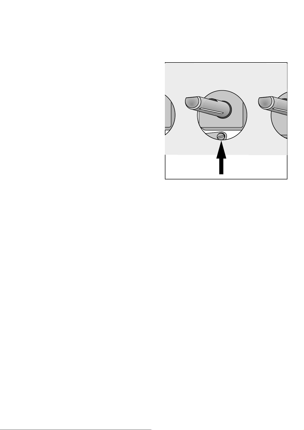
Re-ignite the burner and set to MIN.
F
Remove the control knob, insert a thin
bladed screwdriver down the hole in the
front panel and turn the adjustment screw
until the flame is steady and does not
extinguish, when the knob is turned from
MIN to MAX. Repeat this procedure for all
burners.
Technical Maintenance
Check at regular intervals the condition and
serviceability of the gas connection hose and pressure
regulator, if any is fitted; in case of malfunction, do
not repair but replace the whole faulty part.
To ensure a smooth and safe operation, it is necessary
to periodically grease the gas taps.
14
Page 2
Electrical connections
Any electrical work required to install this
appliance should be carried out by a
qualified electrician or competent person,
in accordance with the current regulations.
THIS APPLIANCE MUST BE
EARTHED.
The manufacturer declines any liability
should these safety measures not be
observed.
This appliance is designed to be connected
to a 230 V 50Hz AC electrical supply.
Before the appliance is connected:
1) check that the main fuse and the domestic installation
can support the load (see the rating label);
2) check that the power supply is properly earthed in
compliance with the current rules;
3) check the socket or the double pole switch used for
the electrical connection can be easily reached with
the appliance built in the forniture unit. Before
switching on, make sure the electricity supply
voltage is the same as that indicated on the appliance
rating plate. The rating plate is located on the bottom
of the hob. A copy is attached on the back cover of
this book.
The appliance is supplied with a 3 core flexible
supply cord incorporating a plug. Connect the plug to
an adequate socket.
Permanent Connection
In the case of a permanent connection, it is necessary
that you install a double pole switch between the
appliance and the electricity supply (mains), with a
minimum gap of 3 mm. between the switch contacts
and of a type suitable for the required load in
compliance with the current electric regulations.
The switch must not break the yellow and green earth
cable at any point.
Ensure that the hob supply cord does not
come into contact with surfaces with
temperatures higher than 50 deg. C.
13
Page 3
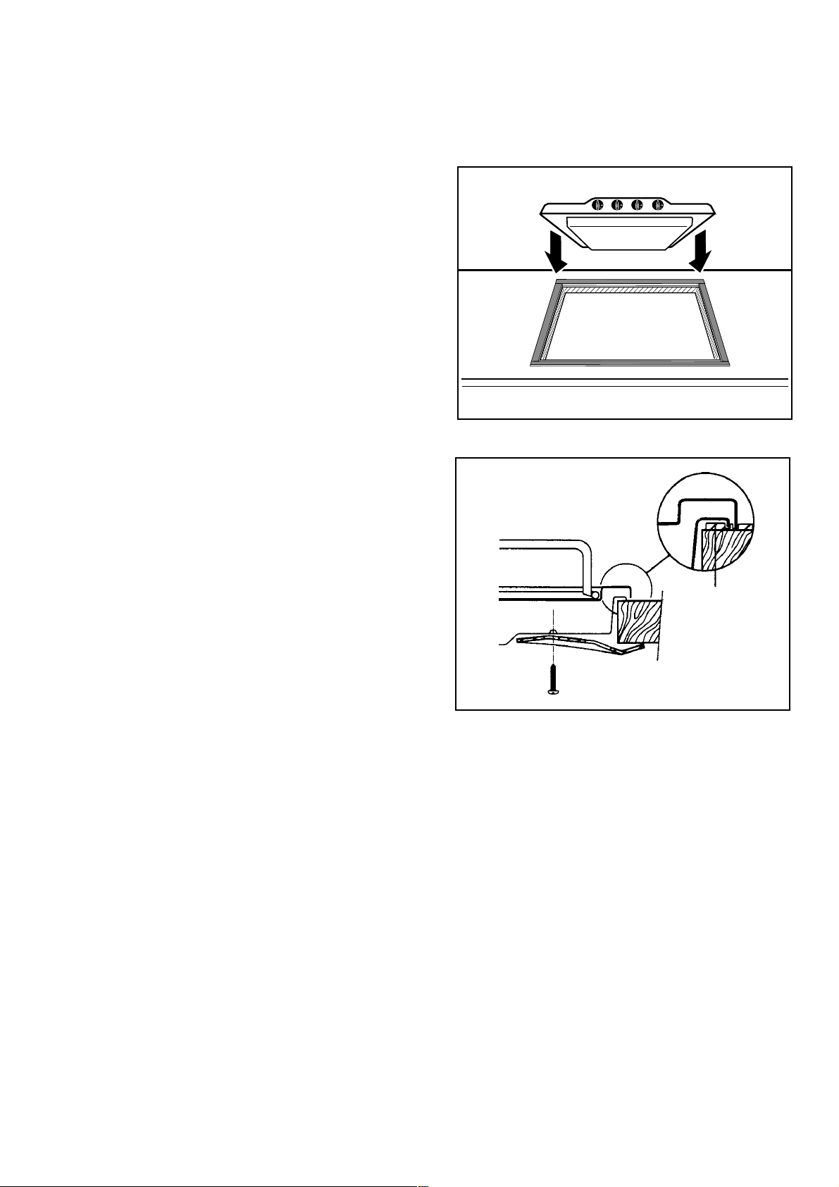
Fitting the hob to the worktop
Carry out the building in of the hob as follows:
put the seals supplied with the hob, on the
F
edges of the cut out, as shown in the diagram,
taking care that the seals meet without
overlapping;
place the hob in the cut out, taking care that it
is centred;
fix the hob with the relevant fixing clamps
and screws, as shown in the diagram. When
the screws have been tightened, the excess
seal can be removed.
The edge of the hob forms a double seal which
prevents the ingress of liquids.
FO 2239
FO 0199
Seal
a
12
Page 4
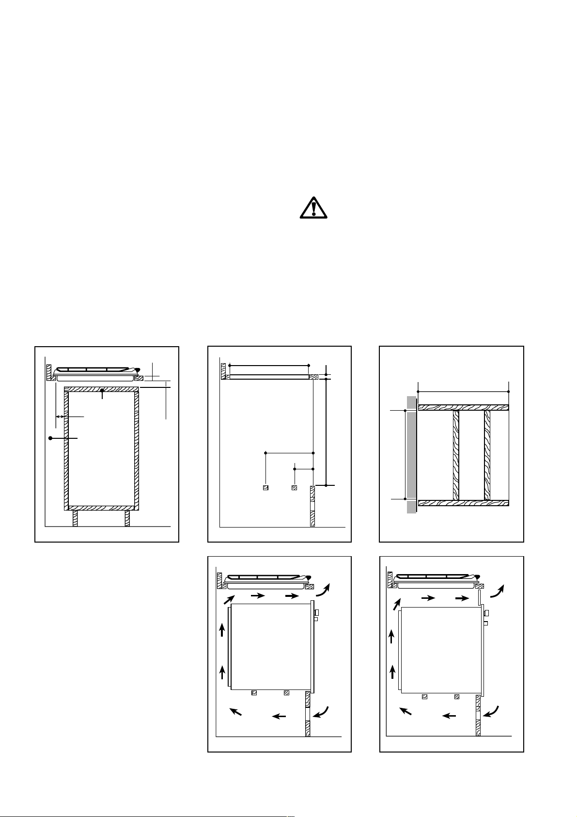
Building In
Building over a cupboard or drawer
If the hob is to be installed above a cupboard or
drawer it will be necessary to fit a heat resistant board
below the base of the hob on the underside of the
work surface.
Building over a kitchen unit with door
Proper arrangements must be taken in designing the
furniture unit, in order to avoid any contact with the
bottom of the hob which can be heated when it is
operated. The recommended solution is shown in
diagram 1.
The panel fitted under the hob ("a") should be easily
removable to allow easy access if technical assistance
is needed. The space behind the kitchen unit ("b") can
be used for connections.
1
30
480
Building over a kitchen unit with oven
If the hob is built into a kitchen unit with an oven
underneath, the recess must have the dimensions
shown in diagrams 2 and 3, and should also incorporate suitable oven crosspiece supports to ensure an
efficient cooling air circulation.
Diagrams 4 and 5 give two building-in examples.
The electric connection of the hob and the
oven should be carried out separately, for
electrical safety reasons to permit easy
extraction of the oven from the front part of
the kitchen unit.
2
30
550 min.
3
a
60
b
FO 2044 FO 2043
20 min
a) Removable panel
b) Room for connections
380
140
591
50 cm
560 min.
FO 0198
4
2
120 cm
5
2
FO 2041
360 cm
2
FO 2042
180 cm
2
11
Page 5

Installation
IMPORTANT
This appliance must be installed by qualified
personnel.
The manufacturer will not accept liability,
should the above instructions or any of the
other safety instructions incorporated in
this book be ignored.
Gas Connection
On the end of the shaft (A) , which includes the GJ 1/
2" threaded elbow, an adjustable joint is fixed so that
the washer (B) is fitted between the components as
shown in the diagram.
A drop of paint at both edges of the "L" joint (C) will
evidence that the good seal of the connection has
been tested in the factory.
Before connecting the gas supply pipe to the joint
(C), the installer will ensure that the paint drop is
unbroken and the "L" connector has not been moved
by the vibrations during handling and transportation.
When the final connection has been made, it is
essential that a thorough leak test is carried out on the
hob and installation.
Ensure that the main connection pipe does not exert
any strain on the hob.
Cut Out Size
The dimensions of the cut-out are given in the
diagram.
FO 1010
A) End of shaft with nut
B) Washer
C) Adjustable joint
Rectangular cut-out size for hob
55 min.
480
10
560
Dimensions are given in mm.
FO 2038
150 min
Page 6

Instructions for the Installer
Engineer technical data
OVERALL DIMENSIONS
Width: 580 mm.
Depth: 510 mm.
Height: 84 mm.
Weight: 11 Kg.
CUT OUT DIMENSIONS
Width: 560 mm.
Depth: 480 mm.
Thickness: 30 mm.
Burner Nominal Power
kW kCal/h Nozzle g/h mbar (*)
Supply Connections
Gas:
RC 1/2 inch (1/2 inch male) Rear right hand corner
Electric:
230 V 50Hz supply, 3 core flexible cable with non
rewireable plug.
Appliance Gas supply: LPG 30 mbar
Appliance Class: 3
Appliance category: I 3
LPG (Butane "A")
Diameter Feeding
Tap. By-Pass Pressure
Auxiliary (dia. 42 mm.) 0,95 814 50 75 28
Semi-rapid (dia. 57 mm.) 1,60 1368 65 126 35 30
Powered Rapid (dia. 90 mm.) 2,9 2475 85 228 45
(*) 1 mbar = 10 mm. water coloumn.
9
Page 7

Something Not Working?
If the appliance is not working correctly, please carry out the following checks before contacting your local
Service Centre.
SYMPTOM
n There is no spark when lighting the gas
n The gas ring burns unevenly
If after all these checks, your appliance still does not
operate correctly, contact your local Service Centre.
SOLUTION
u Check that the unit is plugged in and the electrical
supply is switched on.
u Check the mains fuse has not blown.
u Check the burner cap and crown have been
replaced correctly, e.g. after cleaning.
u Check the main jet is not blocked and the burner
crown is clear of food particles.
u Check the burner cap and crown have been
replaced correctly, e.g. after cleaning.
8
Page 8

Maintenance and Cleaning
Before any maintenance or cleaning can be
carried out, you must DISCONNECT the
hob from the electricity supply.
The hob is best cleaned whilst it is still warm, as
spillage can be removed more easily than if it is left
to cool.
The Hob Top
Regularly wipe over the hob top using a soft cloth
well wrung out in warm water to which a little
washing up liquid has been added. Avoid the use of
the following:
- household detergent and bleaches;
- impregnated pads unsuitable for non-stick saucepans;
- steel wool pads;
- bath/sink stain removers.
Should the hob top become heavily soiled, it is
recommended that a cleaning product such as Hob
Brite or Bar Keepers Friend is used.
Pan Supports
To keep the pan supports in the correct position, they
are hooked into hinges at the back of the hob.
The pan supports can be lifted for easier cleaning, as
shown in fig. 1.
To remove the pan supports completely, proceed as
shown in fig. 2.
The pan supports are dishwasher proof. If washing
them by hand, take care when drying them as the
enamelling process occasionally leaves rough edges.
If necessay, remove stubborn stains using a paste
cleaner.
FO 2237
Fig. 1
The Burners
The burner caps and crowns can be removed for
cleaning.
Wash the burners taps and crowns using hot soapy
water, and remove marks with a mild paste cleaner. A
well moistened soap impregnated steel wool pad can
be used with caution, if the marks are particularly
difficult to remove.
After cleaning, be sure to wipe dry with a soft cloth.
FO 2032
Fig. 2
7
Page 9

Operation
This hob is provided with a safety device,
i
which will stop the gas flow if the flame
accidentally goes off during cooking.
To light a burner, turn the relevant control knob
anticlockwise to maximum position and push it down
to ignite. Keep the control knob pressed down for
about 5 seconds, to allow the safety device to be
switched off. Then adjust the flame as required.
If the burner does not ignite, turn the control knob to
zero, and try again.
When switching on the mains, after
i
installation or a power cut, it is quite normal
for the spark generator to be activated
automatically.
To ensure maximum burner efficiency, you should
only use pots and pans with a flat bottom fitting the
size of the burner used (see table).
Burner minimum maximum
diameter diameter
Large (rapid) 180 mm. 260 mm.
Medium (semi-rapid) 120 mm. 220 mm.
Small (Auxiliary) 80 mm. 160 mm.
If you use a saucepan which is smaller than
the recommended size, the flame will spread
beyond the bottom of the vessel, causing the
handle to overheat.
As soon as a liquid starts boiling, turn down
i
the flame so that it will barely keep the
liquid simmering.
Take care when frying food in hot oil or fat,
as the overheated splashes could easily
ignite.
If the control knobs become difficult to turn,
please contact your local Service Centre.
6
Page 10

Description of the Hob
32
1
5
6
7
8
1. Hob Top
2. Auxiliary Burner
3. Semi-rapid Burners
4. Powered Rapid Burner
5. Control knob for front left burner (auxiliary)
6. Control knob for back left burner (semi-rapid)
7. Control knob for back right burner (semi-rapid)
8. Control knob for front right burner (powered rapid)
3
4
INSTALLATION
Any gas installation must be carried out by
qualified personnel, and in accordance with
existing rules and regulations.
The relevant instructions are to be found in the
second section of this manual.
Please, ensure that, once the appliance is
installed, it is easily accessible for the
engineer in the event of a breakdown.
WHEN THE HOB IS FIRST INSTALLED
Once the hob has been installed, it is
important to remove any protective
materials, which were put on in the factory.
5
Page 11

Contents
For the User
Description
of the Hob Page 5
Operation Page 6
Maintenance
and Cleaning Page 7
Something
Not Working Page 8
For the Installer
Technical Data Page 9
Installation Page 1 0
Gas Connection Page 1 0
Building In Page 1 1
Fitting the Hob
to the Worktop Page 12
Electrical Connection Page 1 3
Commissioning Page 1 4
Technical Maintenance Page 1 4
Guide to Use the instructions
The following symbols will be found in the text to
guide you throughout the Instructions:
Safety Instructions
F
4
Step by step instructions for an
operation
Hints and Tips
i
Page 12

Important Safety Information
Installation
You MUST read these warnings carefully before installing or using the
appliance.
l This appliance must be installed by qualified
personnel, according to the manufacturers
instructions and to the rules in force.
l Remove all packaging before using the appliance.
l Ensure that the gas and electrical supply complies
with the type stated on the rating plate, located near
the gas supply pipe.
l Do not attempt to modify the appliance in any way.
Child Safety
l This appliance is designed to be operated by adults.
Do not allow children to play near or with the
appliance.
l The appliance gets hot when it is in use. Children
should be kept away until it has cooled.
l Children can also injure themselves by pulling pans
or pots off the hob.
l When using other electrical appliances, ensure the
cable does not come into contact with the hot
surfaces of the cooking appliance.
l Unstable or misshapen pans should not be used on
the hob as unstable pans can cause an accident by
tipping or spillage.
l Never leave the hob unattended when cooking with
oil and fats.
l Never use plastic or aluminium foil dishes on the
hob.
l Perishable food, plastic items and areosols may be
affected by heat and should not be stored above or
below the hob unit.
Service
l This appliance should only be repaired or serviced
by an authorised Service Engineer and only genuine approved spare parts should be used.
During Use
l This appliance is intended for domestic cooking only.
It is not designed for commercial or industrial
purposes.
l When in use a gas cooking appliance will produce
heat and moisture in the room in which it has been
installed. Ensure there is a continuous air supply,
keeping air vents in good condition or installing a
cooker hood with a venting hose.
l When using the hob for a long period time, the
ventilation should be improved, by opening a
window or increasing the extractor speed.
l Do not use this appliance if it is in contact with water.
Do not operate the appliance with wet hands.
l Ensure the control knobs are in the OFF position
when not in use.
Environmental Information
l After installation, please dispose of the packaging
with due regard to safety and the environment.
l When disposing of an old appliance, make it
unusable, by cutting off the cable.
Keep this instruction book for future
reference and ensure it is passed on
to any new owner.
3
Page 13

GAS HOB
MODELS
PW 64
PN 64
PX 64
PTDF 64
INSTRUCTION BOOKLET
2
 Loading...