

Page 1
Models PL30WC51EC
PL36WC51EC
PL42WC51EC
ENGLISH.....................................2
FRANÇAIS................................10
Page 2
READ AND SAVE THESE INSTRUCTIONS
!
INTENDED FOR DOMESTIC COOKING ONLY
!
WARNING
TO REDUCE THE RISK OF FIRE, ELECTRIC SHOCK, OR INJURY TO PERSONS, OBSERVE THE FOLLOWING:
1. Use this unit only in the manner intended by the manufacturer. If you have questions, contact the manufacturer at the address or
telephone number listed in the warranty.
2. Before servicing or cleaning unit, switch power off at service panel and lock service panel to prevent power from being switched on
accidentally. When the service disconnecting means cannot be locked, securely fasten a prominent warning device, such as a tag,
to the service panel.
3. Installation work and electrical wiring must be done by a qualified person(s) in accordance with all applicable codes and standards,
including fire-rated construction codes and standards.
4. Sufficient air is needed for proper combustion and exhausting of gases through the flue (chimney) of fuel burning equipment to prevent
backdrafting. Follow the heating equipment manufacturer’s guidelines and safety standards such as those published by the National
Fire Protection Association (NFPA), and the American Society for Heating, Refrigeration and Air Conditioning Engineers (ASHRAE),
and the local code authorities.
5. When cutting or drilling into wall or ceiling, do not damage electrical wiring and other hidden utilities.
6. Ducted fans must always be vented to the outdoors.
7. Do not use this unit with any separate solid-state speed control device.
8. To reduce the risk of fire, use only metal ductwork.
9. This unit must be grounded.
TO REDUCE THE RISK OF A RANGE TOP GREASE FIRE:
A. Never leave surface units unattended at high settings. Boilovers cause smoking and greasy spillovers that may ignite. Heat oils
slowly on low or medium settings.
B. Always turn hood ON when cooking at high heat or when flambeing food (i.e. Crepes Suzette, Cherries Jubilee, Peppercorn Beef
Flambe’).
C. Clean ventilating fans frequently. Grease should not be allowed to accumulate on fan or filter.
D. Use proper pan size. Always use cookware appropriate for the size of the surface element.
WARNING
TO REDUCE THE RISK OF INJURY TO PERSONS IN THE EVENT OF A RANGE TOP GREASE FIRE, OBSERVE THE FOLLOWING:*
1. SMOTHER FLAMES with a close-fitting lid, cookie sheet, or metal tray, then turn off the burner. BE CAREFUL TO PREVENT BURNS.
If the flames do not go out immediately, EVACUATE AND CALL THE FIRE DEPARTMENT.
2. NEVER PICK UP A FLAMING PAN - You may be burned.
3. DO NOT USE WATER, including wet dishcloths or towels - violent steam explosion will result.
4. Use an extinguisher ONLY if:
A. You know you have a Class ABC extinguisher and you already know how to operate it.
B. The fire is small and contained in the area where it started.
C. The fire department is being called.
D. You can fight the fire with your back to an exit.
* Based on “Kitchen Fire Safety Tips” published by NFPA.
!
CAUTION
1. To reduce risk of fire and to properly exhaust air, be sure to duct air outside. Do not vent exhaust air into spaces within walls or
ceilings or into attics, crawl spaces, or garages.
2. Take care when using cleaning agents or detergents.
3. Avoid using food products that produce flames under the Range Hood.
4. For general ventilating use only. Do not use to exhaust hazardous or explosive materials and vapors.
5. To avoid motor bearing damage and noisy and/or unbalanced impellers, keep drywall spray, construction dust, etc. off power unit.
6. Your hood motor has a thermal overload which will automatically shut off the motor if it becomes overheated. The motor will restart
when it cools down. If the motor continues to shut off and restart, have the hood serviced.
7. For best capture of cooking impurities, the bottom of the hood should be a minimum of 24" and a maximum of 30" above the cooking
surface. See “Install Mounting Bracket” section for mounting restrictions.
8. Two installers are recommended because of the large size and weight of this hood.
9. Please read specification label on product for further information and requirements.
- 2 -
Page 3
OPERATION
Controls
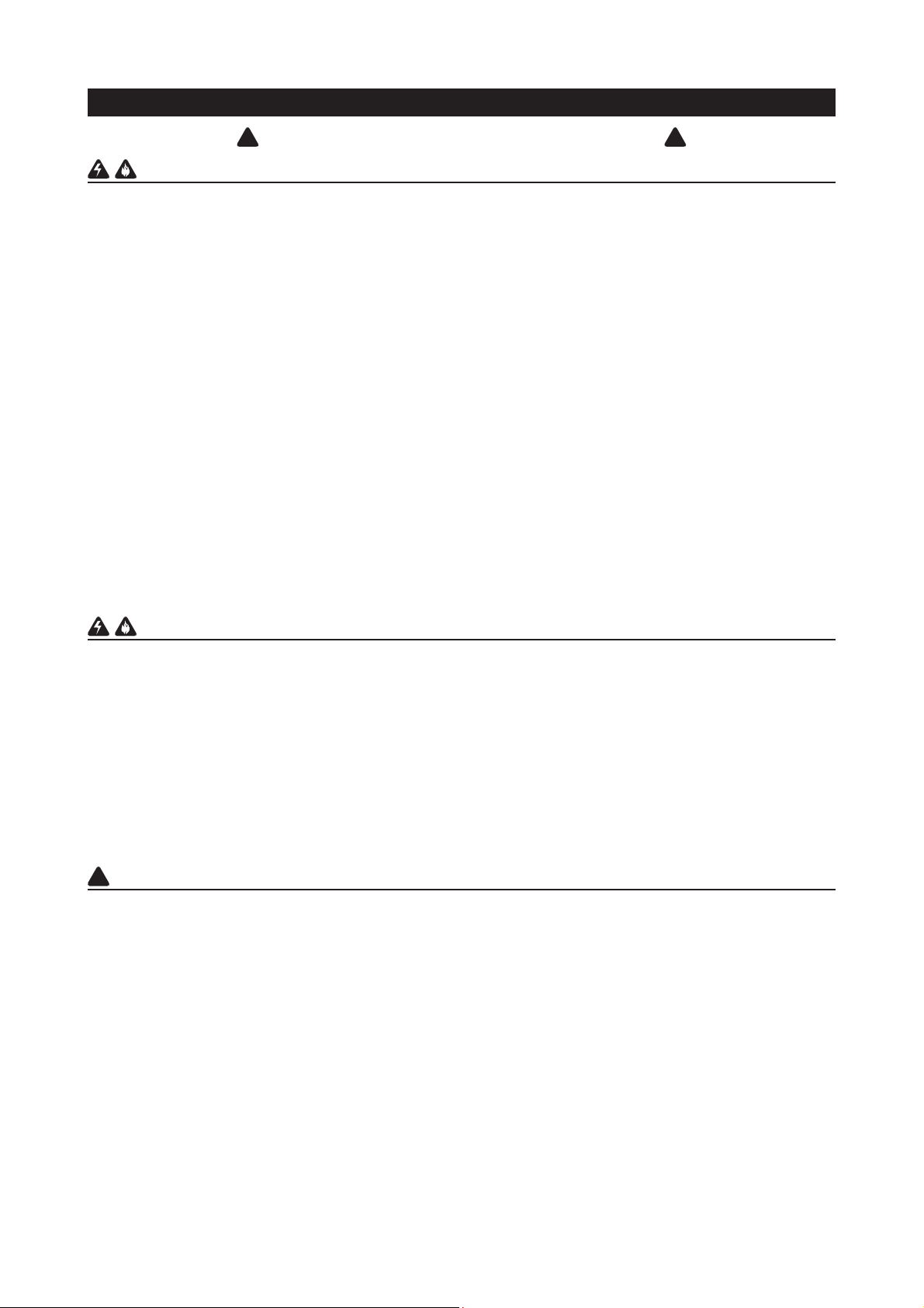
The hood is operated using the (4) push-buttons located at eye-level, on the front
edge of the hood.
The light switch turns the halogen lamps on and off.
The blower on-low / off switch turns the blower on to its lowest running speed. The
blower must be turned on using this switch. Turn the blower off by pressing this
switch a second time.
The blower medium speed switch changes the blower speed to medium. This
switch works only if the blower is already running at low or high speed.
The blower high speed switch changes the blower speed to high. This switch works
only if the blower is already running at low or medium speed.
The pilot lamp lights up whenever the blower is on.
HALOGEN BULBS
This range hood requires two halogen bulbs (Type GU10, MR16 shielded, 120V,
50W).
ALWAYS SWITCH OFF THE ELECTRICITY SUPPLY BEFORE CARRYING OUT
ANY OPERATIONS ON THE APPLIANCE.
1. Loosen the ring nut by turning it counterclockwise.
2. Loosen the bulb by turning it counterclockwise; pull the bulb downwards to
remove. CAUTION: BULB MAY BE HOT!
3. Replace with Type GU10, MR16 shielded, 120V, 50W halogen bulb.
LIGHT
SWITCH
BLOWER
ON-LOW /
OFF
SWITCH
BLOWER
MEDIUM
SPEED
BLOWER
HIGH
SPEED
BULB
PILOT
LAMP
FIG. 1
RING NUT
FIG. 2
MAINTENANCE
Proper maintenance of the Range Hood will assure proper performance of the unit.
Grease Filters
The grease filters should be cleaned frequently. Use a warm detergent solution. Grease filters are dishwasher safe.
See “INSTALL FILTERS” section for removal and installation instructions.
Non-Ducted Recirculation Filters
The non-ducted recirculation filters should be changed every 6 months.
See “INSTALL FILTERS” section for removal and installation instructions.
Hood Cleaning
Stainless steel is one of the easiest materials to keep clean. Occasional care will help preserve its fine appearance.
Cleaning tips:
● Hot water with soap or detergent is all that is usually needed.
● Follow all cleaning by rinsing with clear water. Wipe dry with a clean, soft cloth to avoid water marks.
● For discolorations or deposits that persist, use a non-scratching household cleanser or stainless steel polishing
powder with a little water and a soft cloth.
● For stubborn cases, use a plastic scouring pad or soft bristle brush together with cleanser and water. Rub lightly in
direction of polishing lines or "grain" of the stainless finish. Avoid using too much pressure which may mar the surface.
● DO NOT allow deposits to remain for long periods of time.
● DO NOT use ordinary steel wool or steel brushes. Small bits of steel may adhere to the surface causing rust.
● DO NOT allow salt solutions, disinfectants, bleaches, or cleaning compounds to remain in contact with stainless steel
for extended periods. Many of these compounds contain chemicals which may be harmful. Rinse with water after
exposure and wipe dry with a clean cloth.
Painted surfaces should be cleaned with warm water and mild detergent only.
- 3 -
Page 4
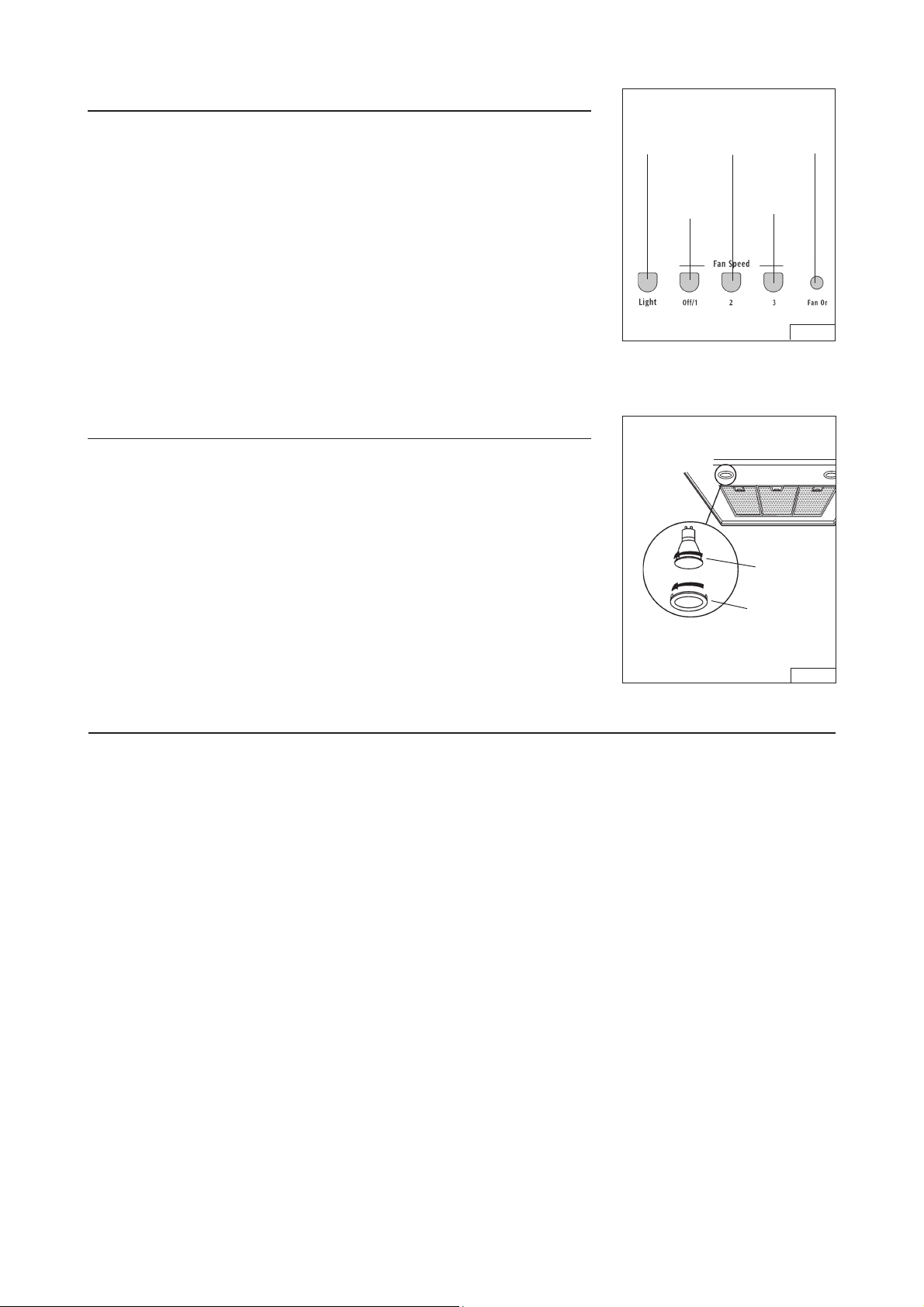
PREPARE THE HOOD
Unpack hood and check contents.
You should receive:
1 - Hood
1 - Decorative Flue Assembly
1 - Parts Bag containing:
1 - Mounting Bracket
1 - Discharge Collar
1 - Flue Mounting Bracket
8 - Mounting Screws (4,8 x 38mm Pan Head)
4 - Mounting Screws (3,9 x 9,5mm Pan Head)
2 - Mounting Screws (3.9 x 6mm Flat Head)
8 - Drywall Anchors
1 - Installation Instructions
2 MOUNTING BRACKET
SCREWS
(3.9 x 6mm Flat Head)
MOUNTING
BRACKET
DISCHARGE
COLLAR
4 MOUNTING
SCREWS (3.9 x
9.5mm Pan Head)
DECORATIVE
FLUE
FLUE MOUNTING
BRACKET
8 MOUNTING SCREWS
(4.8 x 38mm Pan Head)
8 DRYWALL
ANCHORS
FIG. 3
- 4 -
Page 5
INSTALL THE DUCTWORK
(DUCTED HOODS ONLY)
!
CAUTION: To reduce the risk of fire, use only metal ductwork.
1. Decide where the ductwork will run between the hood and the outside.
ROOF CAP
6”
ROUND DUCT
2. A straight, short duct run will allow the hood to perform most efficiently.
3. Long duct runs, elbows, and transitions will reduce the performance of the
hood. Use as few of them as possible. Larger ducting may be required for best
performance with longer duct runs.
4. Install a roof or wall cap. Connect round metal ductwork to cap and work back
towards hood location. Use duct tape to seal the joints between ductwork sections.
INSTALL ELECTRICAL
(DUCTED AND NON-DUCTED HOODS)
WARNING: Electrical wiring must be done by a qualified person(s) in accor-
dance with all applicable codes and standards. This range hood must be
properly grounded. Turn off electrical power at service entrance before wiring.
1. Plan where the hood will be located above the cook top. Refer to the “INSTALL
MOUNTING BRACKET” section for hood mounting height options.
2. Install a standard 2” x 4” wall outlet box and 3-blade 125 volt, 15 Amp grounded
receptacle.
3. Mount the 18” to 22” below the bottom of the hood.
4. Locate the receptacle within the boundary shown and off center of the ductwork
(to allow for power cord plug and flue clearance).
DECORATIVE
FLUE
HOOD
24” TO 30” ABOVE
COOKING SURFACE (see
“INSTALL MOUNTING
BRACKETS” section for
mounting restrictions
6-1/2”
3-1/4”
WALL
CAP
ROUND
ELBOW
6”
ADAPTER
FIG. 4
18” to 22”
INSTALL MOUNTING BRACKET
(DUCTED AND NON-DUCTED HOODS)
1. Construct wood wall framing that is
Make sure:
a) the framing is centered over installation location.
b) the height of the framing will allow the mounting bracket to be secured to
the framing within the dimensions shown.
2.
After wall surface is finished, secure mounting bracket to framing using dimensions shown.
CEILING HEIGHT
8-FOOT
9-FOOT
10- FOOT (see note b)
37-7/8” 38-7/8” 39-7/8”
HOOD DISTANCE ABOVE 36” HIGH COOK TOP (see note a)
24” 25” 26” 27” 28” 29”
MOUNTING BRACKET LOCATION ABOVE 36” HIGH COOK TOP
Note a - Minimum hood distance above cook top must not be less than 24”.
A maximum 30” above cook top is highly recommended for best capture of cooking
impurities.
Distances over 30” are at the installers discretion; and if ceiling height and flue length
permit.
Note b - a 10-foot high celing requires use of an optional flue extension, available
from your local dealer.
flush with interior surface of wall studs.
30”
41-7/8” 42-7/8”
39-7/8” 40-7/8” 41-7/8” 42-7/8”
43-7/8”
43-7/8”
- 5 -
FRAMING BEHIND WOOD CROSS
SUPPORT
DRYWALL
WOOD
CROSS
SUPPORT
FIG. 5
FIG. 6
Page 6
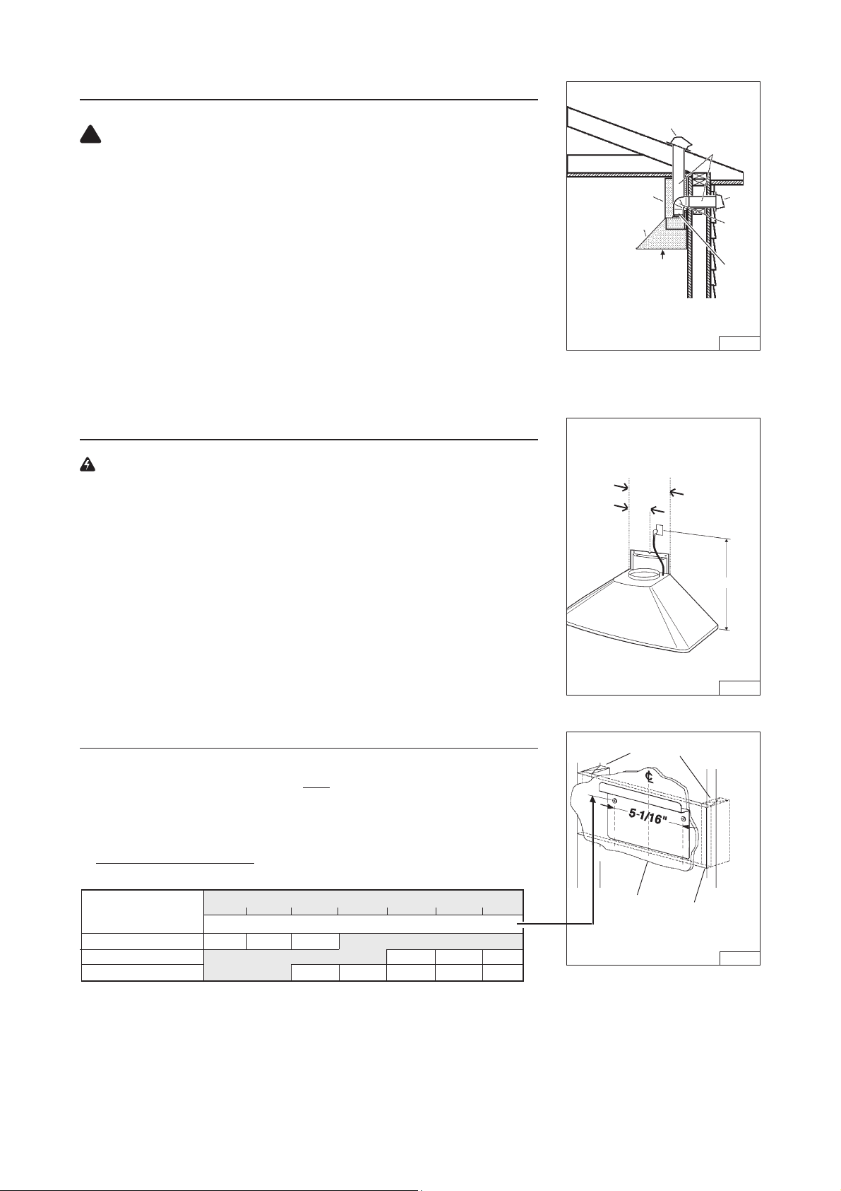
INSTALL FLUE MOUNTING BRACKET
(DUCTED AND NON-DUCTED HOODS)
1. Assemble the flue mounting bracket, adjusting outside width as shown. See Figure 7.
2. Carefully center the mounting bracket directly over the range hood location.
3. Secure the bracket assembly to the ceiling using (2) 4.8x38mm mounting screws and drywall anchors (Fig. 8). Make sure
the bracket is pushed into the corner, tight against the wall and centered over the hood.
FLUE MOUNTING BRACKET
DRYWALL ANCHORS
3.9 x 6 mm
FLAT HEAD
BRACKET SCREWS
7-3/4”
(196.8 mm)
FIG. 7
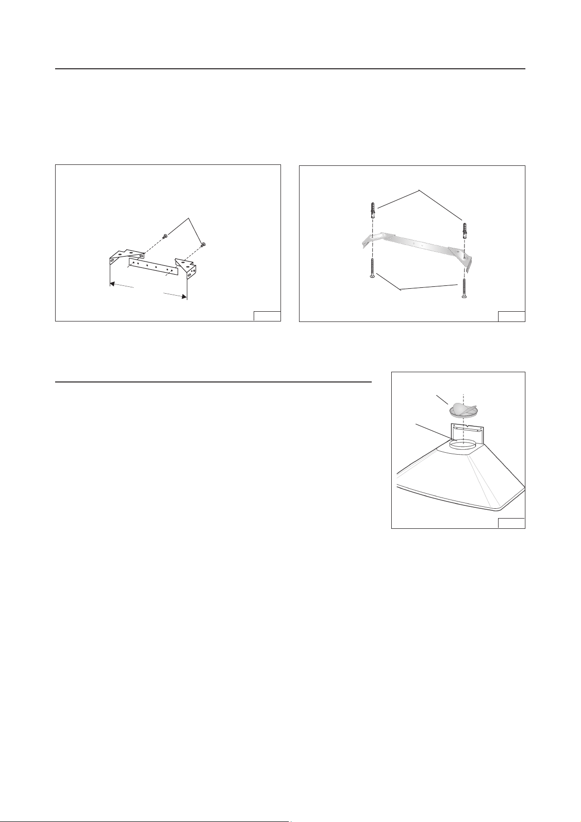
PREPARE THE HOOD
Note: On stainless steel hoods, carefully remove the plastic protective film
from all exterior surfaces of the hood and decorative flues, prior to final
installation.
(DUCTED HOODS ONLY)
Install the discharge collar into the duct connector of the range hood. Fig. 9.
4.8x38mm
MOUNTING SCREWS
DISCHARGE
COLLAR
DUCT
CONNECTOR
FIG. 8
FIG. 9
- 6 -
Page 7

PREPARE THE HOOD
(NON - DUCTED HOODS ONLY)
Note: The following materials must be purchased separately for non-ducted recirculation installations.
• Non - Ducted Recirculation Kit, Model DFKTWC51EC.
• 5” diameter metal duct.
1. Discard discharge collar and damper supplied with the hood. Install the 5” to 6” adapter supplied with the Non-Ducted
Recirculation Kit. Fig. 10.
2. Secure the plenum to the flue mounting bracket with (2) 3.9x6mm flat head screws (the screws are supplied with the
Non-Ducted Recirculation Kit “DFKTWC51EC”). Fig. 11.
5”-6”
ADAPTER
3.9x6mm
FLAT HEAD
SCREWS
PLENUM
FIG.10
FLUE MOUNTING
BRACKET
FIG.11
INSTALL THE HOOD
(DUCTED AND NON-DUCTED HOODS)
Note: at least two people will be required to mount the hood.
1. Raise the hood into its mounting position.
2. Align the rectangular opening on the back of the hood with the wall-mounting bracket. Gently lower the hood until it
securely engages the bracket. Fig. 12.
3. Level the hood with 2 mounting screws (3.9x9.5mm) and secure with (4) mounting screws. Use drywall anchors provided
if wall studs or framing are not available. Fig. 12.
4. On ducted hoods, attach 6” round metal duct between the hood’s blower collar and duct that leads to the outside location.
5. On non-ducted hoods, attach 5” round metal expandable duct between the 5”-6” adapter on the hood and the connector
on the plenum.
6. Tape all duct joints to make them secure and air tight.
7. Plug the power cord into the electric wall receptacle. Tuck excess cord behind the flue.
MOUNTING SCREWS
(3.9x9.5mm)
MOUNTING SCREWS
(4.8x38mm)
MOUNTING SCREWS
(4.8x38mm)
- 7 -
WALL FRAMING
MOUNTING
BRACKET
RECTANGULAR
CUTOUT
FIG.12
Page 8

INSTALL THE HOOD, cont’d
8. Carefully place the decorative flue on the hood. Fig. 13.
- On ducted installation in rooms with 8-foot ceilings, the air vents are concealed. Install the flue with the air vents
down.
- On non-ducted installations in rooms with 8-foot ceilings, the air vents are exposed. Install the flue with the air vents
up.
- On ducted and non-ducted installations in rooms with 9-foot ceilings, the vents are exposed. Install the flue with air
vents up.
ROOMS WITH 10-FOOT CEILINGS
(DUCTED HOODS ONLY)
Rooms with 10-foot ceilings require flue extension model FXWC51EC available from your local dealer.
9. Discard the upper flue supplied with the product. Replace it with the flue extension.
10. Raise the upper flue until its holes align with holes in the flue mounting bracket (located on ceiling). Fig. 14.
12. Secure the flue with (2) 3.9x9.5mm mounting screws. Fig. 14.
LOWER
FLUE
INSTALL FILTERS
UPPER FLUE
VENTS EXPOSED
UPPER
FLUE
LOWER
FLUE
UPPER FLUE
VENTS
CONCEALED
FIG. 13
3.9x9.5mm
MOUNTING SCREWS
FIG.14
(DUCTED AND NON-DUCTED HOODS)
1. To remove the GREASE filter, push in on the metal latch tab and tilt filter
downward to remove.
2. To install the GREASE filter, align rear filter tabs with slots in the hood. Depress
the metal latch tab, push filter into position and release. Make sure filter is
securely engaged after installation.
NOTE: Prior to use, remove protective film from the filter frame.
(NON-DUCTED HOODS ONLY)
1. To remove the NON-DUCTED RECIRCULATION filters, rotate them.
2. To install the NON-DUCTED RECIRCULATION filters, position the filter over
the blower; rotate to lock filters in place (Fig. 16).
3. Install GREASE filters after Non-ducted Recirculation filters are installed.
- 8 -
GREASE FILTERS
FIG.15
NON-DUCTED
RECIRCULATION
FILTERS
FIG.16
Page 9

Major Appliance Warranty Information
Your appliance is covered by a one year limited warranty. For one year from your original date of
purchase, Electrolux will pay all costs for repairing or replacing any parts of this appliance that prove to
be defective in materials or workmanship when such appliance is installed, used and maintained in
accordance with the provided instructions.
Exclusions This warranty does not cover the following:
1. Products with original serial numbers that have been removed, altered or cannot be readily
determined.
2. Product that has been transferred from its original owner to another party or removed outside the USA
or Canada.
3. Rust on the interior or exterior of the unit.
4. Products purchased "as-is" are not covered by this warranty.
5. Food loss due to any refrigerator or freezer failures.
6. Products used in a commercial setting.
7. Service calls which do not involve malfunction or defects in materials or workmanship, or for
appliances not in ordinary household use or used other than in accordance with the provided
instructions.
8. Service calls to correct the installation of your appliance or to instruct you how to use your appliance.
9. Expenses for making the appliance accessible for servicing, such as removal of trim, cupboards,
shelves, etc.,which are not a part of the appliance when it is shipped from the factory.
10. Service calls to repair or replace appliance light bulbs, air filters, water filters, other consumables, or
knobs, handles, or other cosmetic parts.
11. Surcharges including, but not limited to, any after hour, weekend, or holiday service calls, tolls, ferry
trip charges, or mileage expense for service calls to remote areas, including the state of Alaska.
12. Damages to the finish of appliance or home incurred during installation, including but not limited to
floors, cabinets, walls, etc.
13. Damages caused by: services performed by unauthorized service companies; use of parts other than
genuine Electrolux parts or parts obtained from persons other than authorized service companies; or
external causes such as abuse, misuse, inadequate power supply, accidents, fires, or acts of God.
DISCLAIMER OF IMPLIED WARRANTIES; LIMITATION OF REMEDIES
CUSTOMER’S SOLE AND EXCLUSIVE REMEDY UNDER THIS LIMITED WARRANTY SHALL BE
PRODUCT REPAIR OR REPLACEMENT AS PROVIDED HEREIN. CLAIMS BASED ON IMPLIED
WARRANTIES, INCLUDING WARRANTIES OF MERCHANTABILITY OR FITNESS FOR A PARTICULAR
PURPOSE, ARE LIMITED TO ONE YEAR OR THE SHORTEST PERIOD ALLOWED BY LAW, BUT NOT
LESS THAN ONE YEAR. ELECTROLUX SHALL NOT BE LIABLE FOR CONSEQUENTIAL OR
INCIDENTAL DAMAGES SUCH AS PROPERTY DAMAGE AND INCIDENTAL EXPENSES RESULTING
FROM ANY BREACH OF THIS WRITTEN LIMITED WARRANTY OR ANY IMPLIED WARRANTY. SOME
STATES AND PROVINCES DO NOT ALLOW THE EXCLUSION OR LIMITATION OF INCIDENTAL OR
CONSEQUENTIAL DAMAGES, OR LIMITATIONS ON THE DURATION OF IMPLIED WARRANTIES, SO
THESE LIMITATIONS OR EXCLUSIONS MAY NOT APPLY TO YOU. THIS WRITTEN WARRANTY GIVES
YOU SPECIFIC LEGAL RIGHTS. YOU MAY ALSO HAVE OTHER RIGHTS THAT VARY FROM STATE TO
STATE.
If You Need
Service
This warranty only applies in the USA and Canada. In the USA, your appliance is warranted by Electrolux Major Appliances
North America, a division of Electrolux Home Products, Inc. In Canada, your appliance is warranted by Electrolux Canada
Corp. Electrolux authorizes no person to change or add to any obligations under this warranty. Obligations for service and
parts under this warranty must be performed by Electrolux or an authorized service company. Product features or
specifications as described or illustrated are subject to change without notice.
USA
1.800.944.9044
Electrolux Major Appliances
North America
P.O. Box 212378
Augusta, GA 30907
Keep your receipt, delivery slip, or some other appropriate payment record to establish the warranty period
should service be required. If service is performed, it is in your best interest to obtain and keep all receipts.
Service under this warranty must be obtained by contacting Electrolux at the addresses or phone numbers
below.
Canada
1.800.668.4606
Electrolux Canada Corp.
5855 Terry Fox Way
Mississauga, Ontario, Canada
L5V 3E4
- 9 -
Page 10

LISEZ ET CONSERVEZ CES INSTRUCTIONS
!
SEULEMENT POUR UTILISATION DOMESTIQUE
!
AVERTISSEMENTS
POUR REDUIRE LES RISQUES D’INCENDIE, DE DECHARGES ELECTRIQUES OU DE DOMMAGES AUX PERSONNES,
OBSERVEZ LES INSTRUCTIONS SUIVANTES:
1. N’utilisez cet appareil que comme cela est indiqué par le constructeur. Si vous avez des problèmes, contactez le fabriquant à l’adresse
ou au numéro de téléphone indiqués dans la garantie.
2. Avant de pourvoir à l’entretien ou au nettoyage de votre appareil, éteignez-le au tableau des commandes ou bloquez le tableau des
commandes afin d’éviter de le mettre en marche accidentellement. Si vous ne pouvez pas bloquer le système permettant d’éteindre
votre appareil, appliquez un avertissement extérieur d’une façon sure, comme par exemple un panneau, sur le tableau des commandes.
3. L’assemblage et la connexion électrique doivent être faits par des personnes qualifiées en respectant les normes et règlement s en
vigueur, y compris les normes et règlements concernant les possibilités d’incendie.
4. Il est indispensable qu’il y ait suffisamment d’air pour que la combustion et l’évacuation des gaz à travers le tuyau du brûleur du
combustible ait lieu sans retour de flamme. Suivez les indications données par le fabricant du brûleur ainsi que les normes de sécurité
comme celles qui sont publiées par l’Association Nationale pour la Protection contre les Incendies National Fire Protection Association
(NFPA) et la American Society for Heating, Refrigeration and Air Conditioning Engineers (ASHRAE), et les autorités locales en matière
de normes.
5. Quand vous coupez ou percez des trous dans le mur ou le plafond, n’abîmez pas les fils électriques ou autres.
6. Le ventilateur canalisé doit toujours évacuer l’air vers l’extérieur.
7. N’utilisez pas cet appareil avec un appareil contrôlant la vitesse à état solide.
8. Afin de diminuer tout risque d’incendie n’utilisez que des conduits en métal.
9. Votre appareil doit être relié à la terre.
ATTENTION - POUR REDUIRE LES RISQUES D’INCENDIE DES MATIERES GRASSES QUI SONT EN TRAIN DE CUIRE:
A. Ne laissez jamais ni vos éléments chauffants, ni vos casseroles ou poêles sur le feu sans les contrôler si vous réglez l’apport de
chaleur sur une position élevée. Si vos casseroles ou poêles débordent cela provoque de la vapeur et des éclaboussures de graisse
qui peuvent prendre feu. Chauffez les huiles lentement à feu bas ou moyen.
B. Faites toujours fonctionner votre hotte quand vous cuisez à des températures élevées ou quand vous cuisinez des plats flambés.
(par ex. crêpes Suzette, Cerises “Jubilé”, Steack au poivre flambé).
C. Nettoyez régulièrement les ailes de vos ventilateurs. Ne permettez pas que la graisse s’accumule sur le ventilateur ou sur le filtre.
D. Utilisez des casseroles de taille appropriée. Utilisez toujours des ustensiles de cuisson dont la taille est appropriée à la surface de
votre élément de cuisson.
AVERTISSEMENTS
POUR REDUIRE LES RISQUES DE DOMMAGES AUX PERSONNES AU CAS OÙ VOTRE CUISINIERE PRENDRAIT FEU, OBSERVEZ
LES INSTRUCTIONS SUIVANTES:*
1. ETEINDRE LES FLAMMES à l’aide d’un couvercle le plus hermétique possible, une plaque à gâteaux, ou un plateau en métal, puis
éteindre le brûleur. ATTENTION à NE PAS VOUS BRÛLER. Si les flammes ne s’éteignent pas immédiatement, SORTEZ ET
APPELEZ LES POMPIERS.
2. NE PRENEZ JAMAIS EN MAIN UNE POÊLE OU UNE CASSEROLE QUI A PRIS FEU - Vous pourriez vous brûler.
3. N’UTILISEZ PAS D’EAU, ni torchons ou serviettes mouillés - vous provoqueriez une violente explosion de vapeur.
4. Utilisez un extincteur SEULEMENT si:
A. Vous savez que vous avez un extincteur Classe ABC, et vous en connaissez déjà le mode d’emploi.
B. Ce n’est pas un très gros incendie et qu’il se limite à l’endroi où il a explosé.
C. Vous êtes en train d’avertir les pompiers.
D. Vous avez la possibilité d’essayer d’éteindre l’incendie en ayant le dos tourné vers une issue.
* D’après les “Suggestions concernant la Sécurité contre les incendies des cuisines” publiées par NFPA.
!
ATTENTION
1. Pour réduire tout risque d’incendie et pour évacuer correctement l’air, assurez-vous de prévoir un conduit de ventilation extérieur.
Ne videz pas l’air dans les espaces limités par des murs ou des plafonds, les combles, les passages étroits ou les garages.
2. Faites très attention quand vous utilisez des produits de nettoyage ou des détergents.
3. Évitez d’utiliser des aliments pouvant s’enflammer sous la Range Hood.
4. N’utilisez cet appareil que pour une ventilation générale. Ne l’utilisez pas pour évacuer des matières ou des vapeurs dangereuses
ou qui peuvent exploser.
5. Pour éviter de causer des dommages au moteur et de rendre les rotors bruyants et/ou non équilibrés, évitez que les sprays pour
murs secs, la poussière de construction entrent en contact avec la partie électrique.
6. Le moteur de votre hotte a un thermostat qui éteindra automatiquement le moteur s’il est surchauffé. Le moteur se remettra en
marche lorsqu’il se sera refroidi. Si le moteur continue à s’éteindre et à se remettre en marche, faites vérifier votre hotte.
7. Pour mieux capturer les impuretés de cuisine, le bas de votre hotte devrait être à une distance minimum de 24” et à une distance
maximum de 30” au-dessus du plan de cuisson. Voir la section “ Installation etrier d’assemblage “ pour les restrictions de montage.
8. Vu que cette hotte est grande et lourde, il est recommandé de confier l’installation de cette hotte à deux personnes.
9. Nous vous recommandons de lire l’étiquette indiquant les caractéristiques de votre hotte pour de plus amples informations et
exigences.
- 10 -
Page 11

FONCTIONNEMENT
Commandes
Votre hotte fonctionne grâce à (4) boutons sur lesquels vous devez appuyer et qui
se trouvent à la hauteur de vos yeux, sur le bord antérieur de votre hotte.
Le bouton de la lumière allume et éteint les ampoules halogènes.
Le bouton du ventilateur ON-bas/OFF fait fonctionner le ventilateur à la vitesse la
plus basse. Le ventilateur doit être mis en fonctionnement grâce à ce bouton. Arrêtez
le ventilateur en appuyant une deuxième fois sur ce bouton.
Le bouton du ventilateur vitesse moyenne change la vitesse du ventilateur en
moyenne. Ce bouton ne fonctionne que si le ventilateur fonctionne déjà à une
vitesse basse ou élevée.
Le bouton du ventilateur vitesse élevée change la vitesse du ventilateur en vitesse
élevée. Ce bouton ne fonctionne que si le ventilateur fonctionne déjà à une vitesse
basse ou moyenne.
Le voyant lumineux s’allume quand le ventilateur fonctionne.
AMPOULES HALOGENES
Ce modèle de hotte veut deux ampoules halogènes (Type GU10, MR16 avec
écran, 120V, 50W).
AVANT DE PROCÉDER À QUELCONQUE OPÉRATION, DÉBRANCHEZ
L’APPAREIL.
1. Dévissez la bague dans le sens contraire aux aiguilles d’une montre.
2. Dévissez l’ampoule dans le sens contraire aux aiguilles d’une montre; enlevez
l’ampoule en tirant vers le bas. ATTENTION: L’AMPOULE PEUT ETRE
CHAUDE!
3. Remplacer par une ampoule ayant les mêmes caractéristiques (Type GU10,
MR16 avec écran, 120V, 50W).
BOUTON
LUMIÈRE
VENTILATEUR
VENTILATEUR
BOUTON
ON-bas/OFF
VITESSE
MOYENNE
VENTILATEUR
BAGUE
LUMINEUX
VITESSE
ÉLEVÉE
AMPOULE
VOYANT
FIG. 1
FIG. 2
ENTRETIEN
Un bon entretien de votre hotte garantira une excellente performance.
Filtres à graisse
Les filtres à graisse devront être fréquemment nettoyés. Utilisez une solution à base de détergent tiède. Les filtres à
graisse peuvent aller au lave-vaisselle.
Voir la section “ INSTALLATION DES FILTRES “ pour les instructions d’installation et de retrait.
FILTRES À CHARBON (Configurations non carénées)
Les filtres à charbon devront être changés tous les 6 mois.
Voir la section “ INSTALLATION DES FILTRES “ pour les instructions d’installation et de retrait.
Nettoyage de votre hotte
L’acier inoxydable est une des matières les plus faciles à nettoyer. Un entretien de temps en temps permettra de le
conserver en parfait état. Conseils pour le nettoyage:
● Eau chaude et savon ou détergent est tout ce qui est normalement nécessaire.
● Après chaque nettoyage, rincez bien à l’eau claire. Essuyez avec un chiffon propre et doux afin d’éviter les taches
d’eau.
● Si des décolorations ou des dépôts persistent, utilisez un nettoyant domestique non abrasif ou de la poudre pour
l’acier inoxydable et un peu d’eau et un chiffon doux.
● Dans les cas difficiles, utilisez une éponge en plastique ou une brosse douce avec du nettoyant et de l’eau. Frottez
légèrement en suivant la direction du polissage ou du “grain” de l’acier inoxydable. Evitez de frotter trop fort afin de ne
pas abîmer la surface.
● NE LAISSEZ PAS les taches trop longtemps.
● N’UTILISEZ PAS de laines d’acier ordinaires ou des brosses en acier. Des débris d’acier pourraient adhérer à la
surface et causer de la rouille.
● NE PERMETTEZ PAS que des solutions salées, des désinfectants, des blanchissants ou des produits nettoyants
restent en contact avec l’acier pendant longtemps. Beaucoup de ces produits contiennent des produits chimiques qui
pourraient causer des dommages. Rincez à l’eau immédiatement s’ils entrent en contact et essuyez avec un chiffon
humide.
Les surfaces peintes doivent être nettoyées avec de l’eau tiède additionnée d’un détergent doux seulement.
- 11 -
Page 12

PREPAREZ LA HOTTE
Enlever la hotte dans l’emballage et controller le
contenu.
Vous devez recevoir :
1 - Hotte
1 - Conduit décoratif
1 - Sachet avec:
1 - Support de fixation
1 - Collier d’évacuation
1 - Étrier de support
8 - Vis d’assemblage (4,8 x 38mm Tête ronde)
4 - Vis d’assemblage (3,9 x 9,5mm Tête ronde)
2 – Vis d’assemblage (3,9 x 6 mm Tête plate)
8 - Chevilles
1 - Instructions pour l’installation
2 VIS D’ASSEMBLAGE
(3.9 x 6mm Tête Plate)
SUPPORT
DE FIXATION
COLLIER
D’EVACUATION
4 VIS D’ASSEMBLAGE
(3.9 x 9.5mm Tête
ronde)
CONDUIT
DECORATIF
ETRIER DE SUPPORT
8 VIS D’ASSEMBLAGE
(4.8 x 38mm Tête ronde)
8 CHEVILLES
FIG. 3
- 12 -
Page 13

INSTALLATION DU SYSTEME D’EVACUATION
(UNIQUEMENT POUR LES HOTTES CARÉNÉES)
!
ATTENTION: Pour réduire les risques d’incendie, n’utilisez que des tuyaux
en métal.
1. Décidez où le tuyau rond doit être installé, entre votre hotte et l’extérieur.
2. Un tuyau droit et court permettra à votre hotte de fonctionner d’une façon plus
efficace.
3. Un tuyau long avec des coudes et des transitions réduira le bon fonctionnement
de votre hotte. En utiliser le moins possible. Pour de longues utilisations, il faut
un tuyau d’évacuation d’air ayant un diamètre plus large.
4. Installez un couvercle sur le toit ou au mur. Reliez un tuyau en métal rond au
couvercle et faites-le aller jusqu’à l’emplacement de votre hotte. Rendez les
jonctions du tuyau hermétiques au moyen d’un ruban pour tuyaux.
INSTALLATION ÉLECTRIQUE
(HOTTES CARÉNÉES OU NON CARÉNÉES)
ATTENTION : Les fils électriques doivent être installés par une/des
personne(s) qualifiée(s) conformément à tous les codes et standards
applicables. Cette hotte doit être correctement mise à la terre. Éteignez
l’alimentation électrique à l’entrée du branchement avant la connexion.
1. Bien organiser l’endroit où la hotte sera placée au-dessus du plan de cuisson.
Voir la section “INSTALLATION SUPPORT DE FIXATION” pour les options
relatives à la hauteur de montage de la hotte.
2. Installer une boîte standard de 2" x 4" pour la prise de courant murale et une
prise à la terre à 3 lames, 125 V et 15 Amp.
3. Monter la prise à la terre à 18”-22” de la partie inférieure de la hotte.
4. Placer la boîte dans les limites indiquées et décentrées par rapport au système
de câblage afin de permettre le passage du câble d’alimentation et de
l’évacuation des fumées.
COUVERCLE DU
TOIT
CONDUIT
DÉCORATIF
HOTTE
DE 24”(61cm) À 30” (76cm)
AU-DESSUS DU PLAN DE
CUISSON (voir la section
“SUPPORT DE FIXATION”
pour les instructions
relatives au montage
6-1/2”
3-1/4”
6-1/2” = 165 mm
3-1/4” = 82.5 mm
18” à 22” = 457.2 à 558.8 mm
TUYAU ROND
DE 6” (15cm)
COUVERCLE
DU MUR
COUDE
ROND
6” (15cm)
ADAPTATEUR
FIG. 4
18” à 22”
FIG. 5
INSTALLATION SUPPORT DE FIXATION
(HOTTES CARÉNÉES OU NON CARÉNÉES)
1. Construisez une armature murale en bois affleurée avec une surface intérieure
de poteaux de cloison. Assurez-vous que :
a) l’armature est centrée au- dessus du futur emplacement de la hotte ;
b) la hauteur de l’armature permettra d’y fixer le support de fixation en
respectant les dimensions indiquées.
Après avoir terminé la surface du mur, fixez le support de fixation au cadre en
2.
respectant les dimensions qui sont indiquées.
ESPACEMENT ENTRE LA HOTTE ET LE PLAN DE CUISSON DE 36” DE HAUT
HAUTEUR DU PLAFOND
8-FOOT
9-FOOT
10- FOOT (voir remarque b)
24” 25” 26” 27” 28” 29”
EMPLACEMENT D’ETRIER D’ASSEMBLAGE AU-DESSUS DU PLAN DE
37-7/8” 38-7/8” 39-7/8”
Remarques a - La distance au-dessus du plan de cuisson ne doit pas être inférieure
à 24". Un maximum de 30" est vivement recommandé pour mieux capturer les
impuretés issues de la cuisson.
Les distances supérieures à 30" au-dessus du plan de cuisson sont à la discrétion
des monteurs, à condition que la hauteur de plafond et la longueur des conduites
d’échappement le permettent.
Remarques b - Demande une extension de conduit de l’échappement de 10 pieds
à votre fornisseur.
(VOIR REMARQUE a)
CUISSON DE 36” DE HAUT
41-7/8” 42-7/8”
39-7/8” 40-7/8” 41-7/8” 42-7/8”
- 13 -
30”
43-7/8”
43-7/8”
BÂTI DERRIÈRE L’APPUI
TRANSVERSAL EN BOIS
CLOISON
SÈCHE
APPUI
TRANSVERSAL
EN BOIS
FIG. 6
Page 14

INSTALLATION ETRIER DE SUPPORT
(HOTTES CARÉNÉES OU NON CARÉNÉES)
1. Assemblez l’étrier de support du conduit décoratif en réglant la largeur extérieure comme indiqué. Fig. 7.
2. Centrez soigneusement l’étrier de support directement sur l’emplacement destine à la hotte.
3. Fixez l’etrier de support au plafond au moyen de deux (2) vis de montage de 4,8 x 38 mm et chevilles (Fig. 8). Vérifiez
que le support est enfoncé dans le mur adjacent et qu’il est centré au-dessus de la hotte.
ETRIER DE SUPPORT
CHEVILLES
3,9 x 6 mm VIS
D’ASSEMBLAGE À TÊTE
PLATE
7-3/4”
(196.8 mm)
FIG. 7
PRÉPARATION DE LA HOTTE
Remarque : si la hotte est en acier inoxydable, retirez précautionneusement
le film protecteur des surfaces extérieures et du conduit décoratif avant de
terminer l’installation.
(HOTTES CARÉNÉES)
Installez le collier d’évacuation dans le conduit relié à la hotte (fig. 9).
VIS D’ASSEMBLAGE
4.8x38mm
FIG. 8
COLLIER
D’EVACUATION
CONNECTEUR
DU CONDUIT
FIG. 9
- 14 -
Page 15

PRÉPARATION DE LA HOTTE
(CONFIGURATION NON CARÉNÉE)
Remarque : Le matériel doit être acheté séparément pour des installations non carénées.
• Kit de recirculation non caréné, modèle DFKTWC51EC.
• Conduit en metal de 5" de diamètre.
1. Ne comptez pas le collier d’évacuation ni le clapêt fournis avec la hotte. Installez l’adaptateur de 5" à 6" fourni avec
le kit de recirculation non caréné. (Fig. 10).
2. Fixez le deflecteur à l’etrier de support du conduit decoratif au moyen des (2) vis d’assemblage tête plate 3.9x6mm (les
vis sont fournies avec le Kit de recirculation non caréné “DFKTWC51EC”). Fig. 11.
ADAPTATEUR
DE 5”-6”
FIG.10
VIS
D’ASSEMBLAGE
TÊTE PLATE
3.9x6mm
DEFLECTEUR
ETRIER DE SUPPORT
DU CONDUIT
DECORATIF
FIG.11
INSTALLATION DE LA HOTTE
(HOTTES CARÉNÉES OU NON CARÉNÉES)
Remarque : la hotte doit être installée par au moins deux personnes.
1.Soulevez la hotte et placez-la à l’endroit où elle sera installée.
2.Alignez l’ouverture rectangulaire située à l’arrière de la hotte avec le support de fixation murale. Abaissez lentement
la hotte jusqu’à ce qu’elle s’emboîte avec le support (fig. 12).
3.Mettez la hotte à niveau au moyen des vis d’assemblage (3.9x9.5mm) et fixez-la au moyen de (4) vis de montage. Si
vous ne disposez pas de poteaux de cloison ni d’armature, utilisez les chevilles fournies (fig. 12).
4. Sur les hottes avec tuyau d’évacuation, raccorder un conduit métallique rond de 6" entre le collier de soufflante de
la hotte et le conduit qui mène à l’emplacement extérieur.
5. Sur les hottes recyclant l’air, raccorder un conduit métallique extensible de 5" entre l’adaptateur de 5"-6" sur la
hotte et le connecteur sur le déflecteur.
6. Fixer tous les joints des conduites avec du ruban adhésif pour les rendre plus sûrs et étanches.
7.Branchez le cordon d’alimentation à la prise murale. Faites passer la longueur de cordon qui dépasse derrière le
conduit.
VIS DE
MONTAGE
(3.9x9.5mm)
VIS DE
MONTAGE
(4.8x38mm)
VIS DE
MONTAGE
(4.8x38mm)
PLANCHE DE BOIS POUR L'ADAPTATION
SUPPORT DE
FIXATION
DÉCOUPE
RECTANGULAIRE
FIG.12
- 15 -
Page 16

INSTALLATION DE LA HOTTE, suite
8. Placez précautionneusement le conduit décoratif sur la hotte (Fig. 13).
- Pour les hottes carénées, lorsque le plafond est de 8’, les prises d’air du conduit supérieur sont dissimulées. Installez
le conduit avec les prises d’air vers le bas.
- Pour les hottes non carénées, lorsque le plafond est de 8’, les prises d’air du conduit supérieur seront visibles une fois
installées. Installez le conduit avec les prises d’air vers le haut.
- Pour les hottes carénées et non carénées, lorsque le plafond est de 9’, les prises d’air du conduit supérieur seront
visibles une fois installées. Installez le conduit avec les prises d’air vers le haut.
PIÈCES AVEC DES PLAFONDS DE 10’
(UNIQUEMENT POUR LES HOTTES CARÉNÉES)
Les pièces avec des plafonds de 10’ ont besoin d’un modèle d’extension de conduit FXWC51EC disponible auprès de
votre distributeur local.
9. Jetez le conduit supérieur fourni avec le produit. Remplacez-le par l’extension du conduit.
10.Soulevez le conduit supérieur jusqu’à ce que ses trous soient alignés avec les trous de l’etrier de support du conduitu
(situé au plafond). Fig. 14.
11. Fixez le conduit au moyen de (2) vis de montage 3.9x9.5mm. Fig. 14.
PRISES D’AIR
SUPÉRIEURES
VISIBLES
CONDUIT
SUPÉRIEUR
CONDUIT
INFÉRIEUR
CONDUIT
INFÉRIEUR
INSTALLATION DES FILTRES
PRISES D’AIR
SUPÉRIEURES
DISSIMULÉES
FIG. 13
3.9x9.5mm
VIS DE MONTAGE
FIG.14
(CONFIGURATIONS CARÉNÉES ET NON CARÉNÉES)
1. Pour retirer le filtre à GRAISSE, attrapez la languette du taquet et abaissez-la afin
de dégager le filtre de la hotte.
2. Pour remettre le filtre à GRAISSE en place, alignez les languettes arrière du filtre
avec les fentes de la hotte. Abaissez la languette vers le bas, poussez le filtre pour
le remettre à sa place, puis relâchez. Vérifiez que le filtre est bien placé.
REMARQUE : Avant utilisation, retirez le film de protection du cadre du filtre.
(CONFIGURATIONS NON CARÉNÉES)
1. Pour retirer les filtres à CHARBON, faites-les tourner.
2. Pour remettre les filtres à CHARBON en place, placez les filtres au-dessus du
ventilateur. Grâce à un mouvement rotatif, fixez les filtres à leur place.
3. Mettez les filtres à GRAISSE en place après avoir installés les filtres à charbon.
- 16 -
FILTRES
ANTI-GRAISSE
FIG.15
FILTRES A
CHARBON
FIG.16
Page 17

Informations sur la garantie des gros électroménagers
Votre appareil est couvert par une garantie limitée d’un an. Pendant un an à partir de la date d’achat
originale, Electrolux assumera les coûts des réparations ou du remplacement des pièces de cet appareil
qui présente un défaut de fabrication ou de matériau, si cet appareil est installé, utilisé et entretenu selon
les instructions fournies avec celui-ci.
Exclusions Cette garantie ne couvre pas ce qui suit :
1. Les produits dont le numéro de série original a été enlevé, modifié ou qui n’est pas facilement
déterminable.
2. Les produits qui ont été transférés de leur propriétaire inital à une autre partie ou qui ne sont plus aux
États-Unis ou au Canada.
3. La rouille à l’intérieur ou à l’extérieur de l’appareil.
4. Les produits vendus « tels quels » ne sont pas couverts par cette garantie.
5. Les aliments perdus en raison de pannes du réfrigérateur ou du congélateur.
6. Les produits utilisés dans les établissements commerciaux.
7. Les appels de service qui ne concernent pas un malfonctionnement, un défaut de fabrication ou un
vice de matériau ou pour les appareils qui ne font pas l’objet d’un usage domestique ou qui ne sont
pas utilisés conformément aux instructions fournies.
8. Les appels de service pour vérifier l’installation de votre appareil ou pour obtenir des instructions sur
la façon d’utiliser votre appareil.
9. Les frais qui rendent l’appareil accessible pour une réparation, par exemple enlever des garnitures,
les armoires, les étagères, etc. qui ne faisaient pas partie de l’appareil lorsqu’il a quitté l’usine.
10. Les appels de service au sujet de la réparation ou du remplacement des ampoules, des filtres à air,
des filtres à eau, d’autre matériel ou des boutons, poignées ou autres pièces esthétiques.
11. Les frais supplémentaires, y compris, sans s’y limiter, les appels de service après les heures
normales de bureau, le week-end ou les jours fériés, les droits et péages, les frais de convoyage ou
les frais de déplacement pour les appels de service dans des endroits isolés, notamment l’État de
l’Alaska.
12. Les dommages causés au fini de l’appareil ou à la maison pendant l’installation, y compris, sans s’y
limiter, aux planchers, aux armoires, aux murs, etc.
13. Les dommages causés par : des réparations faites par des techniciens non autorisés; l’utilisation de
pièces autres que les pièces Electrolux d’origine qui n’ont pas été obtenues par l’entremise d’un
réparateur autorisé; ou les causes étrangères comme l’abus, l’alimentation électrique inadéquate ou
les cas de force majeure.
AVIS DE NON-RESPONSABILITÉ SUR LES GARANTIES IMPLICITES; LIMITATIONS DES RECOURS
L’UNIQUE RECOURS DU CLIENT EN VERTU DE CETTE GARANTIE LIMITÉE EST LA RÉPARATION OU
LE REMPLACEMENT DU PRODUIT COMME DÉCRIT PRÉCÉDEMMENT. LES DEMANDES BASÉES
SUR DES GARANTIES IMPLICITES, Y COMPRIS LES GARANTIES IMPLICITES DE QUALITÉ
MARCHANDE ET D’ADAPTATION À UN USAGE PARTICULIER SONT LIMITÉES À AU MOINS UN AN OU
À LA PÉRIODE LA PLUS COURTE PERMISE PAR LA LOI. ELECTROLUX NE SERA PAS TENUE
RESPONSABLE DES DOMMAGES DIRECTS OU INDIRECTS NI DES DOMMAGES MATÉRIELS ET DES
DÉPENSES IMPRÉVUES RÉSULTANT D’UNE VIOLATION DE CETTE GARANTIE ÉCRITE OU DE
TOUTE AUTRE GARANTIE IMPLICITE. CERTAINS ÉTATS ET CERTAINES PROVINCES NE
PERMETTENT PAS DE RESTRICTION OU D’EXEMPTION SUR LES DOMMAGES DIRECTS OU
INDIRECTS OU DE RESTRICTION SUR LES GARANTIES IMPLICITES. DANS CE CAS, CES
RESTRICTIONS OU EXEMPTIONS POURRAIENT NE PAS ÊTRE APPLICABLES. CETTE GARANTIE
ÉCRITE VOUS PROCURE DES DROITS LÉGAUX SPÉCIFIQUES. IL SE PEUT QUE VOUS AYEZ
D’AUTRES DROITS QUI VARIENT SELON L’ÉTAT OU LA PROVINCE.
Si vous avez
besoin d’une
réparation
Cette garantie n’est valide qu’aux États-Unis et au Canada. Aux États-Unis, votre appareil est garanti par Electrolux Major
Appliances North America, une division de Electrolux Home Products, Inc. Au Canada, votre appareil est garanti par
Electrolux Canada Corp. Personne n’est autorisé à modifier ou à ajouter aux obligations contenues dans cette garantie. Les
obligations de cette garantie concernant la réparation et les pièces doivent être remplies par Electrolux ou par une
compagnie de réparation autorisée. Les caractéristiques et spécifications décrites ou illustrées peuvent être modifiées sans
préavis.
Conservez votre reçu, votre bon de livraison ou une autre preuve valide de paiement pour établir la
période de la garantie dans le cas où vous devriez faire appel aux services d’un technicien autorisé. Si
une réparation doit être effectuée, veuillez obtenir et conserver tous les reçus. Le service auquel vous avez
recours en vertu de cette garantie doit être obtenu en communiquant avec Electrolux à l’adresse ou aux
numéros de téléphone indiqués ci-dessous.
ÉTATS-UNIS
1.800.944.9044
Electrolux Major Appliances
North America
Case postale 212378
Augusta, GA 30907, ÉTATS-UNIS
- 17 -
Canada
1.800.668.4606
Electrolux Canada Corp.
5855 Terry Fox Way
Mississauga, Ontario, Canada
L5V 3E4
Page 18

SERVICE PARTS - LISTE PIECES DE RECHANGE
MODELS PL30WC51EC - PL36WC51EC - PL42WC51EC
KEY No.
DESCRIPTION (ENGLISH )
N.
DESCRIPTION (FRANCAIS)
9 Grease Filter
14 Motor Capacitor
16 Connection Box Support
16 Electrical Box Support
26 Lamp Bulb
45 Blower
48 Motor
49 Blower Wheel
53 Rubber Washer
60 Feeder Cable
67 Cable
86 Discharge Collar
113 Logo
118 Decorative Flue Bottom
119 Decorative Flue Top
120 Flue Mounting Bracket
145 Feeder Cable Connection Box
146 Feeder Cable Connection Box Cover
147 Junction Clamp
151 Electrical Box Wires Stop
152 Feeder Cable Clamp
165 Electrical Box Capacitor
195 Bracket
223 Switch Button
228 Controls Board
229 Warning lamp
230 Switch board box cover
234 Switch board box
240 Switch Actuator
250 Ring Nut
407 Blower Support Bracket
477 Closing
998 Hardware Package
ALA Halogen Support Assembly
9 Filtre à graisse
14 Condensateur
16 Support boîte cable alimentation
16 Support boîte installation electrique
26 Ampoule
45 Convoyer
48 Moteur
49 Turbine
53 Pare chocs
60 Cable alimentation
67 Cable
86 Bride de raccordement
113 Plaquette logo
118 Conduit décoratif inférieur
119 Conduit décoratif supérieur
120 Etrier de support
145 Boîte cable alimentation
146 Couvercle boîte cable alimentation
147 Borne
151 Serre cable
152 Serre cable
165 Boîte installation electrique
195 Support
223 Bouton
228 Circuite commandes
229 Voyant lumineux
230 Couvercle commandes
234 Boîte commandes
240 Sous-bouton
250 Bague
407 Etrier support convoyer
477 Fermeture
998 Accessoires de fixation
ALA Ensemble support lampe halogène
- 18 -
Page 19

SERVICE PARTS - LISTE PIECES DE RECHANGE
MODELS PL30WC51EC - PL36WC51EC - PL42WC51EC
- 19 -
Page 20

99043832A
04307534
 Loading...