

AEG-Electrolux PIANOXKITEHG670X, PIANOXKITEHG970X, PIANOXKITEHM980X, PIANOXKITEHM680X, PIANOXKITEHT985X User Manual
...Page 1
For Your Safety
☛
These warnings are provided in the interest of safety. You MUST read them carefully before
installing or using the appliance.
It is most important that this instruction book should be retained with the appliance for future
reference. Should the appliance be sold or transferred, always ensure that the book is left with
the appliance in order that the new owner can get to know the functions of the appliance and
the relevant warnings.
During Operation
• This appliance has been designed to be operated by
adults and children under supervision. Young children
MUST NOT be allowed to tamper with the controls or
play near or with the oven.
• This appliance has been designed for cooking
edible foodstuff and to be used for domestic nonprofessional purposes only. It must not be used for
any other purpose.
• It is dangerous to alter the specification in any way.
• For hygiene and safety reasons, this appliance should
be kept clean at all times. A build-up of fats or other
foodstuff could result in a fire.
• Accessible parts of this appliance may become hot
when it is in use. Children should be KEPT AWAY until
it has cooled.
• Under no circumstances should you attempt to repair
the appliance yourself. Repairs carried out by
unexperienced persons may cause injury or serious
malfunctioning. Refer to your local Zanussi Service
Centre. Always insist on genuine Zanussi spare
parts.
• Ensure that all control knobs are in the OFF position
when not in use.
• Should you connect any electrical tool to a plug near
this cooking appliance, ensure that electric cables
are not in contact with it and keep them far enough
from the heated parts of this appliance.
• If the appliance is out of order, disconnect it from the
electric supply.
About Installation, Cleaning
and Manteinance
• It is mandatory that all operations required for the
installation are carried out by a qualified or competent
person, in accordance with existing rules and
regulations.
• Disconnect the appliance from the electrical supply,
before carrying out any cleaning or manteinance
work.
• Ensure a good ventilation around the appliance. A
poor air supply could cause lack of oxygen.
• Ensure that the gas supply complies with the gas
type stated on the identification label, placed near
the gas supply pipe.
• Using a gas cooking appliance will produce heat
and moisture in the room which it has been
installed in. Ensure a continuous air supply,
keeping the air vents in good conditions or
installing a cooker hood with discharge tube.
• In case of intensive or long time use of the
appliance, make the ventilation more efficient,
by opening a window or increasing the electric
exhaust fan power.
• Once you removed all packaging from the appliance,
ensure that it is not damaged and the electric cable
is in perfect conditions. Otherwise, contact your
dealer before proceeding with the installation.
• The manufacturer disclaims any responsability
should all the safety measures not be carried
out.
MANUFACTURER:
ELECTROLUX ZANUSSI ELETTRODOMESTICI S.p.A.
Viale Bologna 298 - 47100 FORLI’ (Italy)
2
This appliance complies with the following
E.E.C. Directives:
- 73/23 - 90/683 (Low Voltage Directive);
- 89/336
- 90/396 (Gas Appliances)
- 93/68 (General Directives)
and subsequent modifications.
(Electromagnetical Compatibility Directive);
Page 2
Contents
1. Instruction for the User.............Page 3
2. Cleaning and Maintenance ....... Page 5
3. Service - Spare parts.................Page. 5
4. Technical Data ........................... Page 6
1. Instruction for the User
HOB BURNERS CONTROL KNOBS
The hob burners control knobs are situated on the hob
right hand side. The symbols on the knobs mean that :
● there is no gas supply
there is maximum gas supply
there is minimum gas supply
5. Instruction for the Installer.......Page 6
6. Electrical Connection................Page 7
7. Adaptation to different
types of gas................................ Page 8
8. Building In ..................................Page 9
Carefully supervise cookings with fats or oil,
since these types of foodstuff can result in a fire,
if over-heated.
LIGHTING THE BURNERS
• For easier lighting, proceed before putting a pan
on the pan support.
Approach the burner with a flame. (In models provided
with electric ignition, depress the relevant switch marked
with a small spark). Then, push the relevant knob down
and turn it anti-clockwise until it reaches the "maximum"
position.
Then, check the flame is regular and adjust it as required.
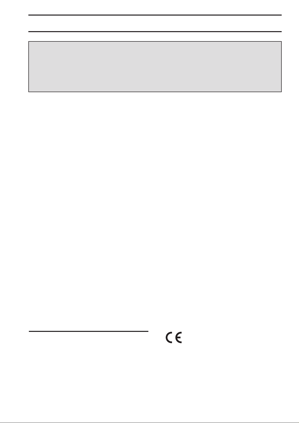
If you cannot light the flame even after several attempts,
check the "cap" (Fig. 1 lett. A) and the "crown" (Fig. 1 lett.
B) are in the correct position.
To put the flame out, turn the knob to the symbol ●.
• Always turn the flame down or put it out before
taking the pans off the burner.
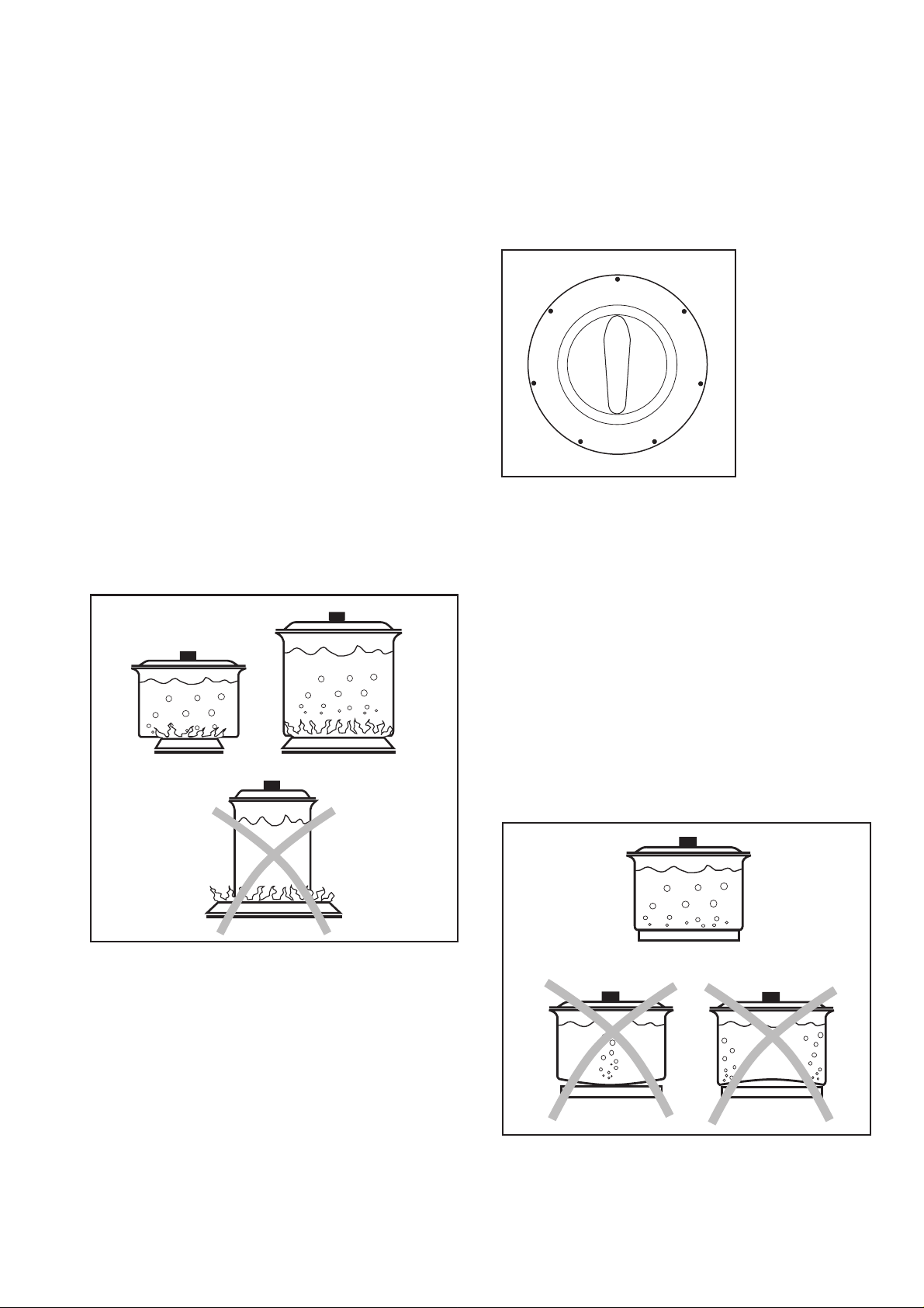
USING THE HOB CORRECTLY
To ensure maximum burner efficiency, it is strongly
recommended that you use only pots and pans with a
bottom fitting the size of the burner used, so that flame
will not spread beyond the bottom of the vessel (see the
table beside).
It is also advisable, as soon as a liquid starts boiling, to
turn down the flame so that it will barely keep the liquid
simmering.
Fig. 1
Burner minimum maximum
FO 0204
diameter diameter
Big (double crown) 160 mm. 260 mm.
Medium (semirapid) 120 mm. 220 mm.
Small (Auxiliary) 80 mm. 160 mm.
3
Page 3
POTTERY
Remember that a wide-bottomed pan allows a faster
cooking than a narrow one.
Always use pots which properly fit what you have to
cook.
Particularly make sure that the pans are not too small
for liquids, since these could easily overflow.
Moreover, the pans should not be too large for a faster
cooking. In fact, grease and juices may spread on the
bottom and burn easily.
It is better to use non-openable moulds for baking
cakes. In fact, an openable mould lets juices and sugar
leak through, falling on the bottom of the oven and
consequently burning on the bottom of the baking tray,
making cleaning difficult.
Avoid putting plastic-handled pans in the oven as they
are not heat-proof.
You should use oans with the right diameter to fit the
burner, in order to make the most out of it, thus
reducing gas consumption as in Fig. 2.
It is also advisable to cover any boiling casserole and,
as soon as the liquid starts boiling, lower the flame
enough to keep the boiling point.
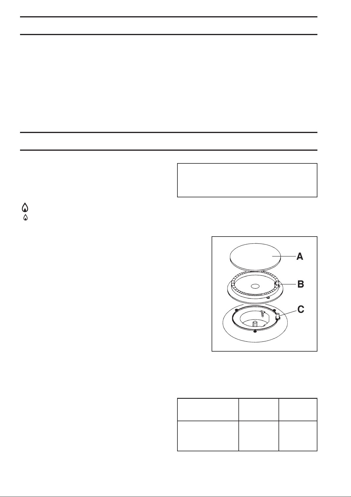
HOTPLATES
The hotplates control knob can be adjusted on six
different positions, according to your cooking needs,
from maximun heat (position 6) to minimum heat
(position 1), as shown in Fig. 3.
0
6
5
4
Saucepans suitable for use on solid plate hobs should
have several characteristics:
• they should be fairly heavy duty;
• they should fit the heat area exactly, or be slightly
larger for efficient use, NEVER smaller;
1
2
3
Fig. 3
Fig. 2
• they should have a flat base to ensure good contact
with the plate (see Fig. 4).
This is particularly important when using pans for high
temperature frying or pressure cooking.
Ensure pans are large enough to avoid liquids being
spilt onto the plates.
Never leave the plates on without a pan on them or with
an empty pan on them.
Fig. 4
4
Page 4

2. Cleaning and Maintenance
• Disconnect the appliance from the electrical
supply, before carrying out any cleaning or
manteinance work.
Wash the enamelled components with warm soapy
water. Never use abrasive cleaners
Frequently wash the "caps" and the "crowns" with hot
soapy water, carefully taking away any built-up of food.
Carefully wash the stainless steel components with
water, then wipe them dry with a soft cloth.
The pan supports are dishwasher proof.
If the marks are particularly difficult to remove, use
common non-abrasive cleaners or specific products.
Never use steel wool pads or acids.
In models provided with electric ignition, this feature is
obtained through a ceramic "candle" and a metal
electrode (fig. 1 lett. C). Keep these components well
clean, to avoid difficult lighting, and check that the
burner crown holes (lett. B) are not obstructed.
PERIODIC MAINTENANCE
Periodically ask your local Service Centre to check the
conditions of the gas supply pipe and the pressure
adjuster, if fitted.
To ensure the good operation of the hob and its safety
features, it is necessary that the taps are periodically
lubricated.
● The periodic lubrication of the taps must be
carried out by qualified personnel, which you
must refer to also in case of malfunctioning.
3. Manteinance - Technical Assistance
ORIGINAL SPARE PARTS
This machine, before leaving the factory, has been
tested and studied by many experts and specialists, in
order to give you the best results.
Any repair work which needs to be carried out should
be done with the utmost care and attention.
For this reason we reccomend that for any problem you
contact the dealer who sold it to you, or our nearest
authorized Service Centre, specifying the nature of the
problem and the particular model which you own.
5
Page 5

4. Technical Data
Gas Burners Rating
Rapid (Double Crown) 3,5 kW
Auxiliary (small) 1 kW
Semirapid (medium) 2 kW
Category II 2H3+
Setting L.P.G. 28-30/37 mbar
Gas connection G 1/2"
5. Instruction for the Installer
Electric Supply 230 V 50 Hz
HOB RECESS
DIMENSIONS
Length 560
Width 480 mm.
mm.(60 cm hob
) - 830
mm.(90 cm hob
)
● The side walls of the unit in which the hob is
going to be installed, must not exceed the height
of the working top.
● Avoid installing the appliance in the proximity of
inflammable materials (e.g. curtains, tea towels
etc.).
● The following instructions about installation and
maintenance must be carried out by qualified
personnel in compliance with the regulation in
force.
● The appliance must be electrically disconnected
before all interventions. If any electric supply to
the appliance is required to carry out the work,
ensure all the necessary precautions are
followed.
A) Ramp with ending nut
B) Seal
C) Adjustable connection
GAS CONNECTION
Choose fixed connections or use a flexible pipe in
stainless steel.
If using flexible metallic pipes, be careful they do not
come in contact with mobile parts or they are not
squeezed. Use the same attention when the hob is
combinated with an oven.
IMPORTANT - To ensure a correct operation, a saving
of energy and the long-life of the appliance, the voltage
pressure of the appliance must correspond to the
recommended values.
The adjustable connection is fixed to the comprehensive
ramp by means of a threaded nut GJ 1/2". Interpose the
sealing between the components as shown in fig. 5.
Screw the parts without forcing, adjust the connection in
the required direction and tighten everything.
IMPORTANT - When the final connection has been
made, it is essential that a thorough leak test is carried
out on the hob and installation. Use some soapy water,
never a flame.
FO 0264
6
Fig. 5
Page 6

6. Electrical Connection
The appliance is designed to be connected to 230 V ~
50 Hz electricity supply.
The connection must be carried out in compliance with
the laws and regulations in force.
Before the appliance is connected:
1) check that the main fuse and the domestic installation
can support the load (see the rating label);
2) check that the power supply is properly earthed in
compliance with the current rules;
3) check the socket or the double pole switch used for
the electrical connection can be easily reached with
the appliance built in the forniture unit.
The appliance is supplied with a connection cable. This
has to be provided with a proper plug, able to support the
load marked on the identification plate. The plug has to
be fitted in a proper socket.
If connecting the appliance directly to the electric system,
it is necessary that you install a double pole switch
between the appliance and the electricity supply, with a
minimum gap of 3 mm. between the switch contacts and
of a type suitable for the required load in compliance
with the current rules.
The connection cable has to be placed in order that, in
each part, it cannot reach a temperature 50 °C higher
than the room temperature.
The manufactures declines all responsibility
should the safety laws and regulations not be
respected.
7
Page 7

7. Adaptation to different types of gas
INJECTORS REPLACEMENT
• Remove the pan supports.
• Remove the burner's caps and crowns.
• With a socket spanner 7 unscrew and remove the
injectors (Fig. 6), and replace them with the ones
required for the type of gas in use (see table 2).
• Reassemble the parts, following the same procedure backwards.
• Replace the rating label (placed near the gas supply
pipe) with the relevant one for the new type of gas
supply. You can find this label in the package of the
injectors supplied with the appliance.
Should the feeding gas pressure be different or
variable compared with the required pressure, an
appropriate pressure adjuster must be fitted on the gas
supply pipe, in compliance with the rules in force.
ADJUSTMENT OF MINIMUM LEVEL
To adjust the minimum level of the burners, proceed as
follows:
Fig. 6
FO 0392
• Light the burner.
• Turn the knob on the minimum position.
• Remove the knob.
• With a thin screwdriver, adjust the by-pass screw
positioned beside or inside the tap rod (see Fig. 7 lett. "a"). If changing from natural gas to LPG,
completely tighten clockwise the screw. When
converting from LPG to natural gas unscrew about
one-fourth turn by-pass pin.
• Finally check the flame does not go out when quickly
turning the knob from the maximum position to the
minimum position.
This procedure can easily be carried out, anyhow the
hob has been positioned or built in the working top.
Table 2 : injectors
BURNER NORMAL REDUCED NORMAL
POWER POWER POWER
Fig. 7
Table 1 : BY-pass diameters
Burner Ø By-pass Tap
Auxiliary 28 Red/Yellow
Semi-rapid 32 Black/Green
Rapid (double-crown) 56 Black/Red
FO 1045
in 1/100 colour
of mm.
kW kW NATURAL GAS LPG
G20 - 20 mbar 28-30/37 mbar
inj. 1/100 m3/h inj. 1/100 g/h
Auxiliary (small) 1 0,33 70 0,095 50 72
Semi-rapid (medium) 2 0,45 96 0,190 71 144
Rapid (double crown) 3,5 1,2 136 0,333 93 252
8
Page 8

8. Building In
A = Auxiliary burner SR = Semirapid burner
R = Rapid Burner (Double crown)
These hobs can be inserted in a built-in kitchen unit
whose depth is between 550 and 600 mm. The hobs
dimensions are shown in Figures 8 to 11.
FO 0940
FO 0244
SR
R
SR
R
580
860
SR
SR
500
A
R
A
500
580
FO 0941
Fig. 9
500
SR
Fig. 8
SR
SR
500
A
R
A
860
FO 0245
Fig. 10
Fig. 11
9
Page 9

INSTALLATION AND ASSEMBLY
830
480
55 min.
30
560
480
55 min.
30
These hobs can be installed in a kitchen unit with an
opening for insertion whose dimensions are shown in
Fig. 12 and 13.
The edge of the cut out must have a minimum distance
from the rear wall of 55 mm.
If there are side walls, or sides of the furniture unit near
the hob, the cut out edges must have a minimum
distance of 100 mm.
Carry out the building in of the hob as follows:
• put the relevant sealings, supplied with the hob, on
the edges of the cut out, taking care that the sealings
meet without overlapping;
• place the hob in the cut out, taking care of its
centring;
• fix the hob with the relevant screws (Fig. 14). The
traction of the screws is able to trace the sealing, any
excess of which can then be easily removed.
The edge of the hob forms a double labyrinth seal
which provides a total guarantee against infiltration of
liquids.
FO 2138
Fig. 12
FO 2101
Fig. 13
10
FO 0199
a) sealing gasket
a
Fig. 14
Page 10

POSSIBILITIES FOR
INSERTION
Fig. 15
Fig. 16
Kitchen unit with door
Proper arrangements must be
taken in designing the forniture
unit, in order to avoid any contact
with the bottom of the hob which
can be heated when it is operated.
The recommended solution is
shown in Fig. 15.
The panel fitted under the hob
should be easily removable to
allow an easy access if a technical
assistance intervention is needed.
Kitchen unit with oven
The hob recess dimensions must
comply the indication given in
Figs. 16 and 19 and must be
provided with brackets to allow a
continuous supply of air.
To avoid overhating, the building
in should be carried out as shown
in Figs. 17 e 18.
The hob's electric connection and
the oven's one must be carried out
separately, both for safety reasons
and to allow the oven to be easily
taken off the unit.
Hanging forniture units or hoods
must be placed at 650 mm.
minimum from the hob (Fig. 20).
30
60
a
20 min
b
FO 1013 FO 2043
a) Removable panel
b) Space possibly useful for
connections
Fig. 17
50 cm
2
Fig. 18
480
380
140
30
591
120 cm
2
Fig. 19
FO 0198
560 min.
550 min.
2
360 cm
FO 0938 FO 0939
Fig. 20
650 mm
FO 2099
180 cm
2
11
 Loading...