

Page 1
MTH 350
Hydraulisch gesteuerter, offener
Klein-Durchlauferhitzer
mit Blankdraht-Heizsystem
Gebrauchs- und Montageanweisung
Deutsch
MTH 350
Hydraulically controlled, open
small-instantaneous water heater
with bare-wire heating system
Operating and Installation instructions
English
Page 2
165
143
190
120
4
5
4,8
6
82
3
MTH 350
MTH 350 mit / with
AHo 40 MTH
7
30
2
1
95
MTH 350
mit / with
AHo 40 MTH
G 3/8
20
n
n
o
MTH 350 mit / with
AHu 40 MTH
MTH 350 mit / with
AHEu 40 MTH
p
MTH 350
mit / with
AHu 40 MTH
q
MTH 350
mit / with
AHEu 40 MTH
120
r
2
Page 3

Deutsch English
Inhaltsverzeichnis
1. Gebrauchsanweisung _________________________ 4
1.1 Gerätebeschreibung _____________________ 4
1.2 Das Wichtigste in Kürze __________________ 4
1.3 Warmwasserleistung _____________________ 4
1.3 Wichtige Hinweise ______________________ 4
1.5 Erste Hilfe bei Störungen _________________ 4
1.6 Wartung und Pflege _____________________ 4
1.7 Gebrauchs- und Montageanweisung ________ 4
2. Montageanweisung __________________________ 5
2.1 Geräteaufbau __________________________ 5
2.2 Liefervarianten _________________________ 5
2.3 Wichtige Hinweise ______________________ 5
2.4 Kurzbeschreibung _______________________ 5
2.5 Armaturen _____________________________ 5
2.6 Vorschriften und Bestimmungen ___________ 6
2.7 Technische Daten _______________________ 6
2.8 Montageort ____________________________ 7
2.9 Gerätemontage _________________________ 7
2.10 Elektrischer Anschluss ____________________ 7
2.11 Erstinbetriebnahme______________________ 8
2.12 Sonderzubehör _________________________ 8
2.12 Störungsbeseitigung _____________________ 9
3. Kundendienst und Garantie __________________ 10
3.1 Entsorgung von Verpackung und Altgerät ____ 11
Table of Contents
1. Operating instructions ______________________ 12
1.1 Unit description _______________________ 12
1.2 The most important points in brief ________ 12
1.3 Hot water output ______________________ 12
1.3 Important notes _______________________ 12
1.5 First actions to be taken in the event
of malfunction ________________________ 12
1.6 Maintenance and care __________________ 12
1.7 Operating and installation instructions _____ 12
2. Installation instructions _____________________ 13
2.1 Unit structure _________________________ 13
2.2 Delivery variants _______________________ 13
2.3 Important information __________________ 13
2.4 Brief description _______________________ 13
2.5 Fittings_______________________________ 13
2.6 Regulations and provisions _______________ 14
2.7 Technical data _________________________ 14
2.8 Installation location ____________________ 15
2.9 Unit installation _______________________ 15
2.10 Electrical connection ___________________ 15
2.11 First start-up __________________________ 16
2.12 Special accessories _____________________ 16
2.12 Fault elimination _______________________ 17
3. Guarantee _________________________________ 18
3.1 Environment and recycling _______________ 18
3
Page 4
For the user and the qualified installer
1. Operating instructions
1.1 Unit description
The MTH hydraulically controlled open (pressureless) small-instantaneous water heater is designed for
supplying an open fitting with hot water. When the draw-off fitting is opened, the heating capacity
switches on automatically and the water is heated. The hot water output is dependent on the cold
water temperature, the heating capacity, and the flow rate.
1.2 The most important points in brief
Temperature adjustment is effected using the fitting:
– To increase the temperature, restrict the flow rate a little.
– For low temperatures, increase the flow rate or mix in cold water.
1.3 Hot water output
Type Output hot water output*
MTH 350 3.5 kW 2.0 l/min
*The built-in automatic flow regulation provides for a constant flow rate. Hot water output with 230 V
mains voltage and a temperature increase of 25 K.
1.3 Important notes
In the case of temperature selection, water temperatures of over 60 °C can be reached at the hot
water outlet. Small children should therefore be kept away from the hot water outlets.
DANGER OF SCALDING!
• If the water feed of the MTH has been interrupted – e.g. because of the danger of frost or work on
the water pipe, the following steps must be taken before the unit is brought back into operation:
1. Remove or switch off fuses.
2. Open a tap downstream of the unit until the unit and the cold water feed pipe are free of air.
3. Replace or switch on fuses again.
• The small-instantaneous water heater must not be exposed to any pressure. Never close off the
fitting outlet and do not use an aerator or a hose with a jet regulator. Furring can close off the outlet
and thus cause the small-instantaneous water heater to be under pressure.
1.5 First actions to be taken in the event of malfunction
• Check the fuses
• Check the fitting for lime scale blockage or dirt accumulation.
See also “3. Fault finding by the user”.
1.6 Maintenance and care
Maintenance work, such as for example checking the electrical safety, may only be carried out by
a qualified installer.
Regularly delime the jet regulator in the fitting and if necessary replace:
Order no.: 25 45 13
A damp cloth is sufficient for care of the unit. Do not use any abrasive or corrosive cleaning agents.
1.7 Operating and installation instructions
Keep these instructions carefully and pass them on to your successor in the event of a change in
ownership, in the event of maintenance and possible repair work they should be passed to the
qualified installer for his attention.
12
Page 5

2. Installation instructions
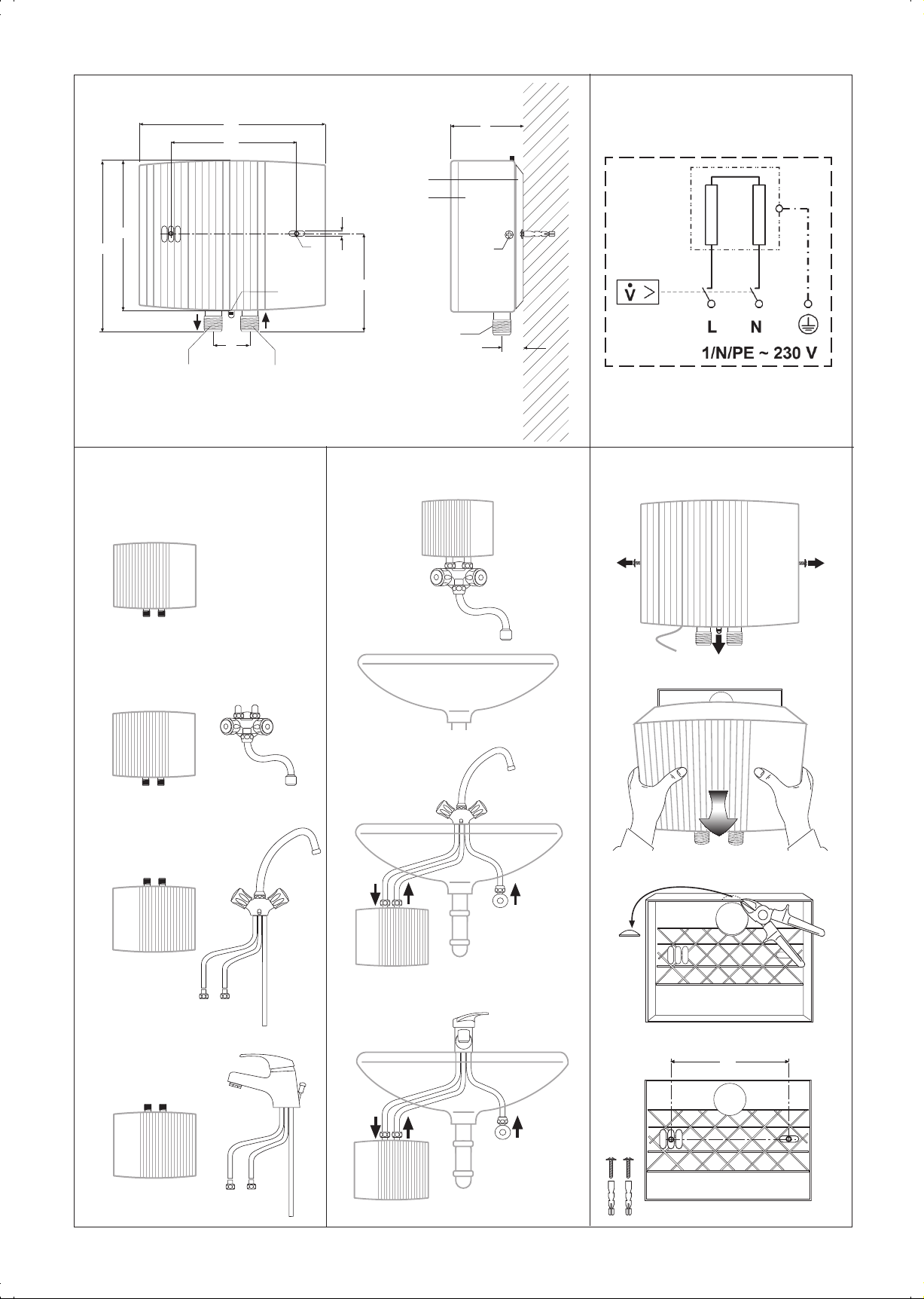
2.1 Unit structure
1 Cold water connection with filter
2 Hot water connection
3 Cover securing screw
4 Unit rear panel
5 Unit front cover
6 Fixing holes for under-sink installation
7 Snap closing catch
2.2 Delivery variants
MTH 350
MTH 350 with AHo 40 MTH
MTH 350 with AHu 40 MTH
MTH 350 with AHEu 40 MTH
For the qualified installer
English
2.3 Important information
Air in the cold water pipe will destroy the bare-wire heating system of the MTH.
If the water supply to the MTH has been interrupted, for example due to the risk of frost or work
on the water pipe, the following steps must be carried out before the system is used again:
1. Disconnect supply or disconnect the fuses.
2. Open a hot water tap downstream of the device for as long as is necessary for the device and the
cold water pipe to be freed of air.
3. Reconnect the supply or connect the fuses again.
All information in these Instructions for Use and Installation must be followed carefully. They provide
important information with regard to safety, operation, installation, and maintenance of the device.
2.4 Brief description
The MTH hydraulically controlled small-instantaneous water heater is a pressureless unit for the
heating of cold water in accordance with WRC Regulations, with which a water tap can be supplied.
The unit is suitable for hand washing basins, for example in guest WC’s, and for under-sink and
over-sink installation.
The bare-wire heating system is suitable for low-lime and limy water (see Table 2 for ranges of use).
2.5 Fittings
Only pressureless fittings may be installed. The MTH must not be exposed to any pressure. Never close
off the fitting outlet. Furring can close off the outlet and impair the function. For optimum jet patterns
use only the jet regulator supplied.
13
Page 6

For the qualified installer
2.6 Regulations and provisions
• Installation (water and electrical installation), as well as the first start-up and maintenance of this
unit, may only be carried out by a qualified installer in accordance with these instructions.
• Faultless operation and operational safety are only guaranteed if the original accessories and spare
parts intended for the unit are used.
• In accordance with IEE and WRC Regulations.
• Regulations of the local energy supply company.
• Regulations of the relevant water supply company.
The following should also be observed:
• The unit rating plate.
• Technical data (see Table 1).
The specific electrical resistance of the water must not be lower than specified on the rating
plate. In the case of a water grid supply network, the lowest electrical resistance of the water is
to be taken into account (see Table 2). Your water supply company will advise you of the
specific electrical resistance or the electrical conductivity of the water.
Water installation:
• A safety valve is not necessary.
• Operating the unit with preheated water is not permitted!
• Fittings for pressurised units are not permitted!
Electrical installation:
• It must be possible to isolate the unit from the main supply on all poles with an isolating distance of
at least 3 mm, for example using fuses.
2.7 Technical data (the data on the unit identification plate are applicable)
Type MTH 350
Rated power 3.5 kW
Rated voltage 230 V ~
Rated current 15 A
Hot water output ∆ϑ = 25 K 2.0 l/min
Flow rate „on“ ≤ 2.0 l/min
Flow rate „off“ ≥ 0.9 l/min
Automatic flow regulation 2.2 l/min
Pressure drop (during switch-on flow) 0.05 MPa
Max. inlet temperature 25 °C
Rated capacity 0.1 l
Design open
Weight 1.4 kg
Protection class in accordance with EN 60335 1
Protection mode in accordance with EN 60529 IP 25
Test mark See unit identification plate
Structural inspection test certificate PA-No. (Nr. for Germany)
Water connections (external thread) G 3/8, surface installation
Electrical connection 1/N/PE ~ 230 V
Heating system Bare-wire
Area of use Low-lime and limy water
Range of use with regard to specific
electrical resistance / conductivity See Table 2
14
Table 1
Page 7

For the qualified installer
Areas of application for instantaneous water heaters relative to the specific electrical
conductivity / specific electrical resistance of the water
Designation as Areas of application for different water analysis
reference temperatures* designation
Standard at at
at 15 °C 20 °C 25 °C
Specific electrical resistance ≥ 1100,9 Ωcm ≥ 1970 Ωcm ≥ 1900 Ωcm
corresponding to
specific electrical conductivity ≤ 1190.9 mS/m ≤ 1103 mS/m ≤ 1111 mS/m
≤ 1909,9 µS/cm ≤ 1030 µS/cm ≤ 1110 µS/cm
Table 2
* The values for the specific electrical resistance and the specific electrical conductivity are determined
at different temperatures in different regions. This must be taken into account in the evaluation.
2.8 Installation location
The MTH is to be installed, according to choice, as an over-sink or under-sink unit ,
in a closed, frost-free room in the vicinity of the water tap (dismantled unit is to be stored
in a frost-free place, as residual water always remains in the unit).
2.9 Unit installation
Under-sink installation with AHu 40 MTH or AHEu 40 MTH fitting
n Loosen cover securing screws by two turns.
o Using a screwdriver, release the snap closing catch.
p Take off the unit front cover with heating block.
q With the help of a pair of nippers, break out the feed-through opening for the connection cable
(break-off point).
r Fix the unit rear panel to the wall using dowels and screws; use the unit rear panel as a drilling
template.
Installation, last in – first out.
Screw connecting hoses of the AHu 40 MTH or AHEu 40 MTH unit onto the water connections (1 and 2)
(see fittings description), when doing this use a 14 mm spanner on the unit as a counter-force.
Over-sink installation with AHo 40 MTH fitting
The cold water pipe and AHo 40 MTH wall fitting must be safely secured.
1. Screw the AHo 40 MTH wall fitting into the wall disc.
2. Screw the MTH unit onto the fitting; when doing this use a 14 mm spanner on the unit as a
counter-force.
English
Over-sink installation without wall fitting
Installation of the unit as shown in illustration (Gerät um 180 ° gedreht).
2.10 Electrical connection
The unit must be connected to the protective earth terminal.
• This appliance is fitted with a power supply cabel.
15
Page 8

For the qualified installer
2.11 First start-up
(may only be carried out by a qualified installer)
n
ON
EINEIN
EIN
EINEIN
o
ON
n Fill and deaerate the unit. Note: danger of running dry!
Open and close the tap repeatedly until the pipework and the unit are free of air. For guidance on
air, see „2.3 Important information“.
o Switch on the mains power.
p Test the operating mode of the instantaneous water heater and armature.
Note: the enclosed sticker has to be stucked after unit installation
Handover of the unit
Explain the function of the unit to the user and familiarize him or her with its use.
Important instructions:
• Draw the user’s attention to possible hazards (scalding).
• Hand over these instructions for careful retention.
2.12 Special accessories
• Wall fitting, pressureless, for MTH
• Twin-handle washstand fitting, pressureless, for MTH
• Single lever washstand fitting, pressureless, with pull rod drain for MTH
• Jet regulator for AHo 40 MTH, AHu 40 MTH, AHEu 40 MTH fitting
16
Page 9

2.12 Fault elimination
For the user and the qualified installer
Fault
Fault elimination by the user
No hot water despite fully
opened hot water fitting.
Fault elimination by the qualified installer
Flow too weak.
Heating fails to switch on /
no hot water.
Cause
• No electrical power.
• The turn on flow rate needed
to switch on the heating
power has not been reached.
Soiling or furring of the jet
regulator.
• Jet regulator furred or soiled.
• Filter soiled.
• No electrical power.
Remedy
• Check the fuses in the house
installation.
• Clean or if necessary renew
the jet regulator (see „2.12
Special accessories“).
English
• Clean or if necessary renew the
fitting jet regulator (see „2.12
Special accessories“).
• Clean the filter in the cold
water inlet (1) after shutting
off the water supply.
• Check the fuse
(house installation).
• Heating system defective.
• Measure heating system
resistance, if necessary
exchange the unit.
17
Page 10

For the user and the qualified installer
3. Guarantee
For guarantee please refer to the respective terms and conditions of supply for your country.
The installation, electrical connection and first operation of this appliance should be carried out
by a qualified installer.
The company does not accept liability for failure of any goods supplied which are not installed in
accordance with the manufacturer's instructions.
3.1 Environment and recycling
Please help us to protect the environment by disposing of the packaging in accordance with the
national regulations for waste processing.
18
Page 11

Adressen und Kontakte
Vertriebszentrale
EHT Haustechnik GmbH
Markenvertrieb AEG
Gutenstetter Straße 10
90449 Nürnberg
info@eht-haustechnik.de
www.aeg-haustechnik.de
Tel. 0 18 03 / 91 13 23
Fax 09 11 / 96 56 - 44 4
Kundendienstzentrale
Holzminden
Fürstenberger Str. 77
37603 Holzminden
Briefanschrift
37601 Holzminden
Der Kundendienst
und Ersatzteilverkauf
ist in der Zeit von
Montag bis Donnerstag
von 7.15 bis 18.00 Uhr
und Freitag
von 7.15 bis 17.00 Uhr,
auch unter den
nachfolgenden Telefon- bzw.
Telefaxnummern erreichbar:
Kundendienst
Tel. 0 18 03 / 70 20 20
Fax 0 18 03 / 70 20 25
Ersatzteilverkauf
Tel. 0 18 03 / 70 20 40
Fax 0 18 03 / 70 20 45
Regionen
AEG Kundendienst
Dortmund
Oespel (Indupark)
Brennaborstr. 19
44149 Dortmund
Postfach 76 02 47
44064 Dortmund
Tel. 02 31 / 96 50 22-11
Fax 02 31 / 96 50 22-77
Frankfurt
Rudolf-Diesel-Str. 18
65760 Eschborn
Tel. 0 61 73 / 6 02-11
Fax 0 61 73 / 6 02-77
Hamburg
Georg-Heyken-Str. 4a
21147 Hamburg
Tel. 0 40 / 75 20 18-11
Fax 0 40 / 75 20 18-77
Holzminden
Fürstenberger Str. 77
37603 Holzminden
Ersatzteile
Tel. 0 55 31 / 7 02-1 37
Fax 0 55 31 / 7 02-3 35
Kundendienst
Tel. 0 55 31 / 7 02-111
Fax 0 55 31 / 7 02-1 07
Leipzig
Airport Gewerbepark-Glesien
Ikarusstr. 10
04435 Schkeuditz
Tel. 03 42 07 / 7 55-11
Fax 03 42 07 / 7 55-77
Ausland
Schweiz
EHT Haustechnik AG
Industriestrasse 10
CH-5506 Mägenwill
Tel. 0 62 / 8 89 92 14
Fax 0 62 / 8 89 91 26
Nederland
AEG Home Comfort
Daviottenweg 36
NL-5222 BH's
Hertogenbosch
Tel. 0 73 / 6 23 00 00
Fax 0 73 / 6 23 11 41
Belgium
AEG Home Comfort
Havenlaan – Av. du port, 104
B-1000 Brussel – Bruxelles
Tel. 02 / 4 22 25 22
Fax 02 / 4 22 25 24
Czech Republic
Stiebel Eltron Czech
K Hájum 946
CZ-Prague 5 - Stodulky
Tel. 0 04 20 / 251 11 61 11
Fax 0 04 20 / 235 51 21 22
Polska
Stiebel Eltron Polska Sp. z o.o.
Ul. Instalatorów 9
02-237 Warszawa
Tel. 0 22 / 8 46 48 20
Fax 0 22 / 8 46 67 03
München
Martinsried
Bunsenstr. 7
82152 Planegg
Tel. 0 89 / 89 91 56-11
Fax 0 89 / 89 91 56-77
Stuttgart
Weilimdorf
Motorstr. 39
70499 Stuttgart
Tel. 07 11 / 9 88 67-11
Fax 07 11 / 9 88 67-77
19
Page 12

EHT Haustechnik GmbH
Markenvertrieb AEG
Gutenstetter Straße 10
D-90449 Nürnberg
GERMANY
www.aeg-haustechnik.de
info@eht-haustechnik.de
EHT-Haustechnik GmbH
255661/33604/1/7939 · WI · Technische Änderungen vorbehalten · Subject to technical modifications
 Loading...