

Page 1
Page 2
TOOLS AND
MATERIALS REQUIRED (continued)
PLAN DUCTWORK
INSTALLATION (continued)
For Ductfree Installations Only:
❏ One two-pack HF88 Replacement Filter Kit
For Installation On Kitchen Cabinets With Recessed Bottoms
Only:
❏ Two 1” x 2” x 12” (approximate length) wood strips (purchase
locally)
❏ Four 1-1/4” long flat head wood screws (purchase locally)
to fasten strips to cabinet bottom
PLAN DUCTWORK INSTALLATION
For Ducted Installations Only:
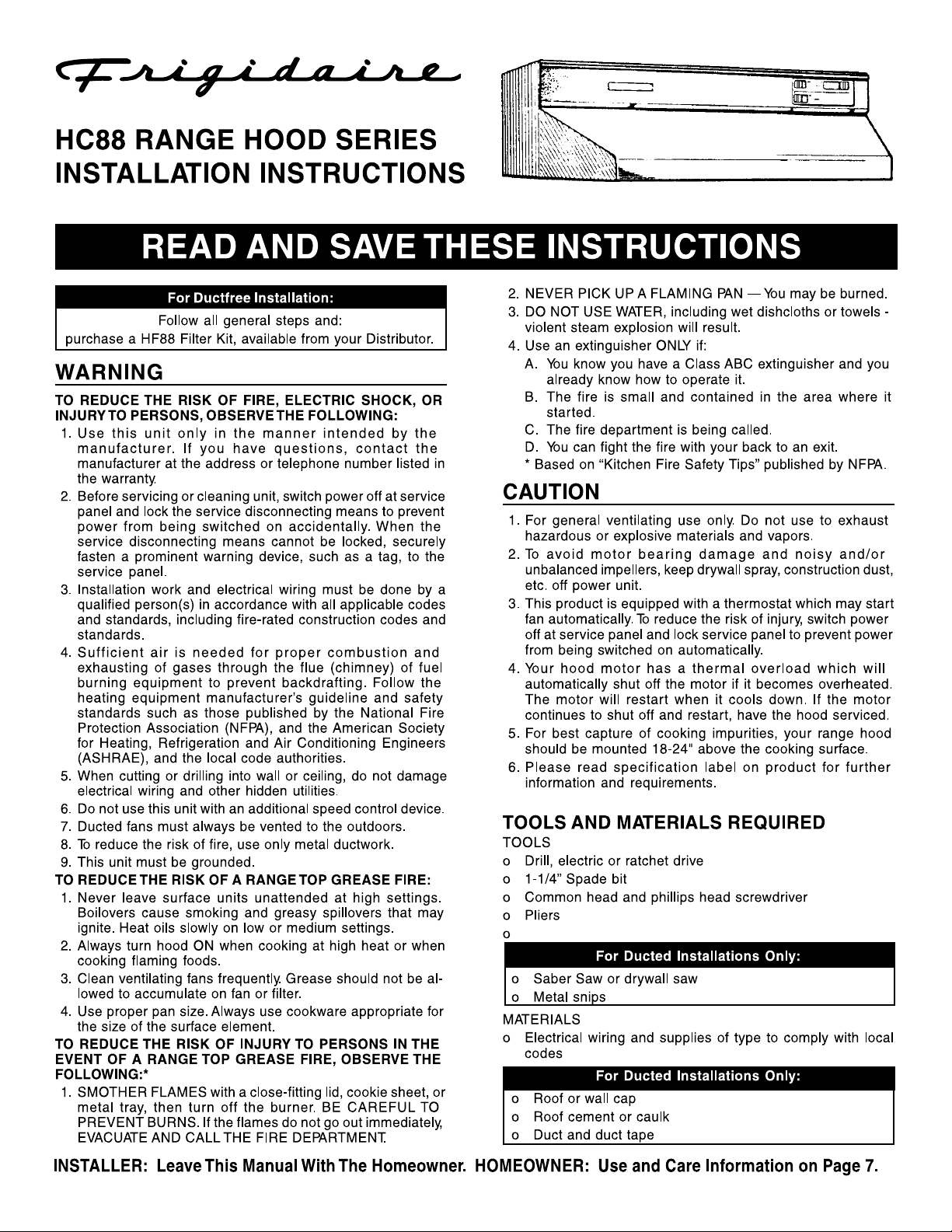
Begin planning ductwork by deciding where duct will run
between hood and outside. For best performance, use
shortest possible duct run and a minimum number of elbows.
In more complex situations, 3-1/4” x 10” duct can be
converted to round duct by means of a transition. FIGS 1A 1E show several choices.
FIG. 1C
ROOF CAP
3-1/4" X 10" DUCT
FIG. 1C: Ducting straight up through roof using 3-1/4” x 10”
duct. For single story installations.
FIG. 1D
ROOF CAP
FIG. 1A
WALL CAP
FIG. 1A: Ducting directly through outside wall. If wall cap is
used directly off back of hood, check to make sure that
damper flap in damper/duct connector on hood does not
interfere with damper flap in wall cap. If it does, remove flap
on hood damper/duct connector.
FIG. 1B
ELBOW
3-1/4" X 10" DUCT
WALL
CAP
6" ROUND DUCT
3–1/4" X 10" TO 6"
ROUND DUCT
TRANSITION
FIG. 1D: Straight up through roof using round duct.
FIG. 1E
ADJUSTABLE ELBOW
3–1/4" X 10" TO 6"
ROUND DUCT
TRANSITION
6" ROUND
DUCT
WALL CAP
FIG. 1B: At times it will be easier to run duct vertically and
use an elbow.
FIG. 1E: Ducting between ceiling joists for multi-story
installations or through soffits above cabinets where soffit
2
connects to outside walls.
Page 3
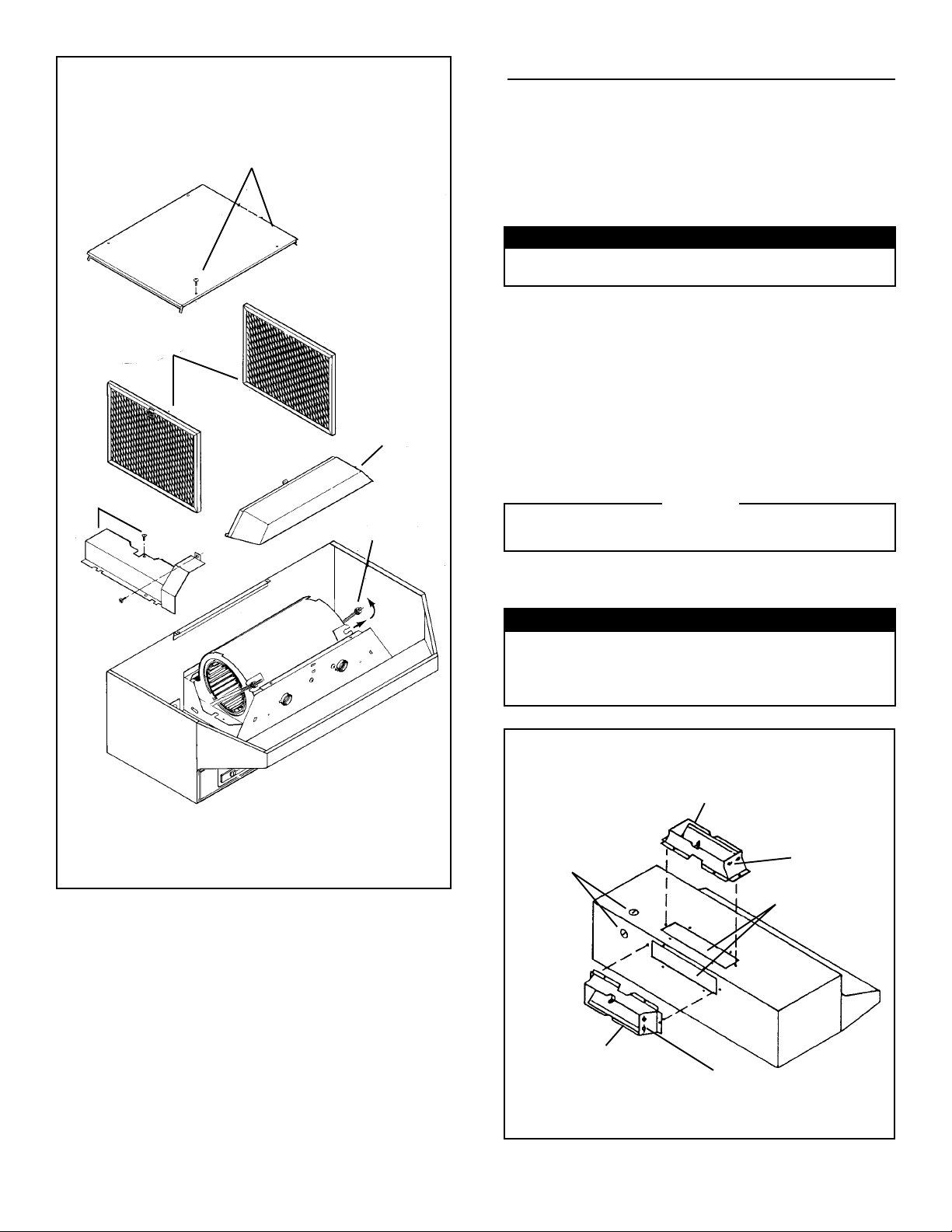
FIG. 2
STEP 4
STEP 3
STEP 2
STEP 6
STEP 5
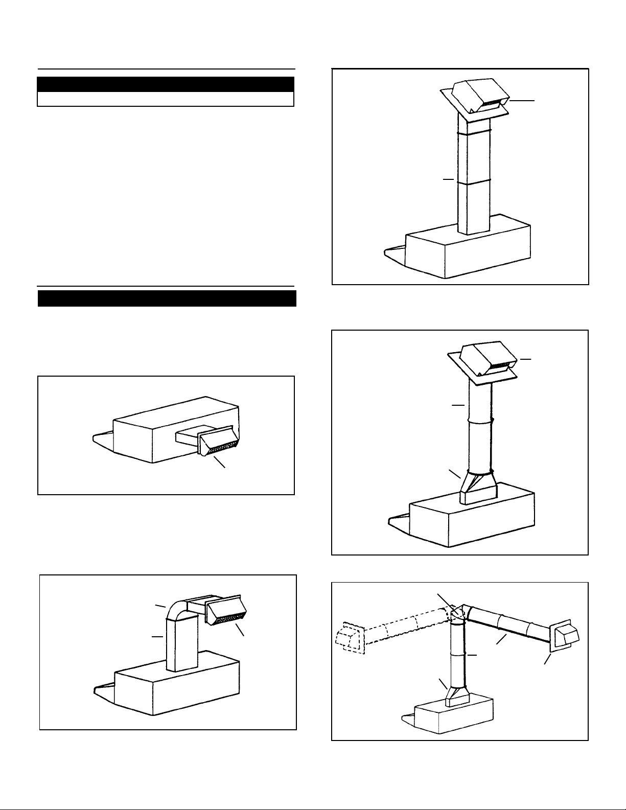
PREPARE HOOD
1. Unpack hood and check contents. You should receive:
1 - assembled hood
1 - plastic bag, containing:
4 - 7/8” wood screws for mounting hood to cabinet
2 - 1/4” black sheet metal screws for mounting damper/
duct connector to hood
2 - aluminum filters
1 - damper/duct connector
For Ductfree Installations Only:
Discard damper/duct connector and two black sheet metal
screws.
For Steps 2 - 6 below, refer to FIG. 2.
2. Set hood upside down and remove bottom cover and
screws.
3. Remove filters.
4. Remove wiring box cover and screws.
5. To make hood lighter and easier to handle, remove blower
assembly.
a.) Unplug blower.
b.) Loosen knurled nuts on mounting rods and slip rods
out of blower mounting brackets. Do not remove nuts
completely from rods.
c.) Lift out blower and set blower aside.
CAUTION
DO NOT GRASP BLOWER BY BLOWER WHEELS.
WHEELS MAY BE DAMAGED.
6. Remove light lens. Squeeze sides of lens toward center of
hood and lift lens out.
7. Remove either top or rear electrical knockout. (FIG. 3)
For Ducted Installations Only:
7. Remove either top or rear duct knockout. (FIG. 3)
Fasten damper/duct connector to hood over opening.
Use two black sheet metal screws provided in parts bag.
(FIG. 3)
FIG. 3
VERTICAL DUCTING*
ELECTRICAL
KNOCKOUTS
HORIZONTAL DUCTING*
HINGE
PINS
* FOR DUCTED INSTALLATIONS ONLY.
3
HINGE
PINS
DUCT
KNOCKOUTS*
Page 4

PREPARE THE
INST ALLA TION LOCA TION
NOTE
IF DISTANCE BETWEEN W ALL AND FRONT OF CABINET
FACE FRAME IS MORE THAN 12”, THERE WILL BE A
GAP BETWEEN BACK OF HOOD AND WALL. THIS IS
NORMAL. TOP FRONT EDGE OF HOOD SHOULD BE
FLUSH WITH FRONT OF CABINET FACE FRAME. OMIT
STEP 1 IF HOOD WILL BE INST ALLED UNDER CABINETS
WITH FLUSH BOTTOM.
1. For Cabinets With Recessed Bottoms ONLY: (FIG. 4)
Install wood filler strips on each side of recessed area under
cabinet. Use two 1” x 2” strips cut to length (use thicker
strips if necessary). Fasten strips with wood screws about
3” in from each end.
2. Measure and mark the following: (FIG. 5)
a.) electrical wiring opening
For Ducted Installations Only:
b.) duct opening
3. Cut duct opening in wall or cabinet bottom.
4. Drill 1-1/4” electrical wiring opening in wall cabinet bottom.
5. Hold hood up against cabinet bottom and trace keyhole
slots onto cabinet bottom or filler strips. For larger hoods:
Two ¼" dia. holes are provided for secure mounting. They
are located in top of hood approx. 8” each side of center.
Add filler strips for these as necessary . A void blocking hood’s
vertical electrical knockout.
6. Screw four 7/8” wood screws from parts bag into exact
center of narrow end of keyhole slots marked on cabinet
bottom. Allow 3/8” of screws to project, so hood can be
fitted into place later.
7. Run electric wiring through hole drilled in wall or cabinet.
Provide 6” leads and install proper connector for type of
wire used.
FIG. 4
CUT STRIPS TO FIT
DUCT
OPENINGS*
WIDTH OF RANGE
HOOD
* FOR DUCTED INSTALLATIONS ONLY.
CENTER
LINE
3"
ELECTRICAL
WIRING
OPENING
3"
FIG. 5
1–1/2"
HORIZONTAL DUCT OPENING
FRONT OF CABINET
3–7/8"
3/8"
6–1/4"
CABINET BOTTOM
6-7/8"
9"
10-5/8"
6–1/4"
BACK WALL
6–1/4"
6–1/4"
1/8"
7–1/2"
7–1/2"
3/4"
1–1/2"
9–7/8"
9"
VERTICAL DUCT OPENING
4
Page 5

INSTALL THE DUCTWORK
For Ducted Installations Only:
NOTE
THESE INSTRUCTIONS WILL FOLLOW THE PLANS
MADE ON PAGE 2. START ON THE OUTSIDE AND
WORK BACK TOWARD HOOD. FOLLOW
APPROPRIATE DIRECTIONS FOR TYPE OF DUCT
SYSTEM YOU ARE INSTALLING.
FIG. 6
WALL CAPS (FIG. 6)
Use a saber saw to cut a hole slightly larger than duct so
duct will line up easily with hood. Install casing strips on
outside walls finished in siding. Assemble the ductwork and
tape all joints. Run ductwork back to hood. Fasten wall cap
to last section of duct and nail or screw cap to wall. Seal all
around flange on wall cap with caulking compound. Make
sure that enough duct runs into the room so that the duct
will overlap the damper/duct connector by 3/4” when the
hood is installed.
FIG. 7A
FIG. 7B
INSTALL HOOD
1. Position hood so that: (FIG. 8)
FIG. 8
ELECTRICAL LINE
a.) electrical wiring runs through opening in top or back of
hood.
b.) large part of keyhole slots fit over hood mounting screws
For Ducted Installations Only:
c.) damper/duct connector slides into ductwork.
2. Push hood back so that mounting screws slide into narrow
end of keyhole slots. When mounting larger hoods, run (2)
screws through the 1/4” dia. holes (in hood top and 8” each
side of center) and into the cabinet bottom or added filler
strips. Tighten all screws firmly.
3. Install locknut on electrical connector and tighten securely.
4. Make electrical connections. Connect white to white, black
to black, and green or bare wire to green ground screw.
(FIG. 9)
3/4"
PLASTIC ROOF
CEMENT
FIG. 7C FIG. 7D
DO NOT CAULK AROUND BOTTOM
OF FLANGE FOR DRAINAGE
NAIL
ROOF CAPS (FIGS. 7A - 7D)
Cut hole in roof slightly larger than duct so duct will line up
easily with hood. Trim shingles around hole so that they will
fit snugly around hood of cap when cap is installed. Assemble
the ductwork and tape all joints. Run the ductwork down to
hood. Trim duct parallel to roof pitch, leaving 3/4” of duct
projecting above roof (FIG. 7A). Seal all around duct with
roof cement. (FIG 7B) Install roof cap, inserting back edge
of cap under shingles. (FIG 7C) Seal around roof cap with
roof cement and seal all nail heads and shingles which were
cut or lifted. (FIG. 7D)
Make sure that enough duct runs into the room so that the
duct will overlap the damper/duct connector by 3/4” when
the hood is put into place.
FIG. 9
BLACK
BLACK
WHITE
WHITE
BLACK
WHITE
GREEN
GROUND
(BARE OR
GREEN WIRE)
GREEN
WHITE
BLACK
5. Replace wiring box cover and screws. Make sure that wires
are not pinched between cover and hood.
6. Install two 75 watt max. bulbs, or one 75 watt bulb and one
25 watt bulb for night-light use. Install 25 watt bulb in righthand socket.
5
Page 6

INSTALL HOOD (Continued)
INST ALL HOOD (Continued)
For Ducted Installations Only:
FIG. 10
BLOWER DISCHARGE
VERTICAL DUCTINGHORIZONTAL DUCTING
7. Reinstall blower. Do not grasp blower by blower wheels.
Position blower so that blower discharge lines up with
damper/duct connector and slip rods into mounting brackets on blower assembly. (FIG. 10) Tighten knurled nuts
securely, and plug in blower.
For Ductfree Installations Only:
FIG. 11
BLOWER
DISCHARGE
LOUVER COVER
For Ductfree Installations Only:
9. Snap aluminum filter onto front of replacement filter. (FIG.
13) Make sure that tab on aluminum filter lines up with
finger pull on replacement filter.
FIG. 13
Push filter assembly into hood. Flaps on filter will flex
against top and sides of opening. (FIG. 14) Push
assembly up until bottom of assembly clears lip on bottom
cover. Insert bottom of filter and pull assembly down,
collapsing pull ring against aluminum filters.
7. Reinstall blower. Do not grasp blower by blower wheels.
Move blower mounting rods to front holes in hood support
channels. (FIG. 11) Position blower so that blower
discharge lines up with louvered opening on hood front.
Slip rods into mounting brackets and tighten knurled nuts
securely. Plug in blower.
Remove louver cover on control panel. Pry cover off with
screwdriver or knife.
8. Reinstall bottom cover and screws. See FIG. 2.
For Ducted Installations Only:
FIG. 12
3
2
FIG. 14
3
2
1
1
9. Reinstall aluminum filters. Make sure tabs are toward
outside and bottom. (FIG. 12)
10. Turn on power and check operation of hood.
6
Page 7

USE AND CARE
CONTROLS (FIG. 15)
FIG. 15
BLOWER - "SPEED"
Infinite speed slide control adjusts blower speed and sound
level for quiet operation
BLOWER - "ON"
Turns blower ON and OFF.
When this control is turned ON, blower will operate at preset
speed of slide control.
LIGHT
Three-position switch
• First position (Normal) - Turns both bulbs ON.
• Second position (Night Light) - Turns right-side bulb ON.
• Third position (OFF) - Turns both bulbs OFF.
DO NOT install bulbs rated higher than 75 watts.
Install a smaller bulb on the right for a night light.
USE AND CARE (Continued)
HOW TO AVOID A COMMON RANGE-TOP GREASE FIRE
• Your range hood provides a protective barrier between
the cooking surface and the cabinets.
• Keep fan, filters and grease laden surfaces CLEAN
according to instructions.
• Always turn hood ON when cooking at high heat to keep
the cooking area and the hood cooler.
• Use high heat settings only when necessary.
• Never leave cooking surface unattended. Boil-over
causes smoking and greasy spillovers that may ignite.
• Always use adequate-sized utensils.
• If preparing flaming foods, such as Cherries Jubilee,
always turn hood ON to HIGH to prevent a high heat
situation which can cause damage or fire.
HOW TO EXTINGUISH A COMMON RANGE-TOP
GREASE FIRE
• Never pick up a flaming pan. If dropped, flames can
spread quickly.
• DO NOT USE WATER! A violent steam explosion may
result. Wet dishcloths or towels are also dangerous.
• Smother flames with a close fitting lid, cookie sheet or
metal tray.
• Flaming grease can also be extinguished with baking
soda or a multi-purpose dry chemical extinguisher.
• Turn off surface units - If you can do so without getting
burned.
HEAT SENTRY™
Your hood is equipped with a Heat Sentry™ thermostat. This
thermostat is a device that will turn on or speed up the blower
if it senses excessive heat above the cooking surface.
1) If blower is OFF - it turns blower ON to HIGH speed.
2) If blower is ON at a lower speed setting - it turns blower up
to HIGH speed.
When the temperature level drops to normal, the blower will
return to its original setting.
FILTER CARE
Remove each filter by grasping the tab at the bottom of filter,
lifting up and swinging filter out to the side.
ALUMINUM FILTERS
Clean filters frequently in a detergent solution. They are
dishwasher safe.
REPLACEMENT
FILTERS
The aluminum filter is the only washable part of the filter system.
Snap it out of its frame and clean it in a detergent solution or
dishwasher.
The particle filter is not washable. It should last up to twelve
months with normal use.
CLEANING
Do not allow an excessive accumulation of grease. Use a mild
detergent suitable for painted surfaces. DO NOT USE
ABRASIVE CLOTH, STEEL WOOL PADS, OR SCOURING
POWDERS. Vacuum blower to clean. Do not immerse blower
in water.
WIRING DIAGRAM
NOTE: If any of the original wire on the hood has to be replaced,
use wire having equivalent insulation and temperature rating
(105°C Thermoplastic AWM, U.L. Listed).
GREEN
6
WHITE
BLACK
WHITE
WHITE
BLACK
ORANGE
BLACK
BLACK
YELLOW
BLACK
CONTROL
BOARD
(SYMBOLIC)
WHITE
M
B
1
2
4
5
8
9
10
120 VAC
LINE IN
WHITE
LAMP "B"
WHITE
THERMOSTAT
BLACK
WHITE
LAMP
"A"
7
Page 8

 Loading...