

Grill Assembly
Built-In Instructions
4-8
9-11
17-18
12-15
13
16
19
44”
Gallery Series

Welcome & Congratulations
Please record Grill information for future reference and service work:
Model #:
Serial #:
Date of Purchase:
Gas Type:
Please retain this manual for future reference
© 2004 Electrolux Home Products, Inc All rights reserved
Congratulations on your purchase of a new gas grill! At Electrolux Home Products, we
are very proud of our product and are completely committed to providing you with the
best service possible. Your satisfaction is our number one priority.
We know you’ll enjoy your new gas grill and Thank You for choosing our product. We
hope you consider us for future purchases.
PLEASE CAREFULLY READ AND SAVE THESE INSTRUCTIONS
This Use & Care Manual provides specific operating instruction for your model. Use your
gas grill only as instructed in this manual. These instructions are not meant to cover every
possible condition and situation that may occur. Common sense and caution must be
practiced when installing, operating and maintaining any appliance.
Questions? 1-800-320-0859
1
TESTED IN ACCORDANCE WITH ANSI
Z21.58b-2002/CGA 1.6b-M02 STANDARD FOR
OUTDOOR COOKING GAS APPLIANCES.
THIS GRILL IS FOR OUTDOOR USE ONLY.
Check your local building codes for the proper
method of installation. In the absence of local
codes, this unit should be installed in accordance
with the National Fuel Gas Code No. Z223.1-2002
and the National Electrical Code ANSI/NFPA No.
70-1990
WARNING
DO NOT try lighting this appliance without reading
the “LIGHTING INSTRUCTIONS” section of this
manual.
FOR YOUR SAFETY
DO NOT store or use gasoline or other flammable vapors and
liquids in the vicinity of this or any other appliance.
An LP cylinder not connected for use shall not be stored
in
the vicinity of this or any other appliance.
2
General Safety Instructions
IMPORTANT SAFETY INFORMATION
-
Read this manual carefully before using your grill to reduce the risk of fire, burn hazard or
other injury.
- Extreme care should be used because of the high temperatures produced by this appliance. CHILDREN SHOULD NOT BE LEFT
UNATTENDED IN AN AREA WHERE THE GRILL IS BEING OPERATED.
- This appliance must be kept clear from combustible materials, gasoline or other flammable vapors and liquids. Do not allow
flammable materials to come in contact with grate, burner or hot surfaces.
- Do not repair or replace any part of this appliance unless it is specifically recommended in this manual. A qualified service technician should conduct all other service.
- Follow the installation and servicing instructions provided with this product. Have your grill installed by a qualified service technician. Locate the main gas supply valve so that you know how to shut the gas off to your grill. If you smell gas, make sure all gas
connections are tight before operation. If you continue to smell gas call a qualified technician.
- When lighting a burner, always pay close attention to what you are doing. Be certain you are pushing the ignitor that lights the
burner you intend on using.
FOR YOUR SAFETY
If you smell gas:
1. Shut off gas to the appliance.
2. Extinguish any open flames.
3. Open lid.
4. If odor continues, immediately
call your gas supplier.
FOR OUTDOOR USE ONLY
This appliance is not intended to be
installed in or on recreational vehicles or boats.
CALIFORNIA PROPOSITION 65 - WARN-
ING: The Burning of gas cooking fuels generates
some by products which are on the list of substances
which are known by the State of California to cause
cancer or reproductive harm. California law requires
businesses to warn customers of potential exposure to
such substances. To minimize exposure to these substances, always operate this unit according to the use
and care manual, ensuring you provide good ventila-
tion when cooking with gas.
3
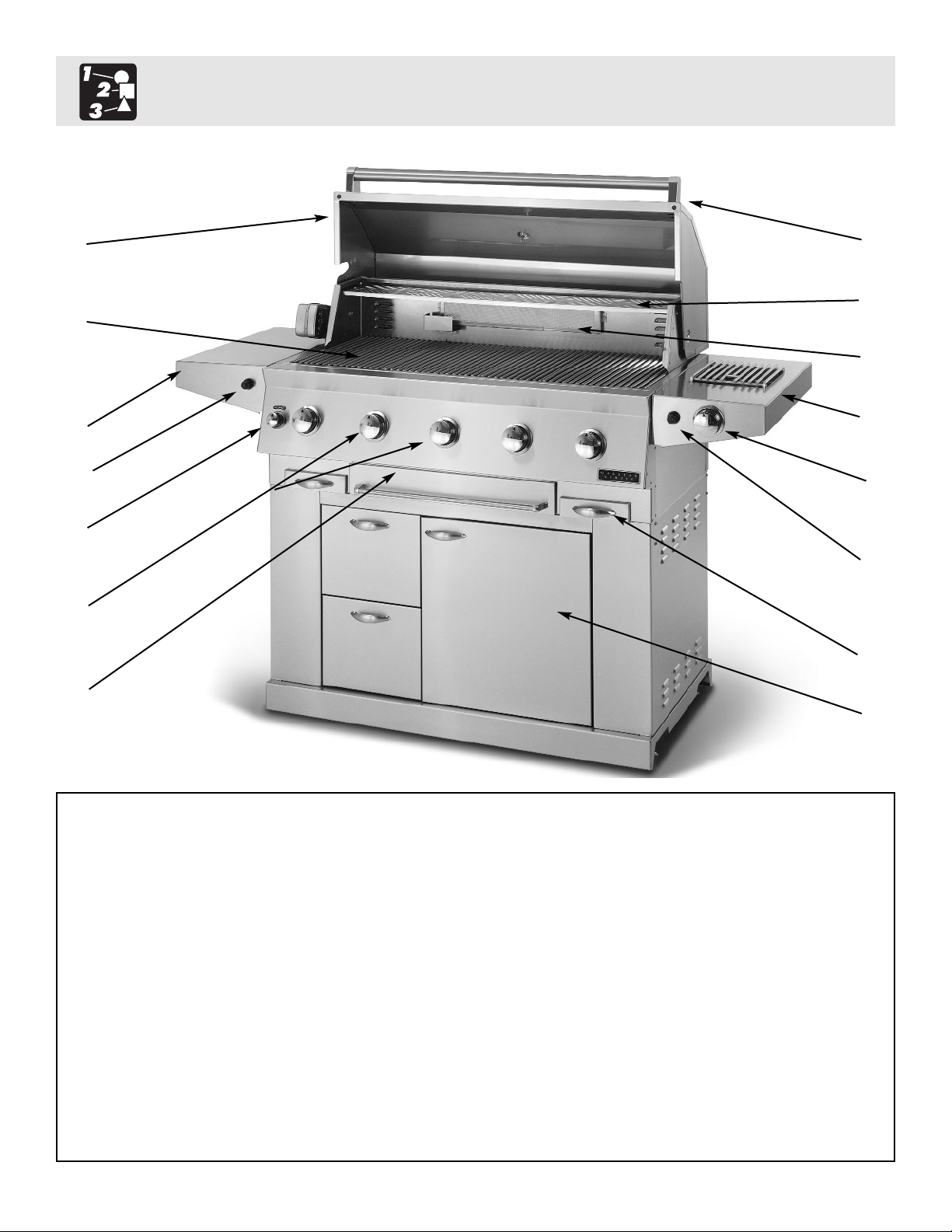
1. Roll top grill hood 8. Warming shelf
2. Grilling/Cooking surface 9. Infrared back burner
3. Side Shelf 10. Electronic ignitors: main, rear infrared
& side burner
4. Control knob: back infrared burner 11. Cart w/doors
5. Control knobs: main burners 12. Drip Pans
6. Warming drawer 13. Side Burner
7. Handle 14. Control knob:side burner
2
1
7
8
9
13
14
10
10
12
11
5
6
4
3
Grill Features: GL44
4
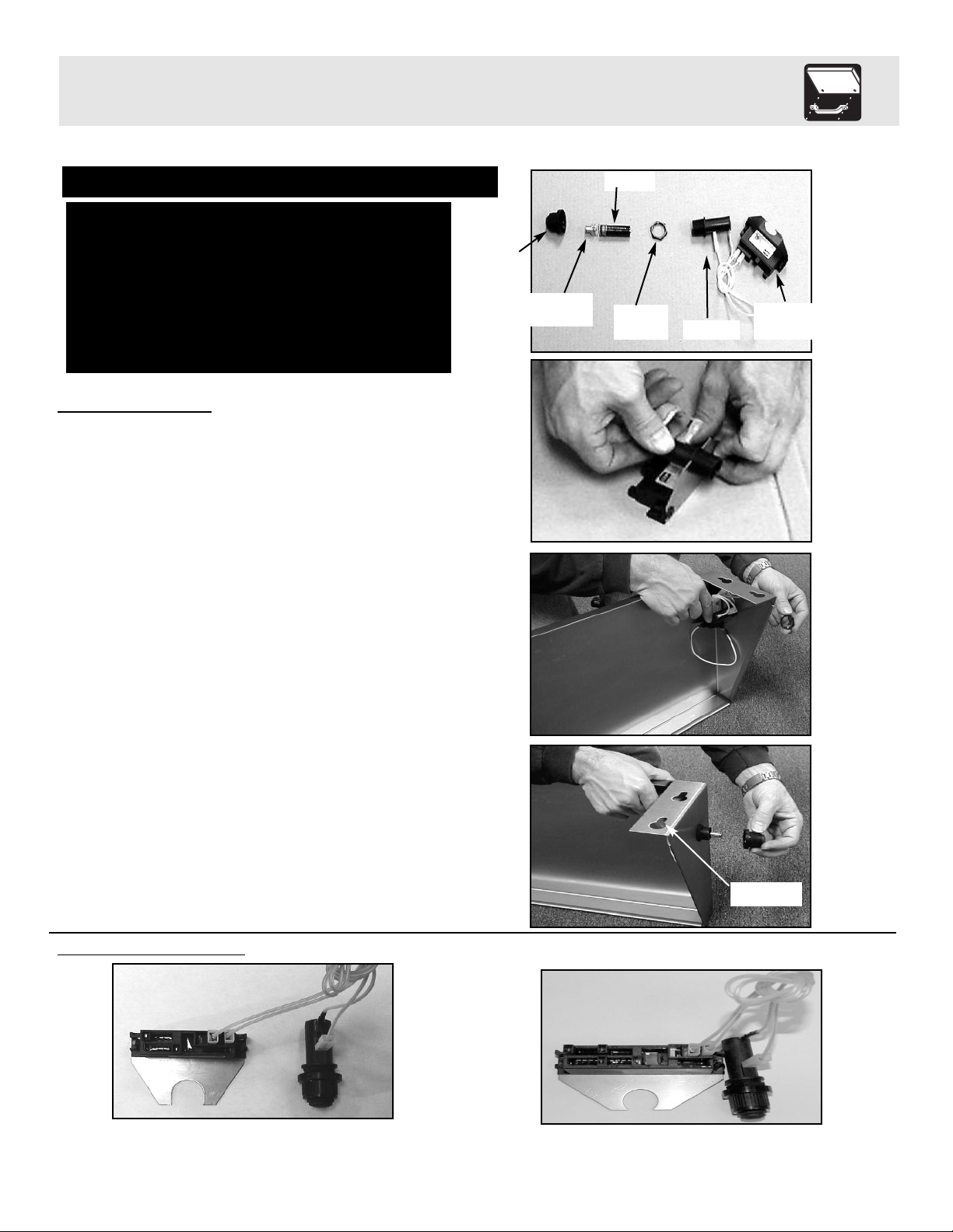
Ignitor Attachment
1. Remove the ignitor cap, spring assembly, battery and lock nut from ignitor. (See Fig. 1)
2. Insert the threaded section of the ignitor into
the U-shaped cut out of the ignitor mounting
bracket. (See Fig. 2)
3. Insert the threaded section of the ignitor
through the hole in the shelf and secure to
shelf using the lock nut. (Use the ignitor
assembly diagrams to determine which
ignitor goes with which shelf depending on
grill model.) Tighten Securely. (See Fig. 3)
4. Re-insert the battery, positive side first, and
spring assembly and attach the ignitor cap.
(See Fig. 4)
5. Repeat above steps for second ignitor
on the Side Burner.
GL44 Ignitor
Assembly
Fig. 1
Fig. 2
Fig. 3
Fig. 4
Note: Prior to assembly remove protective film from stainless steel parts
Assembly requires: 4 tools and a Friend
Tools required:
1/4” socket wrench
1/2” socket wrench
adjustable wrench
scissors
Grill Assembly
Side Burner (Three Wire)
Left Shelf (Double Wire)
Cap
Battery
Spring
Assembly
Locking
Nut
Cylinder
Mounting
Bracket
Keyhole
5
Side Shelf and Side Burner Attachment
1. Loosen the bolts on the side of the grill and
attach the shelf by allowing the bolt heads to
fall through the large opening in the bottom of
the keyhole slots. Then slide the shelves
downward until the bolts are resting against
the top of the key hole slots. Tighten all of
the shelf bolts. (See Fig. 5)
2. Attach the wires coming out from the sides of
the grill to the ignitor terminals. (See Fig. 6)
Note: It does not matter which wire goes to which
terminal on the double wire ignitor
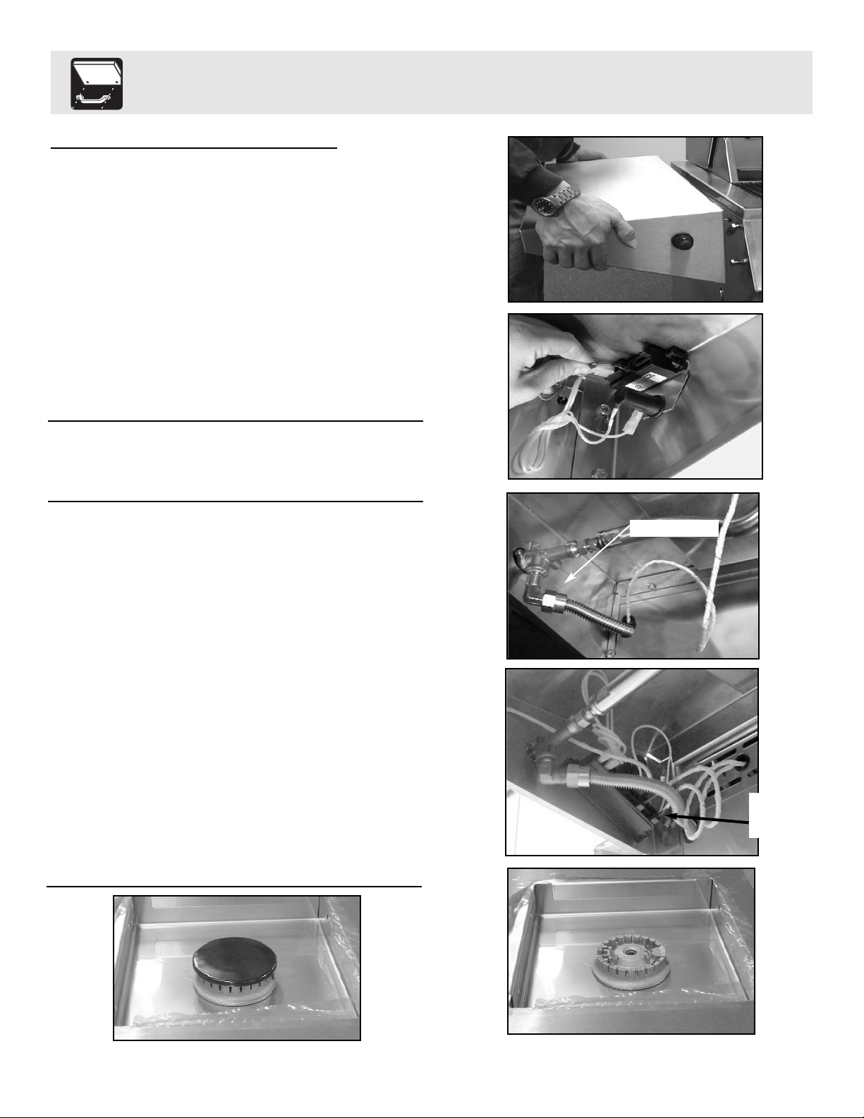
1. Attach the side burner by allowing the bolt
heads to fall through the large opening in the
bottom of the keyhole slots. Then slide the
side burner downward until the bolts are
resting against the top of the key hole slots.
Tighten all of the side burner bolts.
2. Screw the Flex Line coming from the side of
the grill to the fitting on the bottom of the
Side Burner. (See Fig. 7)
3. Attach the ignitor wires coming out from the
side of the grill to ignitor terminals.
(See Fig. 8)
Note: It does not matter which wire goes to which
terminal on the three wire ignitor
4. Install burner into side burner tray lining up
the three cutouts on the underside of the
burner. (See Fig. 9)
5. Install burner cap onto burner (See Fig. 10)
Side Shelf/Side Burner Assembly
Fig. 5
Fig. 6
Fig. 7
Fig. 8
Fig. 9
Fig. 10
Attach to fitting
Ignitor
wires
hookup
 Loading...