

Page 1

9600 D
Cooker hood
Operating and Installation Instructions
Page 2
Contents
Safety warnings 4
for the user 4
for the installer 4
Description of the Appliance 6
Extractor version 6
Filter Version 6
Control Panel 7
LED Indicator lights for verifying the saturation of filters 8
Led – Indicator for grease filter C 8
Led - indicator for charcoal filter D 8
Resetting the saturation indicator 8
Maintenance and care 9
Metal grease filter 9
Open the metal grease filter 9
Charcoal filter 1 0
Remove the upper glass panel 11
Changing the light bulb 1 1
Cleaning 12
Special accessories 12
T echnical assistance service 12
T echnical Specifications 1 3
Mounting accessories included 13
Electrical connection 1 4
Safety warnings for the electrician 14
Mounting 15
Printed on recycled paper
AEG - putting words into action
2
13
Page 3
Safety warnings
for the user
• Always cover lighted elements, to prevent excess heat from
damaging the appliance. In the case of oil, gas and coal fired
cookers it is essential to avoid open flames.
• Also, when frying, keep the deep frying pan on the cooker top/cooker
under careful control.
• The hot oil in the frying pan might ignite due to overheating.
• The risk of self-ignition increases when the oil being used is dirty .
• It is extremely important to note that overheating can cause a fire.
• Never carry out any flambé cooking under the hood.
• Always disconnect the unit from the power supply before
carrying out any work on the hood, including replacing the
light bulb (take the cartridge fuse out of the fuse holder or switch off
the automatic circuit breaker).
• It is very important to clean the hood and replace the filter at
the recommended intervals. Failure to do so could cause
grease deposits to build up, resulting in a fire hazard.
• The appliance is not intended for use by young children or infirm
persons without supervision.
• Y oung children should be supervised to ensure that they do not play
with the appliance.
• WARNING - Ensure that the appliance is switched of f before
replacing the lamp to avoid the possibility of electric shock.
for the installer
• When used as an extractor unit, the hood must be fitted with a
150mm diameter hose.
• Should there already be a pipe of diameter 125 mm that ducts to the
outside through the walls or roof, it is possible to use the 150/125
mm reduction flange provided. In this case the hood will be slightly
more noisy .
• When installing the hood, make sure you respect the following
minimum distance from the top edge of the cooking hob/ring
surfaces:
electric cookers 500 mm
gas cookers 650 mm
coal and oil cookers 700 mm min.
• The national Standard on fuel-burning systems specifies a maximum
depression of 0.04 bar in such rooms.
3
Page 4
• The air outlet must not be connected to chimney flues or combustion
gas ducts. The air outlet must under no circumstances be connected
to ventilation ducts for rooms in which fuel-burning appliances are
installed.
• It is advisable to apply for authorization from the relevant controlling
authority when connecting the outlet to an unused chimney flue or
combustion gas duct.
The air outlet installation must comply with the regulations laid down
by the relevant authorities.
• When the unit is used in its extractor version, a sufficiently large
ventilation hole must be provided, with dimensions that are
approximately the same as the outlet hole.
• National and regional building regulations impose a number of
restrictions on using hoods and fuel-burning appliances connected to
a chimney , such as coal or oil room-heaters and gas fires, in the
same room.
• Hoods can only be used safely with appliances connected to a
chimney if the room and/or flat (air/environment combination) is
ventilated from outside using a suitable ventilation hole approximately
500-600 cm2 large to avoid the possibility of a depression being
created during operation of the hood.
• If you have any doubts, contact the relevant controlling authority or
building inspector’s office.
• Since the rule for rooms with fuel burning appliances is “outlet hole of
the same size as the ventilation hole”, a hole of 500-600 cm2, which
is to say a larger hole, could reduce the performance of the extractor
hood.
• If the hood is used in its filtering function, it will operate simply and
safely in the above conditions without the need for any of the
aforementioned measures.
• When the hood is used in its extractor function, the following rules
must be followed to obtain optimal operation:
— short and straight outlet hose
— keep bends in outlet hose to a minimum
— never install the hoses with an acute angle, they must
always follow a gentle curve only
— keep the hose as large as possible (preferably the same diameter
as the outlet hole).
• Failure to observe these basic instructions will drastically reduce the
performance and increase the noise levels of the extractor hood.
4
Page 5
Description of the Appliance
Extractor version
• The hood is supplied as an
extractor unit and can also be
used with a filtering function by
fitting one charcoal filter
(special accessory).
• Y ou will need original AEG
charcoal filter for this function
(see Special Accessories).
• The air is discharged to the outside through a pipe, which must
be fitted to connection flange A.
Fig. 1.
• In order to obtain the best
performance the hose should have a diameter equal to the outlet
hole.
Should there already be a pipe of diameter 125 mm that ducts to the
outside through the walls or roof, it is possible to use the 150/125
mm reduction flange provided. In this case the hood will be slightly
noisier.
Fig. 1
Filter Version
A
• The air is filtered through a charcoal
filter and returned to the kitchen
through the top grill of the outlet
pipe.
• Y ou will need an original AEG KF8
charcoal filter for the filtering
function. (See Special
Accessories).
• Fix the deflector using 4 screws Ø
3,5x6.5 mm. Fig. 2.
• Optionally , the position of the
chimney elements can be changed.
When using the hood in the filter
version the chimney must be fixed
at the top, with the air outlet grill at
the side.
Fig. 2
5
Page 6

Control Panel
• Best result are obtained by using a low speed for normal conditions
and a high speed when odours are more concentrated.
Turn the hood on a few minutes before you start cooking, you will
then get an under pressure in the kitchen. The hood should be left on
after cooking for about 15 minutes or until all the odours have
disappeared.
The control switches are located on the unit’s front panel:
A - Main switch, hood on/off.
B - Start and choice of motor speed 1-2-3-1-2.........
C - Indicates speed 1 (LED) and indication of the grease
saturation for the filter (flashing indicator).
D - Indicates speed 2 (LED) and indication of the charcoal
saturation for the filter (flashing indicator).
E - Indicates speed 3 (LED)
F - Indicates Intensive speed (LED).
G - Intensive speed on/off. The Intensive speed runs for 5
minutes:
If the hood is on when the Intensive speed is activated, the
hood reverts to previous speed after 5 minutes.
If the hood is off when the Intensive speed is activated, the
hood will be turned off after 5 minutes.
T o interrupt the Intensive speed, press button A or B.
H - Light ON/OFF
Should the hood or the controls fail to operate: disconnect the power
supply for at least 5 seconds, then turn the hood back on again.
6
Page 7

LED Indicator lights for verifying the saturation
of filters
This hood is supplied without a charcoal filter. If the hood is to be used
in the recirculation mode with a charcoal filter, the saturation indicator
must be activated as follows:
Depress and hold the A and B buttons simultaneously for 3 seconds.
Initially only the LED indicator signal for the grease filter C is activated,
shortly after the LED indicator for the charcoal filter D will activate, at
this point the saturation detection has been enabled.
T o switch of f the saturation detection : depress and hold the A and B
buttons for 3 seconds until the LED indicator for the active carbon filter
is flashing.
Led – Indicator for grease filter C
The LED indicator for the grease filter will flash when it requires
cleaning.
Follow the maintenance instructions.
Led - indicator for charcoal filter D
The LED indicator for the charcoal filter illuminates when the filter
requires replacing.
This occurs after about 160 working hours from when the active carbon
filter was first put into operation.
Resetting the saturation indicator
After cleaning or replacing the filter depress and hold the G and H
buttons again for 3 seconds until the grease filter LED or the charcoal
indicator LED are no longer flashing.
7
Page 8

Maintenance and care
• The hood must always be disconnected from the electricity
supply before beginning any maintenance work.
Metal grease filter
• The purpose of the grease filters is to aspirate grease particles which
form during cooking and it must always be used, either in the
external evacuation or internal recycling function.
Attention: the metal grease filters must be removed and washed,
either by hand or in the dishwasher, every four weeks.
Open the metal grease filter
• First, push the metal grease filter stop backwards, then extract the
filter, pulling downwards. Fig. 3.
Hand washing
Soak grease filters for about one hour
in hot water with a grease-loosening
cleaner, then rinse off thoroughly with
hot water. Repeat the process if
necessary . Refit the grease filters
when they are dry .
Dishwasher
Place grease filters in dish washer.
Select most powerful washing
programme and highest temperature,
at least 65°C. Repeat the process.
Refit the grease filters when they are
dry.
When washing the metal grease filter
in the dishwasher a slight
discoloration of the filter can occur,
this does not have any impact on its performance.
• Clean the inner housing using a hot detergent solution only
(never use corrosive, abrasive or flammable cleaning
products).
8
Fig. 3
Page 9

Charcoal filter
• The charcoal filter should only be used if you want to use the hood in
its filtering function.
• To do this you will need an original AEG charcoal filter (see special
accessories).
• Cleaning/replacing the charcoal filter
Unlike other charcoal filters, the LONGLIFE charcoal filter can be
cleaned and reactivated. At normal use the filter should be cleaned
every second month. The best way to clean the filter is in the
dishwasher. Use normal detergent and choose the highest temperature (65º C). Wash the filter separately so that no food parts gets
stuck on the filter and later causes bad odours. T o reactivate the
charcoal, the filter should be dried in an oven for 10 minutes with a
temperature of maximum 100º C.
After approximately three years of use, the charcoal filter should be
replaced with a new, as the odour reduction capacity will be reduced.
• Mounting
Fit the charcoal filter first on the rear side, then use its red lock-keys
A to fix to the body of the hood. Fig. 4.
• T o dismount proceed in reverse order.
• Always specify the hood model code number and serial number
when ordering replacement filters. This information is shown on the
registration plate located on the inside of the unit.
• The charcoal filter can be ordered from the AEG technical
assistance service.
A
A
Fig. 4
9
Page 10

Remove the upper glass panel
The upper glass panel can be removed for cleaning.
• Remove the grease filters.
• Pull the handle L down. Fig. 5.
• Remove the glass panel.
L
Fig. 5
Warning
• Failure to observe the instructions on cleaning the unit and changing
the filters will cause a fire hazard. Y ou are therefore strongly
recommended to follow these instructions.
• The manufacturer declines all responsibility for any damage to the
motor or any fire damage linked to inappropriate maintenance or
failure to observe the above safety recommendations.
Changing the light bulb
• Disconnect the cooker hood from the main supply .
• Remove the lamp cover , use a screw driver as a lever. Fig. 6.
• Replace the old bulb with a new one of the same type.
• Remount the lamp cover.
• If the light does not come on, make sure the bulb has been inserted
in correctly before contacting the technical assistance service.
Fig. 6
10
Page 11

Cleaning
• Warning: always disconnect the hood from the mains power supply
before cleaning it.
Never insert pointed objects in the motor’s protective grid.
• Wash the outside surfaces using a delicate detergent solution. Never
use caustic detergents or abrasive brushes or powders.
• Only ever clean the switch panel and filter grille using a damp cloth
and delicate detergents.
• It is extremely important to clean the unit and change the filters at
the recommended intervals. Failure to do so will cause grease
deposits to build up that could constitute a fire hazard.
Special accessories
Charcoal filter KF8 E-Nr.: 942 1 18 648
T echnical assistance service
Y ou are welcome to telephone our technical assistance service (see list
of technical assistance centres) whenever you need information or in
the unlikely event of a fault.
When calling, please be ready to specify:
1. The model code number
2. The serial number (E-Nr.)
3. The manufacturing number (F-Nr.)
This information is shown on the registration plate inside the unit
behind the grease filter.
We reserve the right to change specifications and colours as a result of
our policy of continuing technological development.
11
Page 12

Technical Specifications
Models 9600 D
Dimensions -
Height 80-122,5
Width 89,8
Depth 52
Dimensions - filter version (in cm):
Height 82-122,5
Width 89,8
Depth 52
Maximum absorbed power: 215 W
Motor absorption: 1 x 130 W
Lighting: 4 x 20W
Length of the cable: 150 cm
Mounting accessories included
6 wood-screws 6 x 70 mm
4 nuts
6 wall plugs Ø 10 mm
2 metal screw 2,9x6,5
36 metal screws 4 x 8
1 reduction flange Ø 125-120 mm
1 deflector
extractor ver (in cm):
12
Page 13

Electrical connection
Safety warnings for the electrician
Before connecting the appliance to the power supply , check that the
voltage indicated on the rating plate corresponds to the mains power
supply available. Appliances fitted with a plug can be connected to any
standard power socket within easy access.
Should it be necessary to provide a fixed connection, the hood must
only be installed by an electrician authorised by the local electricity
board. T o isolate the cooker hood from the mains, pull the mains plug.
If the appliance is permanently connected to the mains, then it must be
isolated from the mains using measures provided in the electrical
installation (fuses -unscrew-type fuses, cut-out, current trips or similar
that have a contact separation of >3mm when open).
The manufacture declines all responsibility for malfunctions resulting
from failure to comply with the above instructions.
If the power socket is applied directly above the hood this gives two
advantages:
1. The socket is not visible.
2. The appliance can be disconnected at need merely be removing the
plug.
Electrical connection
220-240 V – by means of fixed power cable with plug.
(Fixed connection of the appliance must only be carried out by an
authorised electrician.)
13
Page 14

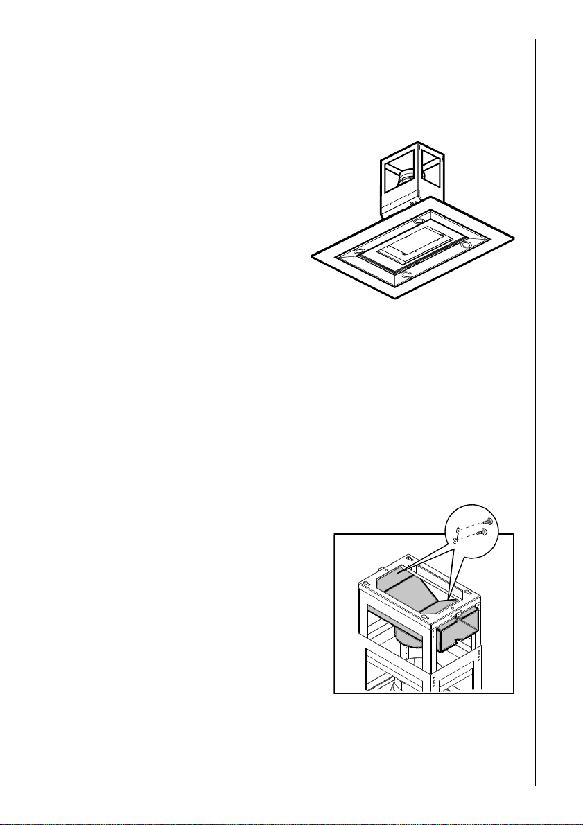
Mounting – Figure 7
• Place the outline (1) on the angle above the cooker hood.
• As demonstrated, drill the hole and insert four screw anchors and
four screws (2). Do not screw in the screws completely , because
they act as a hook for the cooker hood.
• Prepare the electrical connections and realize a perforation on the
wall where the cooker hood is required to be mounted in the external
air discharge version.
• Remove the telescopic structure A from the four screws (3), use a
pencil to mark two perforation for the safety screws, remove the
telescopic structure again A, drill both perforations and insert both
the screw anchors (4).
• Adjust the telescopic structure: the three components render
possible a lengthening between 80 and 100 cm (A). When both
upper components (B) are divided in the same way , the structure
may be lengthened between 100 and 120 cm (between 100 and
100.5 cm in the model with the tube).
Only for extractor version
• Fix the deviation plate F for the air circulation with four screws (2 x 2)
on the upper part of the structure A and secure it with a tubing of
suitable length (5) to the cooker hood’s discharge.
Only for the filter version
• Ensure that the tube is long enough at the connection ring above the
cooker hood (5).
After selecting the preferred installation, proceed in the
following manner:
• Suspend the box (ensuring that the electrical connection box is on
the side where the command components are to be located) and
screw in the four screws (6). Introduce and screw in both the safety
screws (7).
• Carry out the electrical connection (8).
• Introduce the chimney cap and fix it to the box with two screws (9),
and leave the lower part of the tab momentarily hanging downwards
(10).
• Suspend the cooker hood covering in the box and affix the provided
nut screws (11). Screw in the four screws (10).
• Connect the motor (13a) and the lights (13b), move the lower side of
the chimney cap and fix it to the cooker hood using two screws (14).
14
Page 15

Bild 7
15
Page 16

AEG Hausgeräte GmbH
Postfach 1036
D-90327 Nürnberg
http://www.aeg.hausgeraete.de
© Copyright by AEG
LI1VVB Ed. 05/02
 Loading...