

Page 1
INSTRUCTION- AND
INSTALLATION BOOK
GB
6561 G-m SI 949600556
1
Page 2
Congratulations from AEG
Dear Customer,
Congratulations with your new Hob.
It is important that you become familiar with the functions and features of
the Hob. You should therefore read these operating instructions as they will
help you get the most out of your new Hob.
Pay extra attention to sections marked . These are warning texts to help
you avoid accidents.
Keep the operating instructions. They will come in handy if there is
something you are not sure about, and should accompany the Hob if it is
transferred to a new owner.
The structure of the operating instructions enables you to use them as a
reference manual. The first part of the operating instructions contains a
general description of your new product. Then follows a short introduction
of the things to do before you use the Hob for the first time. The section
“How to use” describes how the Hob is used in everyday life. Use this
section until you are familiar with your new Hob. The section “Cleaning
and Maintenance” provides information on both daily and more thorough
cleaning of the individual components of the Hob. Should problems arise
when you use the Hob, you can look in the section “Before calling service”,
where there are instructions on how to remedy some practical and technical
problems yourself.
Enjoy!
Regards,
2
Page 3
Table of contents
Contents Page no
For the user
Your new appliance ...................................................................................... 2
Safety information ........................................................................................ 4
Description of the product ......................................................................... 6
How to use .................................................................................................... 7
Inner- and outer burner ring ................................................................. 8
Burner cover......................................................................................... 8
Ignition electrode (A) ........................................................................... 8
Thermo Sensor (B) ............................................................................... 8
Ignition .................................................................................................. 9
Maintenance and cleaning of ................................................................... 10
Panel .................................................................................................. 10
Stainless steel surfaces ....................................................................... 11
The ceramic glass plate ...................................................................... 11
The gas burner.................................................................................... 12
Service .................................................................................................. 20
For the installer
Mounting .................................................................................................. 13
Technical data ............................................................................................. 19
How to read the operating instructions:
1... 2...Step by step
Safety information
3
Hint and tips
Environmental information
Page 4
Safety information
These warnings are provided in the
interests of your safety. Ensure you
fully understand them before installing
or using the appliance. Your safety is of
paramount importance. If you are
unsure about the meaning of these
warnings contact the Customer Care
Department for assistance.
Installing
Do not install the hob if the ceramic
glass is damaged or cracked.
This gas hob must be installed
according to the instructions supplied.
Any installation work must be
undertaken by a qualified competent
person.
Do not alter the specifications or
attempt to modify the appliance in any
way.
During Use
The gas hob is intended for domestic
cooking only. It is not designed for
commercial/industrial purposes.
Ensure that all the control knobs are in
the OFF position when not in use.
Do not use the gas hob if it is damaged
in any way, contact your local AEG
Service Centre.
Never use plastic or aluminium dishes
on the gas hob.
Never leave the gas hob unattended
while deep fat frying, or heating fats
and oils.
Child Safety
Young children must not be allowed to
tamper with the gas hob or play with
the controls.
The gas hob gets hot when it is in use.
Children should be kept away until the
gas hob has cooled.
Maintenance and Cleaning
Only clean this gas hob in accordance
with the instructions given in this
book.
Service
Repairs carried out by inexperienced
persons may cause injury or serious
malfunction of the appliance. Repairs
must only be carried out by a
qualified/competent person. Contact
your local AEG Service Centre.
Disposal
Make the gas hob unusable by cutting
off the cable
Dispose of any packaging material and
old appliances at an authorised
disposal sites.
4
Page 5

The primary air intake
aperture
Must never be accidentally blocked
by objects of any kind.
5
Page 6
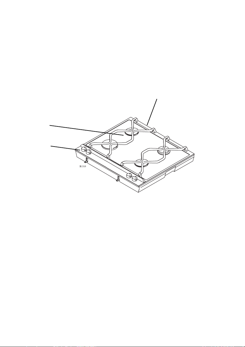
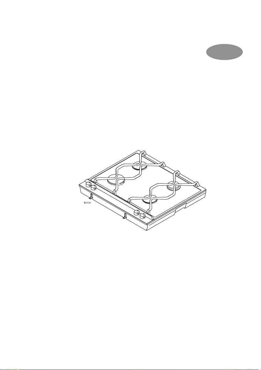
Description of the product
Air intake
Gas burner
Control knob
6
Page 7
How to use
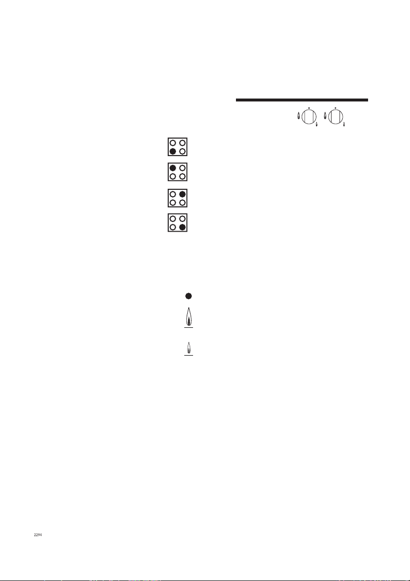
Burner markings
Symbols at each operating knob
indicate which burner is adjusted with
the control knobs.
Left front burner
Left back burner
Right back burner
Right front burner
Panel markings
Each operating knob has a ring
showing the scale of markings.
Off.
Maximum flame
Minimum flame
7
Page 8
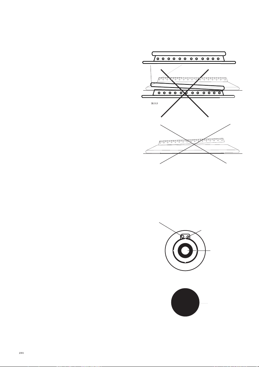
Burner cover/inner burner
ring/outer burner ring
Together with the inner burner ring the
outer burner ring forms a space where
the final mixture of gas and air takes
place in order for the gas burn correctly.
Please note: It is very important that the
inner burner ring/outer burner ring is
placed correctly, together with the cover.
See installation of the wok burner.
If the burner cover/rings are incorrectly
fitted the burner will not operate
correctly, and the burner may be
damaged within a short space of time. It
is also important, that the inner air ring
is placed correctly.
Ignition electrode (A)
The burner has been provided with an
ignition electrode. As long as the
operating knob is depressed, the
automatic ignition will ensure that a
spark is emitted between the ignition
electrode and the burner cover.
Thermo couple (B)
The gas unit features fully-secured gas
taps (thermo-couple)
In case the flame goes out, the thermo
couple automatically prevents gas
admission after a few seconds (Max. 90
seconds).
Note: Gas will flow while the operation
button is pressed - See start-up
procedure.
Cover
Ignition electrode (A)
Thermo couple (B)
Burner ring
Inner
burner
Outer
burner
8
Page 9

Ignition
1. Depress and turn the control knob
for the burner to the left to max.
flame . (Ignition position)
2. The ignition electrode will emit
sparks, and when the mixture of gas
and air is correct, the burner will be
ignited. If it is not possible to
connect the unit to mains, a
match may be used to ignite the
burner.
3. After starting the burner, press the
control knob for approx. 10
seconds to activate the automatic
thermo-couple (thermo sensor
ready).
5. The burner can now be regulated
between maximum and minimum
9
Page 10

Maintenance and cleaning
For reasons of hygiene and
safety, the cooking zones
must be kept clean. Grease
stains and spilled food
generate smoke when heated,
and can even cause fire.
The splashguard can be removed to
make it easier to clean the surface.
What to do:
1. Hold the splashguard as shown
in the diagram.
2. Lift the splashguard straight up
3. Clean the top surface as
described in “cleaning the steel
surface”.
Be aware of the two retaining
pegs, which are sharp.
4. Replace the splashguard in
position ENSURE that it is
fitted the correct way round.
Never use hard or sharp
implements to lift off the
splashguard.
Do not wash the splashguard
in a dishwasher.
The hob must not be used
with the splashguard off.
10
Page 11

Stainless steel surfaces
Perform daily cleaning with a slightly
damp cloth. For more severe soiling,
use a liquid cream. Always clean the
steel in the direction of the steel finish.
To ensure that the steel retains its
shine, it is recommended that you use
a polishing agent for stainless steel on
a regular basis. Always polish in the
direction of the steel finish (crosswise).
Never use steel wool, metal sponges or
other abrasive cleaning agents.
The ceramic glass
Immediately scrape off stains caused
by food which has boiled over, spilled
sugar, dishes containing sugar (jam,
juice, etc.), melted plastic and
aluminium foil while the ceramic glass
is still hot. If the ceramic glass is
allowed to cool it may become
damaged.
After use the ceramic glass should be
wiped with a damp cloth with washing
up liquid. For severe soiling you can
follow these steps:
1. Remove stains etc., with the
ceramic glass scraper.
2. Make sure that the hob has cooled
down. Use a ceramic
cleaning agent such as vitroclen.
Shake the bottle and apply a couple
of squirts to the ceramic hob.
3. Wipe the ceramic hob clean with
a damp cloth or kitchen towel.
Tough stains can be removed by
rubbing the stain hard with
kitchen towel.
4. Wipe off remaining cleaning
agent with a damp cloth.
5. Wipe with a dry cloth, if
required.
Make sure that the ceramic glass is dry
when you heat it up again. Ceramic
glass can develop rainbow-like stripes
if heated while damp.
Spillages must be removed
immediately, while the burner is still
warm, using a ceramic glass scraper.
Especially damaging are melted
plastic, aluminium, or any foodstuff
containing sugar, including natural
sugar, as these can create permanent
“pockmarks” and craters on the
ceramic surface. After cleaning, polish
thoroughly with the cleaning agent
supplied with the unit.
Defects in the ceramic surface which
can be related to the above are not
covered by the warranty.
Warning:
Aluminium foil and plastic utensils
should not to be placed on hot
surfaces.
The surface should not be used for
storage.
11
Page 12

Cleaning of gas burners
Clean the control panel and knobs plus
the pan grid, as well as burner caps and
rings, with ordinary cleansing agents.
Never use scouring powder, Brillo
pads, metal pads or other scouring
agents on enamelled or painted
surfaces!
Avoid boil-over
If water accidentally gets into the edge
of the burner head (boil-over) the
water must be removed with a lint-free
cloth before the burner is turned on
again.
Likewise, caps and grids must be
thoroughly wiped off before the gas
ring is used again so that the boil-over
does not permanently scar the enamel
or paint.
12
Page 13

Mounting
Caution: In order to avoid a hazard this
appliance must be installed according to
these instructions for installation
The hob unit can be mounted in any
type of kitchen with a table surface
whose thickness is between 28 mm and
40 mm.
Fixing
Screw the fixing brackets out to such an
extent that they can be turned in under
the table top. Tighten the brackets on to
the table top with an ordinary
screwdriver.
Cut-out measurements
One rectangular hole is sawn out for the
hob combination chosen.
The depth of the cut-out for any unit is:
490 mm
Length of hole = sum of all units`
externally measured length, less 20 mm.
Minimum distance
to wall:
150 mm
Minimum distance
to wall (nonflammable material):
50 mm
Mounting of Reinforcement
Beams
A reinforcement Beam, with supporting
flanges at each end, is included with
each two-burner unit. For unit
combinations, a reinforcement beam
must be used between each unit.
Reinforcement
beams
13
Page 14

It is not necessary to attach the
reinforcement beam to the table
surface, as it is held in place by a
specially designed moulding, which is
incorporated in the hob units flanges.
Installation in work tops with a
base unit underneath
If the hob is to be installed on top of a
base unit, a board must be mounted
underneath the hob (e.g. 16 mm chip
board).
Seal all joints with aluminium tape.
The board can be mounted as shown in
the diagram.
This installation method prevents the
flames from being extinguished if you
close the door of the base unit hard.
Min. 140 mm
Min. 16 mm
Aluminium-tape
If the back panel of the cupboard unit
is of thin 4 mm material, it will need to
be reinforced.
This procedure will prevent the gas
being blown out if the cupboard door
is slammed shut.
Min. 140 mm
Min. 16 mm
Aluminium-tape
14
Page 15

Do not install the hob above drawers.
15
Page 16

Do not install the hob above
drawers.
Combined installation with
oven
If the oven is placed directly under
the dropinette a metal plate must be
installed in between. The metal
plate is included in the installation
kit intended for this combination.
The kit, product number 949 600
970, can be ordered from your
kitchen appliance dealer.
This gas hob can be combined
with AEG Competence ovens
with a maximum power of
3,8 kW.
16
Page 17

The unit´s externally
measured length
145 mm:
Cooker hood
290 mm:
Two-zone ceramic-top electric hob
Two-burner gas hob
Grill
Fryer
Wok
580 mm:
Four-zone ceramic-top electric hob
Four-burner gas hob
725 mm:
Four-zone ceramic-top electric hob
Installation of a single unit
When mounting a single unit, be it a
half-or full size unit, in a table surface
which is thicker than 30 mm, it is
necessary to make a special notch in
both sides of the cut-out hole, as
shown in the adjacent drawing.
The purpose of these notches is to
create space for the electrical cables.
17
Page 18

Gas installation
In accordance with local
requirements for domestic gas
cooking appliances.
Gas installation must only be
carried out by an authorised person.
For gas types see technical data.
Gas connection
The gas intake is situated at the
lower rear of the appliance. The
intake has a ½" conical pipe thread
(see fig 1) If the appliance is to be
connected to a gas cylinder,
conversion with the optional
modification kit will be necessary.
Pressure test
The unit should be pressure-tested
at Max. 150 mbar.
18
Page 19

Technical data
Type of gas
Adjusted to natural gas: G20 - 20 mbar
Category and pressures
II
2H3B/P
Convertible to
Bottled gas - G30 - 30 mbar
Max. nominal load Q na HS:
Small sized burner= 1,0 kW x 1
Medium sized burner = 1,9 kW x 2
Large sized burner = 2,7 kW x 1
Total= 7,6 kW
FSD
The unit features fully-secured gas
taps (thermo-fuse).
HS = Top calorific value
Q = Nominal load
Cable type: 0,75 mm² HO5 V2V2-F
240 V
1N + PE
N L1
The Dropinett must be connected via
an external switch with a contact
gap of min. 3 mm (the main switch
may be used)
Wiring
HO5V2V2-F
Blue and brown: 51 mm +/- 3 mm
Yellow/Green: 61 mm +/- 3 mm
ID. CE-048AU-0003
Ignition transformer= 50 HZ - 0,6 VA
Radio-noise reduction
This unit observes the current EECdirective on radio noise reduction.
This gas appliance is -approved and
marked in accordance with the gas
appliance Directive (90/396/CEE), the
low voltage directive (73/23/CEE) and
the EMC directive (89/336/CEE incl.
the agreed directive changes.
19
Page 20

Service
If the hob is not working correctly, please carry out the following checks before
contacting your local AEG Service Centre.
IMPORTANT: If you call out an engineer to a fault caused by incorrect use or
installation, a charge will be made even if the hob is under guarantee.
Sympton:
There is no spark when lighting the
gas
When the operating knob is released
the gas ring goes out again
The gas ring burns unevenly
If after all these checks, your hob still does not operate correctly, contact your
local AEG Service Centre.
In-guarantee customers should ensure that the above checks have been made as
the engineer will make a charge if the fault is not a mechanical or electrical
breakdown.
Solution
Check hob is connected to the
electricity supply. Check the fuse and
replace if necessery.
The operating knob has not been
depressed long enough, or has not
been depressed sufficiently.
Ensure the cover has been replaced
correctly, e.g. after cleaning.
Please note that it will be necessary to provide proof of purchase for any inguarantee service calls.
20
Page 21

212223
Page 22

Page 23

Page 24

24
325 88-3719 Rev. 4-252
 Loading...