

Page 1

GENERAL INDEX
GB
D
NL
F
SP
................................................ Pag. 1÷9
................................................ Pag. 10÷18
I
................................................ Pag. 19÷27
................................................ Pag. 28÷36
................................................ Pag. 37÷45
................................................ Pag. 46÷54
FORLI' Italy
INDEX
Description Page
1.0 Identification .................................................. 2
1.1 Manufacturer ..................................................... 2
1.2 Definitions .......................................................... 2
1.3 Transport - Handling - storage ........................... 2
1.3.1 Storage conditions ............................................. 2
1.3.2 Weight ............................................................... 2
1.3.3 Overall dimensions ............................................. 2
1.3.4 Handling ............................................................ 2
2.0 Installation...................................................... 2
2.1 Authorised personnel ......................................... 2
2.2 Mounting the generator...................................... 3
2.3 Electrical connections ........................................ 3
2.3.1 Connection of the battery recharger ................... 3
2.3.2 Connection of the starter battery ........................ 3
2.3.3 Connection of the remote control panel ............. 3
2.4 Installing the fuel tank ......................................... 3
Connection to gas canister ................................ 3
3.0 General operation ......................................... 4
3.1 Description of generator and functioning ............ 4
3.2 Safety advice ..................................................... 4
3.3 Noise levels........................................................ 4
4.0 Instructions for use ...................................... 5
4.1 Starting the generator ........................................ 5
4.2 Stopping the generator ...................................... 5
4.3 Inherent risks ..................................................... 5
4.4 Improper use ..................................................... 5
4.5 Useful advices.................................................... 5
4.6 Troubleshooting ................................................. 5
5.0 Maintenance operations .............................. 6
5.1 Nature and frequency of checks ........................ 6
5.2 Maintenance operations which do not
require qualified technicians ............................... 6
5.3 Maintenance operations which require
qualified technicians ........................................... 6
5.3.1 Oil change ......................................................... 7
5.3.2 Air filter maintenance.......................................... 7
5.3.3 Spark plug maintenance .................................... 7
5.3.4 Regulating the voltage........................................ 8
6.0 Inactivity and dismantling ........................... 8
6.1 Dismantling ........................................................ 8
7.0 Dealing with fire hazards............................. 8
8.0 Technical data sheet .................................... 9
8.1 Technical specifications ..................................... 9
8.2 Wiring diagrams .........................................55÷71
© WTA srl -1998
All rights reserved
Printed in Italy
Text and graphics by: VEGA - Forlì
No part of this publication may be reproduced, copied or transmitted in any form or by any means without prior written permission from WTA
srl.
Figures, descriptions, reference and technical data in this manual are given as mere example and are not binding.
Because of WTA policy of continual product and safety improvement, we reserve the right to make changes at any time without notice.
1
Page 2
FORLI' Italy
1.0 IDENTIFICATION
The identification plate of the machine is affixed outside
the plate casing (see fig. 1).
1.1 MANUFACTURER
WTA srl
Via Virgilio, 3
47100 FORLI' - ITALY
P. IVA 00718330400
1.2 DEFINITIONS
In this handbook, three types of “safety graphics” are used
to point out different levels of danger or any other important
information:
DANGER
Draws attention to potentially dangerous situations which
may cause serious personal injury.
CAUTION
Draws attention to potentially dangerous situations which
may cause personal injury or material damage.
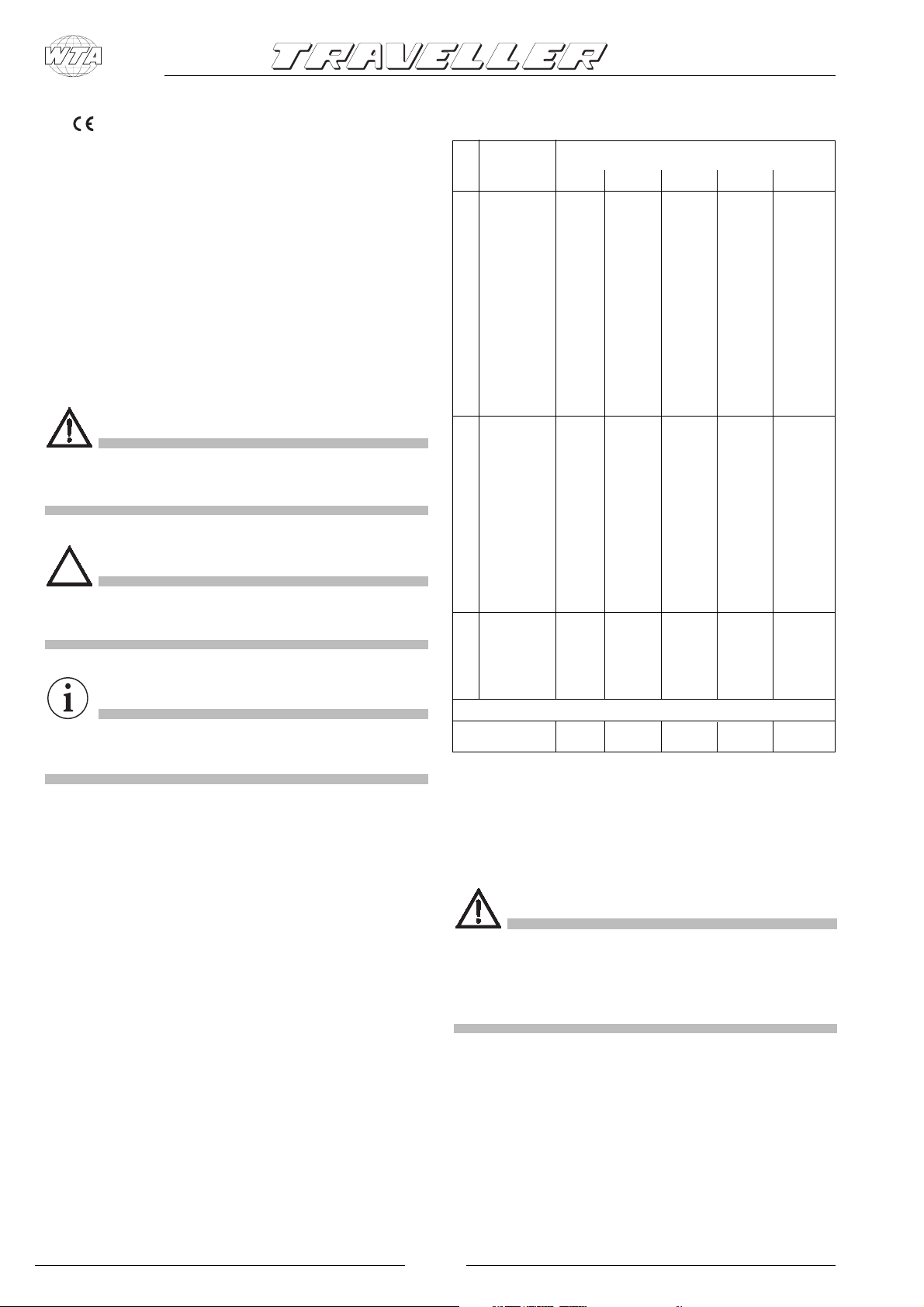
1.3.3 OVERALL DIMENSIONS
See figg. 2, 3, 4 :
Model
1000 2500 3000 4000 5500
A mm 470 530 570 660 700
B mm 535 605 650 740 -C mm 565 640 680 770 -D mm 320 385 385 475 515
E mm 315 290 290 355 510
F mm 260 295 295 310 -Gmm27303062 -H mm -- 360 360 -- --
I mm 65 87 113 78 -Lmm659697265 -M mm 225 222 230 130 -Nmm36282517 -O mm 535 605 650 740 735
Pmm2730306255
TYPE "B" INSTALLATION TYPE "A" INSTALLATION
Q mm 260 295 295 310 370
X mm 590 650 690 780 770
IMPORTANT
Draws attention to situations which may cause
malfunctioning or damage to the machine.
1.3 TRANSPORT - HANDLING - STORAGE
1.3.1 STORAGE CONDITIONS
The generator is protected against sudden impact by
suitable packing consisting of cardboard, polystyrene and
a wooden frame support.
The generator should be stored horizontally in a dry and
well-ventilated room.
1.3.2 WEIGHT
Gross weight (including packing):
Mod. 1000 .......................................... Kg 50
Mod. 2500 .......................................... Kg 62
Mod. 3000 .......................................... Kg 71
Mod. 4000 .......................................... Kg 114
Mod. 5500 .......................................... Kg 140
Y mm 385 430 435 540 505
Z mm 335 305 305 380 550
OPENING DIM.
Air intake area
2
cm
220 220 220 260
1.3.4 HANDLING
The packed generator can be handled by normal means of
lifting and transport.
Boxes are fitted with spacers which enable the use of
manual fork-lifts.
DANGER
Strictly observe the accident prevention precautions and
safety regulations during lifting and transport, and always
use machines
be lifted.
2.0 INSTALLATION
2.1 AUTHORISED PERSONNEL
The generator shall be installed onto the vehicle (caravan,
motorhome or special vehicle) by authorised personnel
only, namely by skilled technicians or workshops, authorised
directly by W.T.A.
If the installation is carried out by non-authorized technicians
with a higher maximum capacity than the load to
2
Page 3
or workshops, W.T.A. disclaims any responsibility for the
safety and efficient running of the generator according to
the M.D. 89/392/EEC.
DANGER
The instructions given in sections 2.2 - 2.3 - 2.4 are
addressed to qualified technicians only.
2.2 MOUNTING THE GENERATOR
Generators mod. 1000 - 2500 - 3000 - 4000 are provided
with fixing brackets,vibration dampers and petrol filter to be
placed on the fuel feed hose to the generator. Brackets
allow either suspended type "A” mounting (see fig. 3) or
traditional type "B” mounting (see fig. 4).
This is made possible by the supporting frame of the outer
casing.
Generator mod. 5500 is provided with brackets for fixing
the external seal, brackets for anchoring the unit, vibration
dampers, silencer (pos. 29 fig. 16) to be coupled to the
exhaust hose delivered as accessory AG 125 (pos. 34 fig.
16), and fuel filter which is standard installed inside the
casing (pos. 33 fig. 15). The brackets (pos. 31 fig. 16) which
allow to fix the seal (pos. 35 fig. 16) allow to mount the
generator complete with seal inside the arranged
compartment and to perfectly seal the vehicle side. The
exhaust hose can be positioned at will as shown in fig. 16
by rotating the curve inwards to either upper position or
lower position. By removing the curve, it is also possible to
directly fit the exhaust pipe by crossing the casing on its lefthand side. The prearranged floor must tolerate both the
generator mass and the vibrations due to the motion of the
vehicle ("TYPE B” mounting).
The type “A” mounting (suspended installation) offers the
following advantages: reduced overall dimensions, quick
installation, easy access for both ordinary and extraordinary
maintenance operations.
Make sure there is enough space around the generator
casing for air to pass freely (for cooling). It is also necessary
to leave at least 20 mm distance between the casing and the
surrounding parts.
If the breathing manifold is positioned behind one of the
vehicle's wheels, make sure that the tyre is prevented from
throwing water into the casing when travelling on wet roads.
For the type “A” mounting, use the plate supports provided
to ensure that the genset is fixed securely. If type “B”
mounting is preferred (traditional installation), a watertight
compartment (fig. 2), set towards the vehicle interior and
having the dimensions given in section 1.3.3, needs to be
prearranged, with exhaust holes and air inlets drilled into the
floor and door. In addition, use an exhaust union (fig. 4),
supplied as accessory, to be fixed directly onto the generator
casing with screws or rivets. In order to prevent the exhaust
gas recycling within the compartment, place flameproof
sealing around the exhaust union.
FORLI' Italy
2.3 ELECTRICAL CONNECTIONS
For the 230V use a standard cable with cross-section
according to table 1 below. Pass it inside the casing via the
airlead (pos. 30 fig. 7 and 9) and connect to the terminals
(pos. 17/18 fig. 6 and 14). Connect the earth wire to pos. 15.
The electrical circuit should have a relay or change-over
switch (such as accessory AG102/AG113), so as to prevent
any damage to the generator when the camper is connected
to an external mains supply (precedence is automatically
given to the mains).
Mod.
Cross-section Cross-section
mm2 -230 V mm2-12 V
1000 1.5 6 10 16
2500 2.5 2.5 10 16
3000 2.5 2.5 10 16
4000 4 2.5 10 16
5500 4 2.5 16 25
Power cables
Battery recharger
6 m > 6 m
Battery connection
TAB. 1
2.3.1 CONNECTION OF BATTERY
RECHARGER
Use a wire with minimum cross-section according to table
1 above to connect the terminal (pos. 16 fig. 6 and 14) to
the positive lead of the battery to be recharged.
Insert the AG111 voltage regulator, or alternatively a switch,
to interrupt recharging when complete.
(See wiring diagrams, pages 55 ÷ 71).
2.3.2 CONNECTION OF STARTER BATTERY
For starting the generator, connect the positive terminal of
the vehicle's starter battery to pos. 12 fig. 6 and 14 using a
flame-resistant sheathed cable having a cross-section
according to table 1 above.
The earth cable should have the same cross-section and be
connected from pos. 13 to the vehicle chassis. Make sure
that a clean, rust-free contact is made (i.e. rub down surface
if painted), and protect with grease.
2.3.3 CONNECTION OF REMOTE CONTROL
PANEL
Fix the control panel in desired position inside the vehicle
and use the individually-tested AG103 extension cable to
connect it to the genset by means of the connector pos. 14
fig. 6 and 14.
2.4 INSTALLING THE FUEL TANK
Install the fuel tank as near as possible to the generator and
if possible on the same horizontal level, or up to 30cm
below. As well as reducing the length of fuel pipe as much
as possible, make sure it is not bent or squashed. Do not
put the tank near sources of heat, and make sure that water
3
Page 4

FORLI' Italy
cannot infiltrate.
Use LOCTITE 577 to make all connections, so as to prevent
fuel leakages.
To connect the fuel tank to the generator, use a 6x13mm
rubber-coated tube, of the same type used for the genset
and suitable for unleaded petrol. For the extension, use the
ties and filter provided. It is advisable to use fuel hose
AG118 (accessory) for the connection from tank to refuellingmouth.
IMPORTANT
Model 5500 does not need fuel tank, since it is standard
fitted inside the genset casing.
CONNECTION TO GAS CANISTER
DANGER
• The unit shall be used only and exclusively with the door
closed.
• Keep inflammable substances like petrol, paints, solvents,
etc. away from the generator.
• Do not let hot parts of the genset come into contact with
inflammable materials.
• Do not fill up with the engine running if the tank is placed
close to the generator.
• Do not touch the generator or its connections with wet
hands.
• Do not replace the fuses or thermal switches with new
ones of higher amperage.
• Any check of the electrical parts shall be made with
engine stopped and by authorised technicians only.
CAUTION
For the LPG genset, withdraw the gas from the upright
canister before the vehicle's service regulator and from the
upper part, so that gas enters the genset at high pressure
and in the gaseous state.
(Minimum recommended pressure: 0.7- 0.9 bar)
3.0 GENERAL OPERATION
IMPORTANT
The firm disclaims any responsability for damages arising
from malfunctioning of the generator.
3.1 DESCRIPTION OF GENERATOR AND
FUNCTIONING
The generator consists of an endothermic petrol engine
connected to an alternator which produces both alternate
and direct current.
The unit comes in a soundproof casing made of pressed
steel plate and insulated with special deadening materials.
Fuel comes to the combustion engine through a pump
which is standard fitted on the unit itself.
The generator is manufactured according to the safety rules
given in the Conformity Declaration.
3.3 NOISE LEVELS
The generator has been submitted to a noise emission test
at a qualified ISTEDIL lab, where all the necessary tests were
carried out and EC Certificate No.I-225/92 issued, stating
following results:
Measured according to: EC DIRECTIVE 84/536
NOISE LEVEL:
Mod. 1000 .......................................... LwA 81
Mod. 2500 .......................................... LwA 85
Mod. 3000 .......................................... LwA 85
Mod. 4000 .......................................... LwA 87
Mod. 5500 .......................................... LwA 87
3.2 SAFETY ADVICE
The unit is housed within a perfectly closed casing. Therefore,
there is no danger of accidental contacts with hot or moving
parts or wires under voltage.
The door of the unit is fitted with lock and key and should
not be left within the reach of children or non-authorised
persons.
4
Page 5

FORLI' Italy
4.0 INSTRUCTIONS FOR USE
4.1 STARTING THE GENERATOR
Normally the vehicle's 12V battery is used to start the
genset.
First press the red button (pos. 27 fig. 5) on the control panel
into the “I” position.
To start the genset from cold, press and hold down the
green START button (pos. 25 fig. 5) together with the white
CHOKE button (pos. 26 fig. 5) for max. 5 seconds.
When starting the LPG generator from cold, press the
green button (pos. 25 fig. 5) and at the same time "blip" the
white button (pos. 26 fig. 5) for about a second at intervals
of around 3 seconds. As soon as the engine fires, release
both buttons.
If the engine does not start, wait a few seconds, then repeat
the operation.
CAUTION
Do not make prolonged or repeated (more than 5 consecutive) attempts to start the genset, as this may damage the
starter motor.
4.4 IMPROPER USE
DANGER
The generator is to be installed by qualified technicians only,
according to the manufacturer’s instructions.
The generator is to be used only and exclusively for producing
current for mobile vehicles, fitted with a standard electrical
circuit in keeping with the power supplied by the generator.
4.5 USEFUL ADVICES
To use the genset at best, we remember you that little, but
prolonged, overloads may cut off thermal switches pos. 10
and 11 shown in fig. 6 and 14.
During running-in, it is advisable that the new engine is not
subjected to loads exceeding its nominal load by 70%, at
least during the first 50 running hours.
4.6 TROUBLESHOOTING
We have listed below some problems which may occur,
along with their respective causes and possible solutions.
In the case of problems which are not listed below, please
seek advice from an authorised after-sales service centre.
To start the genset when already warmed-up, or during the
summer, when the outside temperature is high, press the
green “START” button (pos. 25 fig. 5) only.
In an emergency the genset can be started manually using
the pull-cord handle (pos. 4 fig. 8 and 15) and holding the
choke magnet (pos. 36 fig. 8 and 15) shut with one hand
if the engine is cold.
The green LED on the control panel ((pos. 23 fig. 5) indicates
that the genset is running correctly.
4.2 STOPPING THE GENERATOR
Push the red “STOP” button (pos. 27 fig. 5) on control panel
into the ”0" position. Alternatively use the safety switch on
the genset itself (pos. 7 fig. 6 and 14) for models 2500 - 3000
- 4000 - 5500.
4.3 INHERENT RISKS
DANGER
The generator is fitted with a combustion engine, and
therefore runs on highly inflammable fuelstuffs.
Exhaust gases are conveyed under the casing and, although
mixed with cooling air, they are inevitably hot.
Do not touch the parts of the casing close to the exhaust
and do not place your hands or other objects within the
duct.
1 When the green “START” button (pos. 25 fig. 5)
on the control board is pressed, the generator
does not work.
Causes and Solutions:
1.1 Check that the red switch (pos. 27 fig. 5) is in the “I”
position.
1.2 Electrical wires loose or disconnected.
(Have checked by qualified personnel).
1.3 No power supplied to starter-motor.
(Have checked by qualified personnel).
1.4 Earth wire of generator disconnected.
(Have checked by qualified personnel).
2 The starter-motor turns, but the generator does
not start.
Causes and Solutions:
2.1 No fuel: check.
2.2 No oil in engine.
Check if the red warning light (pos. 6 fig. 5) on the
control board blinks during the starting phase.
Check the oil level and top up if necessary (see
Maintenance section).
2.3 The safety switch (pos. 7 fig. 6 and 14) is in the "0"
position.
Check and press in the “I” position.
2.4 Check that the engine's spark-plug nipple is fully
inserted.
2.5 No current to the spark plug.
(Have checked by qualified personnel).
2.6 No fuel getting to the carburettor.
(Have checked by qualified personnel).
5
Page 6

FORLI' Italy
3 The generator tends to stall.
Causes and Solutions:
3.1 No more fuel left in the tank: refill.
3.2 Low oil level.
Check and top up.
(See Maintenance section).
3.3 Air filter is dirty.
(Have checked by qualified personnel).
4 The generator does not produce current
Causes and Solutions:
4.1 Thermal switch off.
Set it to 'on' by pushing the switches (pos. 10 fig. 6
and 14) for 230V A.C., (pos. 11 fig. 6 and 14) for 12V
D.C.
4.2 Condenser (pos. 19 fig. 8) damaged.
(Have checked by qualified personnel).
4.3 Diode rectifier (pos. 21 fig. 8) damaged.
In this case, only the 12V D.C. and the green LED on
the control board are not working.
(Have checked by qualified personnel).
4.4 Rotor diodes damaged.
(Have checked by qualified personnel).
4.5 Frequency too low.
(Have checked by qualified personnel).
5 The unloaded current produced oscillates.
Causes and Solutions:
5.1 Too much oil in the engine: check.
5.2 Defective carburation.
Have the carburettor cleaned by qualified personnel.
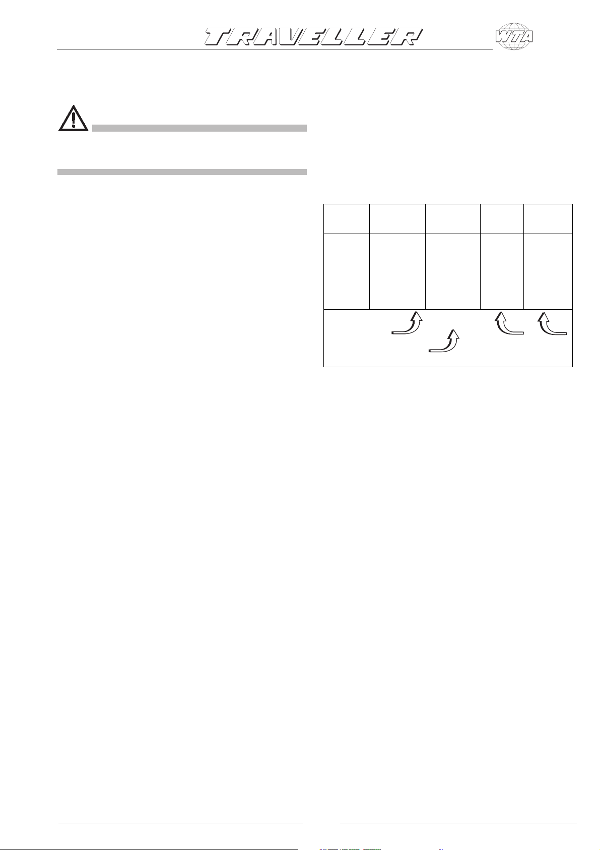
5.1 NATURE AND FREQUENCY OF CHECKS
ORDINARY MAINTENANCE INTERVAL
carry out at the intervals or after the running
hours given in the table, depending on which
occurs first.
Engine oil
Air filter Cleaning
Spark plug
Valve adjustment Check - adjust ▲
Fuel filter and tank
R.p.m.
or frequency Adjust ▲
Suspension points for
vibration dampers Inspection ▲
Fuel hoses Check (replace,
REMARK (1):Clean more frequently when used in dusty areas
(2): Get this work done by a specialist only
Inspection
Change
Inspection
-Cleaning ▲
Cleaning ▲
if necessary)
Every
use
▲
First
3 months
month
or
50 hours
20 hours
▲
(2)
(1)▲(2)
(2)
Every two years
Every
or
Every
6 months
or
100 hours
▲
(2)
(2)
(2)
Every
year
or
300 hours
(2)
(2)
▲
(2)
(2)
5.2 MAINTENANCE OPERATIONS WHICH
DO NOT REQUIRE QUALIFIED
TECHNICIANS
To carry out these operations, the generator door first
needs to be opened. Therefore, the following measures
should be taken:
1) The generator must be stopped with all parts cold.
2) Let the unit cool.
3) Set the safety switch to the “0” position.
N.B.Remember to set it to the “I” position again after check!
5.0 MAINTENANCE OPERATIONS
IMPORTANT
Use only genuine spare parts. The generator may get
damaged if other than genuine parts having a different
quality standard are used.
To make sure that the generator keeps working to maximum
efficiency, it is essential that it is properly and regularly
maintained. Additionally, a proper maintenance grants the
generator a longer lifetime.
DANGER
Before carrying out any check or maintenance operation on
the genset, rotate safety switch (pos. 7 fig. 6 and 14) to "0"
position to prevent any accidental startings of the unit.
For mod. 1000, it is necessary to disconnect the spark-plug
nipple (pos. 1 fig. 8), since no safety switch is fitted.
OIL LEVEL CHECK
1) Remove the oil filling cap (pos. 9 fig. 8) and clean the
dipstick.
2) Re-introduce the dipstick by screwing it in fully.
3) Remove the dipstick and check that the oil level is
between min. and max. levels.
If not, top up with the recommended oil.
4) Refit the cap.
IMPORTANT
All checks should be carried out with the genset horizontal.
5.3 MAINTENANCE OPERATIONS WHICH
REQUIRE QUALIFIED TECHNICIANS
For some maintenance operations you need to slide the unit
out on its runners (pos. 28 fig. 7 and 15) after first loosening
the fixing screws.
6
Page 7

FORLI' Italy
5.3.1 OIL CHANGE
MULTIGRADE
SG / SF
-30° -20° -10° 010° 20° 30° 40°
Room Temperature
15W 50
10W 30
Use detergent oil for four-stroke engines, class API SG or SF
(indicated on the oil can) with SAE viscosity suitable for the
climate (see table).
To allow the oil to drain out easier, run the engine for about
3÷5 minutes. Then discharge the oil when the engine is still
warm so that the emptying is quicker and more complete via
the drainage hose (pos. 2 fig. 8 and 15) by removing the
drain cap (pos. 8 fig. 8 and 15).
Top up with oil of the recommended type via the filling cap
(pos. 9 fig. 8).
Table 2 shows the amount of oil in the oil pan.
Mod. Liters
1000 0.45
2500 0.6
3000 0.6
4000 1.1
5500 1.1
Hot climates
Cold climates
5.3.2 AIR FILTER MAINTENANCE
IMPORTANT
A dirty air filter reduces the air flow to the carburettor. To
keep the carburettor working properly, check it often. Check
more frequently if the engine is used in dusty areas.
DANGER
Never use diesel oil or solvents with a low evaporation point
for cleaning the air filter, since this may lead to danger of
flames or explosion.
Never let the engine run without the air filter. It would get
damaged in a short space of time.
1. Carefully check both cartridges. Replace them if there
are holes or tears (mod. 1000 H/HG is fitted with a single
cartridge).
2. Sponge cartridge: wash it with a neutral detergent
solution and rinse carefully. Let the cartridge dry
completely, then soak it in clean engine oil and wring out
the excess.
3. Paper cartridge: smoothly beat it several times on a hard
surface to remove any dirt, or blow compressed air
through the filter from inside to out. Do not brush the dirt:
this operation would just push it into the fibres. If the
paper cartridge is too dirty, replace it.
TAB. 2
DANGER
• Warm oil may burn you.
• Running the engine with a poor amount of oil can
seriously damage the engine itself.
• Check the oil level when engine is stopped.
IMPORTANT
Used oils must never be poured on the ground. They shall
be collected and consigned to qualified companies for the
disposal in accordance with any local regulations.
5.3.3 SPARK PLUG MAINTENANCE
RECOMMENDED SPARK PLUG:
Mod. 1000 BMR-4A (980073-54744) NGK
BPMR4A-10 (98073-54941) NGK
Mod. 2500/3000/4000/5500
BP6ES, BPR6ES NGK
W20EP-U, W20EPR-U ND
Never use a spark plug with a different thermal degree.
1. Remove the spark plug nipple (pos. 1 fig. 8) and use a
suitable wrench to remove the spark plug.
2. Visually check the spark plug. If it is worn or if the
insulator is broken or chipped, replace it. Clean the
spark plug with an iron brush if it is to be used again.
3. Measure the electrode distance by means of a thickness
gauge.
The distance should be 0.7-0.8 mm.
Adjust, if necessary, by bending the side electrode.
4. Check that the spark plug washer is in good condition
and screw it manually to prevent it being set at an angle.
5. Once mounted, tighten the spark plug using a wrench
with the right driving torque.
7
Page 8

FORLI' Italy
IMPORTANT
When mounting a new spark plug, tighten it a half-turn after
it has compressed the washer. When re-using the same
spark plug, tighten it 1/8-1/4 turn after the washer
compression.
CAUTION
The spark plug should be tightened carefully. A loose spark
plug can get very hot and damage the engine.
5.3.4 REGULATING THE VOLTAGE
This regulation should be carried out with the engine warm
and the generator running without a load.
Check the generator voltage using a tester or voltmeter
connected to the vehicle's 230V socket or to the terminals
(pos. 17-18 fig. 6 and 14) of the generator terminal board.
The voltage should be between 230 and 240 Volts.
If these values are not obtained, adjust the current regulation
screw (pos. 32 fig. 10 and 15) until they are.
Rotate clockwise to increase the voltage.
Rotate anticlockwise to decrease both r.p.m. und voltage.
6.00 INACTIVITY AND DISMANTLING
6.01 DISMANTLING
If the unit must be dismantled, get the work done by
authorised workshops.
7.0 DEALING WITH FIRE HAZARDS
In case of fire, do not open the generator casing and use
type-approved fire-extinguishers.
8
Page 9

FORLI' Italy
8.0 TECHNICAL DATA
8.1 TECHNICAL SPECIFICATIONS
ENGINE 1000H 2500H 3000H 4000H 5500H
Type Single-cylinder
four-stroke Single-cylinder, four-stroke, overhead valves
side valves
Honda model G100K2 GX 160 GX 200 GX 270 GX 390
Displacement cm
Stroke x bore mm 52x46 68x45 68x54 77x58 88x64
Consumption gkW/h 300 230 230 230 235
Fuel Lead-free petrol
Starter system Electronic
Spark plug NGK / ND NGK NGK NGK NGK
Engine-oil sump capacity litres 0,45 0,6 0,6 1,1 1,1
Frequency regulator Automatic with centrifugal masses
ALTERNATOR 1000H 2500H 3000H 4000H 5500H
3
97 163 196 270 389
Type
Synchronous, single-phase, self-regulated, self-energized, two-pole, brushless
Peak max. power W 900 2200 2700 3800 5300
For continuous utilization W 800 2000 2400 3500 4500
Voltage/frequence 230V 50Hz
D.C. power 12V 25A 12V 10A 12V 10A 12V 10A 12V 10A
Rotor insulation class H H H H H H
Stator insulation class F F F F F F
Cooling Centrifugal fan
GENERATOR 1000H 2500H 3000H 4000H 5500H
Total weight Kg 39 50 59 102 132
Overall dimensions (LxWxH) mm 470x320x315 530x385x290 570x385x290 660x475x355 700x520x510
Ignition Electric/man.
Fuel pump Vacuum
Remote control Separate control board with:
push-button starter
push-button choke
stop switch
low fuel LED
running LED
low oil LED (automatic stop)
hour meter
9
Page 10

WIRING DIAGRAMS
SCHEMI ELETTRICI
ELEKTROPLÄNE
STROOMSCHEMA'S
SCHEMAS ELECTRIQUES
FORLI' Italy
ESQUEMAS ELÉCTRICOS
55
Page 11

s.r.l.
Via Virgilio 3, 47100 Villanova - Forlì (Italy)
Tel. 0543/754213 - Telefax 0543/756631
AN ELECTROLUX COMPANY
Page 12

AN ELECTROLUX COMPANY
1000 H/HG
2500 H/HG
3000 H/HG
4000 H/HG
5500 H/HG
Ed. 02/1998
Operating and Maintenance Handbook
Libretto Istruzioni Uso e Manutenzione
Bedienungs- und Wartungsanleitung
Bedienings- en onderhoudshandleiding
Livret d'Usage et d'Entretien
Manual de instrucciones de uso y mantenimiento
Prima di utilizzare il generatore leggere attentamente le istruzioni e le indicazioni riportate nel seguente manuale.
Vor dem Gebrauch des Generators diese Bedienungs- und Wartungsanleitung aufmerksam lesen.
Lees alle aanwijzingen en adviezen in deze handleiding nauwkeurig door voordat u de generator in gebruik neemt
Avant d’utiliser le générateur, lire attentivement les instructions et les renseignements du présent livret.
Antes de utilizar el generador, leer con cuidado las instrucciones y las indicaciones del manual.
Read all instructions and advice given in this handbook carefully before use.
Page 13

FORLI' Italy
FIG. 1
Z
Y
X
FIG. 5
230 V
230 V
12 V
18
17
16
15
22
7
23
6 24
00000
25
17
( )
26
18
START
1h
.
I
0
27
14
FIG. 2
E
FIG. 3
C
B
A
H
G
10
11
FIG. 6
D
F
28
16
30
13
1215
FIG. 7
19 20
1
21
5
FIG. 4
M
36
P
4
Q
O
9
I
L
N
FIG. 8
8
2
3
Page 14

FIG. 9
FORLI' Italy
30
00000
1h
.
START
I
(
)
FIG. 13
17 16 1518
FIG. 10
FIG. 11
32
12
220
220
O
1
14
7
12
B
B
B
R
R
R
T
T
T
E
E
E
I
I
I
A
A
A
U
U
U
K
K
K
C
C
C
E
E
E
R
R
R
R
R
R
I
C
P
T
T
T
R
E
E
E
E
S
S
S
S
S
S
E
E
E
S
S
S
R
R
R
T
T
T
O
O
O
131110
FIG. 14
I
I
C
C
P
P
R
R
E
E
32
36
8
2
4
3
FIG. 15
28
33
3
FIG. 12
32
230
230
31
29
35
12
FIG. 16
34
 Loading...