

Page 1
USE, INSTALLATION AND
MAINTENANCE INSTRUCTIONS
FOR BUILT-IN HOT PLATES
The manufacturer is not responsible for any transcription errors or misprints contained in this handbook and,
furthermore, reserves the right to make any modification on the products, which might be deemed necessary
or useful, this being also in the user’s interest, without altering their basic operating or safety features.
COD. 115800AEG680 - 03.10.2003
Dear User,
We are sincerely grateful to you for purchasing one of our products. This
appliance has been designed to meet all the modern requirements and is
manufactured from the finest materials and components.
We would ask you to read the instructions within this booklet very carefully so
as to enable you to obtain quality results from the outset.
The design of the figures contained in this handbook is purely indicative.
THE APPLIANCE MUST BE INSTALLED ONLY BY AUTHORISED
PERSONNEL IN COMPLIANCE WITH THE INSTRUCTIONS PROVIDED.
THE MANUFACTUTER DECLINES ALL RESPONSIBILITY FOR IMPROPER
INSTALLATION WHICH MAY HARM PERSONS AND ANIMALS AND
DAMAGE PROPERTY.
THE APPLIANCE MUST BE USED FOR THE PURPOSE FOR WHICH IT
WAS EXPRESSLY DESIGNED. ANY OTHER USE (e.g. HEATING ROOMS)
IS CONSIDERED TO BE IMPROPER AND CONSEQUENTLY DANGEROUS.
THE MANUFACTURER DECLINES ALL RESPONSIBILITY FOR DAMAGE
RESULTING FROM IMPROPER AND IRRESPONSIBLE USE.
Page 2
2
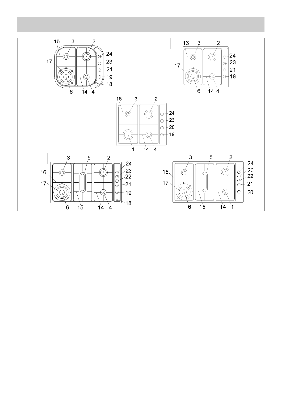
DESCRIPTION OF THE HOT PLATES
1) Large burner (Left front) of 11.2 MJ (3100 W)
2) Medium burner (Right rear) of 10.2 MJ (2950 W)
3) Small burner (Left rear) of 4.9 MJ (1450 W)
4) Auxiliar burner (Right front) of 4.0 MJ (1050 W)
5) Fish burner (Center) of 9.2 MJ (2600 W)
6) Ultra rapid burner (Left front) of 14.0 MJ (4000 W)
14) Right trivet
15) Center trivet
16) Left trivet
17) Trivet for ultra rapid burner
18) Eletric ignition push-button
19) Burner control knob n° 4
20) Burner control knob n° 1
21) Burner control knob n° 6
22) Burner control knob n° 5
23) Burner control knob n° 3
24) Burner control knob n° 2
24658 G-m
24968 G-m
Page 3
3
1) BURNERS
Ensure that all gas supply connections are correct
and that supply valves are open.
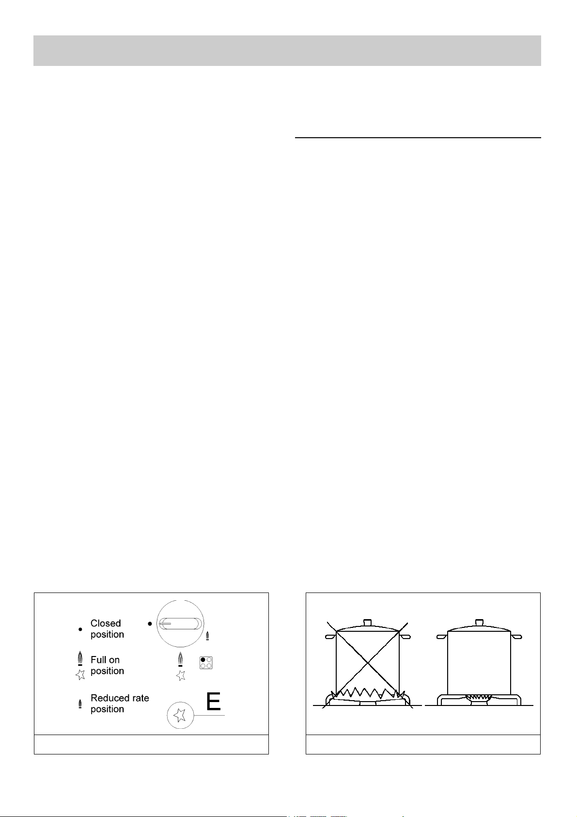
The burner controls are engraved graphically to
indicate their associated burner and setting.
- MANUAL IGNITION (FIG. 1)
Select desired hotplate burner, depress control
knob and gently turn anti-clockwise to “Full on”
position whilst applying a lighted match to the
burner. After the flame has established, adjust
burner to desired setting.
- ELECTRIC IGNITION (FIG. 1)
Select desired burner, depress control knob and
gently turn anti-clockwise to “Full on” position whilst
depressing the electronic ignition switch (E) until
flame has established.
After the flame has established, select the required
setting.
- AUTOMATIC ELECTRICAL IGNITION (FIG. 1)
Select desired burner, turn the control knob anticlockwise to “Full on” position, then depress it. After
the flame has established, adjust burner to desired
setting.
- SWITCHING ON BURNERS EQUIPPED WITH
FLAME FAILURE DEVICE (FIG. 1)
The knobs of burners equipped with flame failure
device must be turned in an anticlockwise direction
until they reach the “Full on” position (large flame
fig. 1) and come to a stop. Now depress the knob in
question and repeat the previously indicated
operations. Keep the knob depressed for about 10
seconds once the burner has ignited.
NOTE:
WHEN THE CONTROL OF THE DOUBLE RING
BURNER IS SET TO MINIMUM THE OUTER
FLAME ONLY REMAINS ALIGHT.
HOW TO USE THE BURNER HOTPLATES
In order to maximize the efficiency of the burners
the following pan sizes are recommended:
BURNER PAN DIAMETER
Wok burner 22 - 24
Large burner 20 - 22
Medium burner 20 - 22
Small burner 16 - 18
Auxiliary burner 10 - 14
Fish burne (WIDTH) 12 - 20
(LENGTH) 30 - 40
Suggestions:
- When boiling point is reached, it is beneficial to
turn the control knob to the “LOW” setting.
- When possible, use pans with correctly fitting lids.
- Always use pans of the correct diameter (Fig. 2).
USE
FIG. 1 FIG. 2
Page 4
4
USE
WARNING - SAFETY:
- BURNERS WITH FLAME FAILURE DEVICE
MAY ONLY BE IGNITED WHEN THE RELATIVE
KNOB HAS BEEN SET TO THE FULL ON
POSITION (LARGE FLAME FIG.1).
- NEVER ALLOW CHILDREN TO PLAY NEAR
THE APPLIANCE WHEN USING THE
BURNERS. CHECK THAT THE PAN HANDLES
ARE POSITIONED CORRECTLY.
- DO NOT SPRAY AEROSOLS IN THE VICINITY
OF THE HOTPLATES WHILE THE APPLIANCE
IS IN USE.
- FOR SAFETY ENSURE THAT NO FLAMMABLE
OR THERMALLY DEFORMABLE OBJECTS
ARE PLACED DIRECTLY BELOW THE HOB.
- WHERE THIS APPLIANCE IS INSTALLED IN A
MARINE CRAFT OR A CARAVAN, IT SHALL
NOT BE USED AS A SPACE HEATER.
- FOR MAXIMUM STABILITY ALWAYS USE A
ROUND BOTTOM WOK.
- IF GAS BURNS WITH A YELLOW FLAME, DO
NOT CONTINUE TO USE BURNER AND
ARRANGE FOR SERVICE.
- OBSERVE SAFE CLEARANCES AROUND
APPLIANCE.
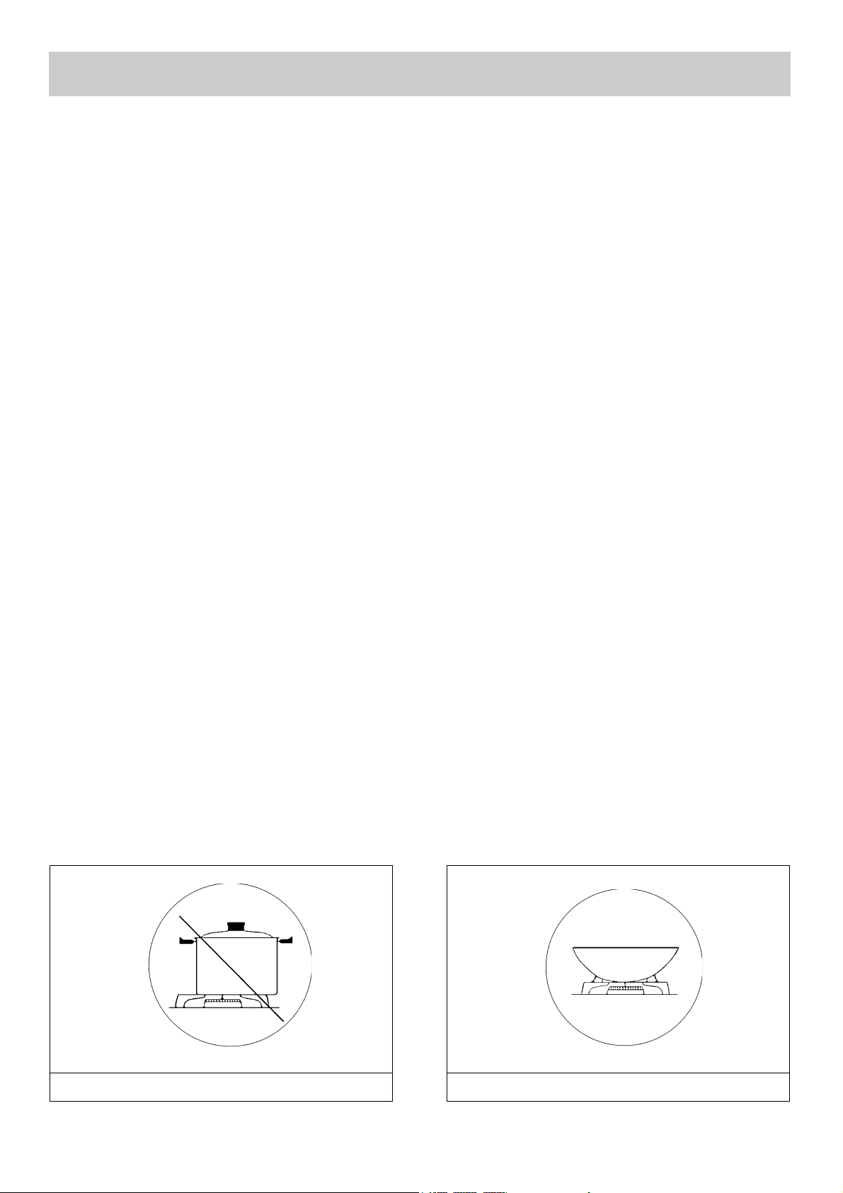
- LOCATE PAN CENTRALLY OVER THE
BURNER SO THAT IS STABLE AND DOES
NOT OVERHANG THE APPLIANCE (FIG. 3).
- USE ONLY A WOK SUPPORT SUPPLIED OR
RECOMMENDED BY THE MANUFACTURER
OF THE APPLIANCE (FIG. 4).
- THE APPLIANCE IS NOT INTENDED FOR USE
BY YOUNG CHILDREN OR INFIRM PERSONS
WITHOUT SUPERVISION.
- YOUNG CHILDREN SHOULD BE SUPERVISED
TO ENSURE THAT THEY DO NOT PLAY WITH
THE APPLIANCE.
- DO NOT STORE OR USE GASOLINE OR
OTHER FLAMMABLE VAPOURS, LIQUIDS OR
ITEMS IN THE VICINITY OF THIS OR ANY
OTHER APPLIANCE.
In the event of bad working of the hob, (there
are no mentions on the instruction book) the
user must apply to the servicing “AEG”
imparting both the “ENR” and “FNR” numbers
stamped on the data label put on the bottom of
the hob.
The above numbers give the technician the
possibility to find the proper spare parts with a
consequent timely assistance. For an easy
finding, we suggest to write the above “ENR”
and “FNR” numbers on the beneath blanks.
ENR: .......................................................................
FNR: .......................................................................
FIG. 3 FIG. 4
Page 5

5
WARNING:
Do not wash any part while it is still hot.
2) HOTPLATE
Periodically, the enamelled trivets, burners and
burner caps should be washed with warm soapy
water (fig. 5).
Ensure they are completely dry and that all holes in
the burners are clear of obstructions prior to reassembly.
SHOULD THE BURNER CONTROL KNOBS
BECOME DIFFICULT TO OPERATE, THEN SEEK
APPLIANCE SERVICE.
3) ENAMELLED PARTS
To maintain the characteristic brightness of the
enamelled parts, it is necessary that they be
cleaned frequently with warm soapy water. Do not
clean them while they are hot and never use
abrasive powders or cleaners.
Stains may be removed by wiping with a clean cloth
and soapy water before stains become cold.
Stubborn stains may be removed by soaking in hot
soapy water.
Do not allow vinegar, coffee, milk, salty water,
lemon or tomato juice to remain in contact with
enamelled surfaces.
4) PARTS IN STAINLESS STEEL
Parts in stainless steel must be cleaned with warm
soapy water and dried with a clean soft cloth.
Frequent use of cleaning agents designed for
stainless steel is recommended.
CLEANING
FIG. 5
Page 6

TECHNICAL INFORMATION FOR
INSTALLATION PERSONNEL
WARNING:
This appliance must be installed only by
authorised personnel and in accordance with
AS5601 (AG 601), the manufacturers installation
instructions, relevant municipal building
regulations, gas and electrical authority
regulations.
The wall and bench surfaces must be capable of
sustaining temperatures of 75 degrees Celsius. All
laminates, fixing adhesive and surfacing materials
should be certified suitable for this temperature.
Refer to figure 6 for required clearances around
appliance.
NOTE 1 :
FIRE RESISTANT MATERIAL (eg CERAMIC
TILES) IS REQUIRED TO 450 mm ABOVE
BURNER TOP IF WALL OR VERTICAL
STRUCTURES ARE WITHIN 200 mm FROM
BURNER.
NOTE 2 :
RANGEHOOD AND EXHAUST SYSTEM ARE
NOT PERMITTED WITHIN 600 mm ABOVE
BURNER TOPS.
5) BENCHTOP CUTOUT
The cutout in the bench-top should be made using
the dimensions given in figure 7, 8 the template
provided.
NEVER LEAVE THE PACKING COMPONENTS
(PLASTIC BAGS, NAILS, FOAMED
POLYSTYRENE, ETC...) WITHIN THE REACH OF
THE CHILDREN SINCE THEY ARE A SOURCE
OF
POTENTIAL DANGER.
6) FIXING OF THE HOTPLATE
The hotplate is provided with a special seal to
prevent liquid penetrating to the underside of the
appliance.
For correct installation of this seal ensure the
procedures detailed below are followed:
- Unpack the sealing strips ensuring that the
transparent protection is not damaged and
remains attached to the seal.
- Invert the appliance and fix the special clamps to
the underside of the appliance with the screws “G”
(see fig. 9).
- Carefully place the seal around the outer edge of
the appliance. Care should be taken to align the
outer edge of the seal with that of the appliance.
Trim the seal to the correct length to ensure that
no overlap of the seal occurs. Refer figure 10.
- Adhere the seal to the appliance by pressing firmly
with fingers.
- Remove the protective strip from the seal.
- Place the appliance into the cutout in the benchtop and secure with the special screws and fixing
clamps. Refer figure 11.
- It’s necessary to fix a wooden division locked by
screws at a minimun distance of 50 mm from the
bottom of the hob if no oven is installed under the
hob, is advisable also, to provide for drawers
under the same.
FIG. 9 FIG. 10 FIG. 11
FIG. 6 FIG. 7 FIG. 8
6
INSTALLATION
Page 7

INSTALLATION
7
7) GAS CONNECTION
The gas connection is located at the rear and on the
underside of the appliance 100 mm from the right
hand side.
Natural Gas
Natural Gas installations require the connection of a
gas regulator at the appliance.
Assemble the regulator (noting the gas flow
direction) and transition pieces, in accordance with
figure 12.
THE APPLIANCE HAS BEEN FITTED WITH
INJECTORS DESIGNED FOR NATURAL GAS.
LPG (liquified petroleum gas) INJECTORS HAS
BEEN SUPPLIED.
Liquefied Petroleum Gas
In a LPG installation the gas regulation is made at
the gas cylinder and regulation at the appliance is
not required. To connect supply to the appliance
use transition pieces as shown in figure 13.
These pieces are supplied with the appliance on
purchase.
8) ELECTRICAL CONNECTION
The appliance is supplied with a 1800 mm long
flexible supply lead.
The point of attachment for this lead is located at
the rear and on the underside of the appliance 380
mm from the right hand side.
The voltage and power consumption are detailed on
the underside of the appliance. Ensure that the
appliance is correctly rated to the supply.
Connect appliance by way of a switched power
point.
THE APPLIANCE MUST BE EARTHED. Ensure
that this power point is properly earthed.
Look at the connection wiring diagrams (fig.14, 15,
16 and fig. 17).
FIG. 15 FIG. 16 FIG. 17
FIG. 12 FIG. 13 FIG. 14
Page 8

8
REGULATION
Warning:
Adjustment of this appliance shall only be
carried out only by authorised personnel.
9) BURNERS
PRIMARY AIR ADJUSTMENT (refer figure 18)
- Turn off power and unplug electric lead from
power point.
- Remove the knobs “M”.
- Unscrew the screws “V”.
- Lift the control panel.
Ignite the burners and adjust the sleeves “B” (refere
figure 19 and table in the next page) to obtain the
desired flame. Ensure that locking screws “A” are
retightened.
10) CONTROL VALVES
“Reduced rate” adjustment
The control valves are suitable for all types of
gases.
They are the male cone type allowing one direction
of flow.
Simmer flame adjustment (refer figure 20)
- Light burner and set to low setting.
- Remove control knob (friction fit).
- Insert a small screwdriver into the hollow stem of
the valve and adjust the flame to the desired level.
- Ensure that flame is stable when the controls are
rapidly moved from low to maximum.
NOTE:
Adjustment may be necessary when the
appliance is connected to Natural Gas. When
connected to LPG the valve cone should be
screwed down completely.
FIG. 18 FIG. 19
FIG. 20
Page 9

N°
DESCRIPTION
MJ/h W
9
CONVERSIONS
BURNER ARRANGEMENT ON THE HOB
HEAT
INPUT
BURNERS
GAS
LARGE Propane 2.75 9.00 90 11.2 3100
1
LEFT FRONT Natural 1.00 9.00 150 11.2 3100
MEDIUM Propane 2.75 9.00 90 10.2 2950
2
RIGHT REAR Natural 1.00 9.00 145 10.2 2950
SMALL Propane 2.75 9.00 60 4.9 1450
3
LEFT REAR Natural 1.00 9.00 100 4.9 1450
AUXILIARY Propane 2.75 1.00 50 4.0 1050
4
RIGHT FRONT Natural 1.00 9.00 90 4.0 1050
FISH BURNER Propane 2.75 9.00 83 9.2 2600
5
CENTER Natural 1.00 9.00 136 9.2 2600
WOK BURNER Propane 2.75 complete 102 14.0 4000
6
LEFT FRONT Natural 1.00 complete 170 14.0 4000
TABLE
PRIMARY AIR
CLEARANCE “S”
(FIG. 19)
mm
DIAMETER
INJECTORS
1/00 mm
OPERATING
PRESSURE
kPa
Warning:
Conversion of this appliance shall only be
carried out only by authorised personnel.
11) REPLACEMENT OF INJECTORS
The burners are suitable for use with different gases.
To adjust to different gases it is necessary to change
the injectors.
A range of injectors are supplied with the appliance.
PROCEDURES
Removal of injectors
- Remove control panel (refer section 9).
- Loosen screw “A” and slide sleeve “B”, away from
control valve (refer figure 21).
- Loosen the injector with the ring spanner “M” (refer
figure 22).
- Unscrew the injector with the open ended spanner
until there is clearance for the spring hook “P”, to
engage the injector.
- Unscrew the injector completely.
Re-installation of injectors
- Select the correct injector.
- Hold injector with spring and offer it to the control
valve.
- Use spanner “M”, to engage the threads.
- Remove spring “P”.
- Tighten injector with ring spanner “M”.
The technical details of the operating pressures,
injector diameters and rating for various gases are
scheduled below.
FIG. 21 FIG. 22
Page 10

10
MAINTENANCE
Warning:
Maintenance, service and repairs of this
appliance shall only be carried out only by
authorised personnel.
12) REPLACEMENT OF COMPONENTS
NOTE:
BEFORE ANY MAINTENANCE REQUIRING
REPLACEMENT OF A COMPONENT IS
UNDERTAKEN ENSURE THAT THE
ELECTRICAL LEAD HAS BEEN ISOLATED AND
REMOVED FROM THE POWER POINT.
Components internal to the appliance (refer
figure 23 or 24)
- Disassemble the control panel as described in
section 9.
- Remove screw “A”, located beneath the control
panel and the screws “B”, fixing the burner base to
the top of the appliance.
- Remove burner base "T" and washers “G”.
- Unscrew the threaded ring locking “D” the wok
burner.
- Remove the three plastic screws “O” at the rear of
the appliance (86 cm models only).
- Unscrew the center screw that lock the hotplate
(86 cm models only).
- Separate the top and bottom portions of the
appliance.
- When reassembling the hotplate it is important
that the control panel end is slightly elevated until
the left hand end engages the metal tags on the
under body. Push the hotplate to the left, lower
and secure the screws (refer figure 25).
Replacement of electric cable
- Should the flexible supply lead need replacement
it is essential that one of the correct rating and
construction be used. The lead must contain an
earth and this must be connected.
Burner replacement (refer figure 26)
- Disassemble the appliance as detailed above.
- Remove screws "R" and plate "P".
- Unscrew burner body "M".
- Reassemble all the pieces in the inverse order of
disassembly.
Control valve replacement (refer fig. 27 - 28)
- Disassemble the appliance as detailed above.
- Remove eventual microswitches (refer "S").
- Remove screws “R” and “V”. This valve “A” is free
for removal.
- It is recommended that the sealing washer “D” be
replaced whenever a valve is removed.
Control valve greasing (referes 29 - 30)
- Greasing of the valves is necessary if they
become difficult to turn.
- Remove the securing screws and disassemble the
valve.
- Clean the valve cone and housing with a cloth
soaked in thinners.
- Lightly grease the cone.
- Reassemble the valve ensuring that all excess
grease is removed and that the valve is free of
obstructions.
- Reassemble the valve unit.
FIG. 23
FIG. 26
FIG. 25FIG. 24
FIG. 27 FIG. 28
Page 11

HOT PLATES TECHNICAL DATA
11
FIG. 29 FIG. 30
PRESSURE
PROPANE
NATURAL
3 + 1 WOK BURNERS
“SOFT”
3 + 1 WOK BURNERS
“RECTANGULAR”
24658 G-m
4 BURNERS
(NO WOK)
“RECTANGULAR”
2.75 kPa
1.00 kPa
2.75 kPa
1.00 kPa
2.75 kPa
1.00 kPa
TOT. HEAT INPUT
TOT.NOMINAL CONSUMP.
0.6 W
0.6 W 0.6 W
PROPANE
NATURAL
33.1 MJ/h
33.1 MJ/h
33.1 MJ/h
33.1 MJ/h
30.3 MJ/h
30.3 MJ/h
VOLTAGE
FREQUENCY
240 V ~
50 Hz
240 V ~
50 Hz
240 V ~
50 Hz
PRESSURE
PROPANE
NATURAL
4 + 1 WOK BURNERS
“RECTANGULAR”
4 + 1 WOK BURNERS
“RECTANGULAR”
24968 G-m
TOT. HEAT INPUT
TOT.NOMINAL CONSUMP.
PROPANE
NATURAL
42.3 MJ/h
42.3 MJ/h
49.5 MJ/h
49.5 MJ/h
VOLTAGE
FREQUENCY
240 V ~ 240 V ~
50 Hz
50 Hz
2.75 kPa
1.00 kPa
2.75 kPa
1.00 kPa
0.6 W
0.6 W
Page 12

ANDI-CO
AUSTRALIA PTY LTD
ABN 68 005 899 365
12
Melbourne Head Office:
1 Stamford Road, OAKLEIGH VIC 3166
Tel: (03) 9569 1255, Fax: (03) 9569 1450
Sydney Office:
97 Rose Street, CHIPPENDALE NSW 2008
Tel: (02) 9380 8444
Brisbane Office:
Unit 2/44 Leonard Street, WOOLLOONGABBA QLD 4102
Tel: (07) 3891 2499, Fax: (07) 3891 2495
Adelaide Office:
106A Rundle Street, KENT TOWN SA 5067
Tel: (08) 8132 1600, Fax: (08) 8132 1655
For Service Phone: 1300 650 020 (in Australia)
Spare Parts Tel: (03) 9569 7744
www.andico.com.au
 Loading...