

Page 1

2000 D
Dunstabzugshaube
Fume Extractor Hood
Montage- und Gebrauchsanweisung
Installation and Operating Instructions
Page 2

ContentsContents
Contents
ContentsContents
IntroductionIntroduction
Introduction
IntroductionIntroduction
Extractor version 28
Filter version 29
Electrical connectionsElectrical connections
Electrical connections
Electrical connectionsElectrical connections
Safety warnings for electrician 30
TT
echnic Detailsechnic Details
T
echnic Details
TT
echnic Detailsechnic Details
InstallationInstallation
Installation
InstallationInstallation
Safety warnings for kitchen unit installer 32
Installation 34
Safety warnings for user 38
VV
iew of the hoodiew of the hood
V
iew of the hood
VV
iew of the hoodiew of the hood
Hood OperationHood Operation
Hood Operation
Hood OperationHood Operation
Setting the fan speed 40
Hood lighting 40
Intensive speed P 41
Fan timer 41
Switching off the fan 42
2828
28
2828
3030
30
3030
3131
31
3131
3232
32
3232
3939
39
3939
3939
39
3939
Maintenance and careMaintenance and care
Maintenance and care
Maintenance and careMaintenance and care
Warnings on the activated carbon filter 43
Display warning on saturation of activated carbon filter 44
Display warning on saturation of metal grease filter 46
Warning 48
Replacing light bulbs 48
CleaningCleaning
Cleaning
CleaningCleaning
Special accessorySpecial accessory
Special accessory
Special accessorySpecial accessory
TT
echnical assistance serviceechnical assistance service
T
echnical assistance service
TT
echnical assistance serviceechnical assistance service
4343
43
4343
4949
49
4949
4949
49
4949
4949
49
4949
27
Page 3

IntroductionIntroduction
Introduction
IntroductionIntroduction
Extractor versionExtractor version
Extractor version
Extractor versionExtractor version
●The hood is supplied as an extractor unit and can also be
used with a filtering function by fitting activated carbon
filters (special accessory).
● You will need original AEG activated carbon filters for this
function (see Special Accessories).
● The air is forced out through a hose fitted to the
connection flange
● The outlet hose must have a diameter of 150 mm (special
accessory) for the filtering version.
● If the cooking vapour is passed through an outside
wall, you will need an MKZ150 telescopic wall pipe
E-Nr.: 942 118 609 (150 mm Ø) from our range of
special accessories.
28
Page 4

Filter versionFilter version
Filter version
Filter versionFilter version
● The air is filtered through an activated carbon filter and
passed back into the kitchen through the top outlet duct
grids. This type of operation is chosen when there is no
outlet connection to the outside or when it is not possible
to install one. You will need to ask your supplier or
technical assistance centre for an activated carbon filter
for this type of operation, stating the hood model for
which it is required.
● You will need an original AEG KF2000 activated carbon
filter for the filtering function. (See Special Accessories).
● Unplug the unit or disconnect it from the power supply
● Remove the metal grease filters.
● Unscrew the two carbon filter frame screws and insert the
active carbon filter in the support.
● Re-close the carbon filter frame using the same screws
● Refit the metal grease filters.
Fig. 1Fig. 1
Fig. 1.
Fig. 1Fig. 1
Fig. 2Fig. 2
Fig. 2.
Fig. 2Fig. 2
Fig. 1Fig. 1
Fig. 1
Fig. 1Fig. 1
Fig. 2Fig. 2
Fig. 2
Fig. 2Fig. 2
29
Page 5

Electrical connectionsElectrical connections
Electrical connections
Electrical connectionsElectrical connections
Safety warnings for electricianSafety warnings for electrician
Safety warnings for electrician
Safety warnings for electricianSafety warnings for electrician
Check that the power supply voltage shown on the rating
plate corresponds to the mains supply before proceeding
to make any electrical connections. If the unit is supplied
ready-fitted with a plug, it can be connected to any easily
accessible socket installed in compliance with the
regulations in force.
If a fixed connection is required, the hood must be
installed exclusively by an electrician registered with the
local electrical company. The hood should be installed
using an omnipolar switch with contacts that open to at
least 3 mm.
Fused switches can be used for this purpose (with
cartridge fuses that can be extracted from the fuse
holder), as can automatic circuit breakers and contactors
which open to more than 3 mm.
We decline all responsibility for any problems or faults
caused by a failure to observe the above instructions.
30
If the power socket is positioned directly above the
extractor hood or on the chimney cover this will give two
advantages:
1. The socket cannot be seen.
2. The unit can be disconnected whenever required by
simply taking out the plug.
Electrical connectionsElectrical connections
Electrical connections
Electrical connectionsElectrical connections
220-230 V - using fixed power supply line with plug.
(The unit should only be connected up by an authorized
electrician).
Page 6

TT
echnic Detailsechnic Details
T
echnic Details
TT
echnic Detailsechnic Details
Dimensions:
Height x Width x Depht (in cm) 84-134 x 89,8 x 51
Weight: Net: Gross:
22,3 kg 29 kg
Maximum absorbed power: 240 W
Motor absorption: 1 x 215 W
Lighting: 2 x 9 W
Length of the cable: 120 cm
Fan powers (speed), speed in compliance with DIN 44971
Extractor version: min. max. Int.
199 m
Filter version: min. max. Int.
123 m3/h 265 m3/h 290 m3/h
Exhaust pipe 150 mm Ø
3
/h 414 m3/h 570 m3/h
31
Page 7

InstallationInstallation
Installation
InstallationInstallation
Safety warnings for kitchen unit installerSafety warnings for kitchen unit installer
Safety warnings for kitchen unit installer
Safety warnings for kitchen unit installerSafety warnings for kitchen unit installer
● When used as an extractor unit, the hood must be fitted
with a 150mm diameter hose.
● If the fumes must be forced out through the wall, you
must obtain a MKZ150 sizable wall exhaust pipe (with
external exhaust and air intake), E-Nr.- 942 118 609 (Ø
150 mm) which is one of our optional parts.
When installing the hood, make sure you respect theWhen installing the hood, make sure you respect the
●
When installing the hood, make sure you respect the
When installing the hood, make sure you respect theWhen installing the hood, make sure you respect the
following minimum distance from the top edge of thefollowing minimum distance from the top edge of the
following minimum distance from the top edge of the
following minimum distance from the top edge of thefollowing minimum distance from the top edge of the
cooking hob/ring surfaces:cooking hob/ring surfaces:
cooking hob/ring surfaces:
cooking hob/ring surfaces:cooking hob/ring surfaces:
electric cookerselectric cookers
electric cookers
electric cookerselectric cookers
gas cookersgas cookers
gas cookers
gas cookersgas cookers
coal and oil cookerscoal and oil cookers
coal and oil cookers
coal and oil cookerscoal and oil cookers
● The air outlet must not be connected to chimney flues or
combustion gas ducts. The air outlet must under no circumstances be connected to ventilation ducts for rooms
in which fuel-burning appliances are installed.
● It is advisable to apply for authorization from the
relevant controlling authority when connecting the outlet
to an unused chimney flue or combustion gas duct.
The air outlet installation must comply with the
regulations laid down by the relevant authorities.
● When the unit is used in its extractor version, a
sufficiently large ventilation hole must be provided, with
dimensions that are approximately the same as the outlet
hole.
● National and regional building regulations impose a
number of restrictions on using hoods and fuel-burning
appliances connected to a chimney, such as coal or oil
room-heaters and gas fires, in the same room.
● The national decree on fuel-burning systems specifies a
maximum depression of 0.04 bar in such rooms.
600 mm600 mm
600 mm
600 mm600 mm
650 mm650 mm
650 mm
650 mm650 mm
700 mm min.700 mm min.
700 mm min.
700 mm min.700 mm min.
32
Page 8

● Hoods can only be used safely with appliances connected
to a chimney if the room and/or flat (air/environment
combination) is ventilated from outside using a suitable
ventilation hole approximately 500-600 cm2 large to
avoid the possibility of a depression being created during
operation of the hood.
If you have any doubts, contact the relevant controlling
authority or building inspector’s office.
● Since the rule for rooms with fuel burning appliances is
“outlet hole of the same size as the ventilation hole”, a
hole of 500-600 cm2, which is to say a larger hole, could
reduce the performance of the extractor hood.
● If the hood is used in its filtering function, it will operate
simply and safely in the above conditions without the
need for any of the aforementioned measures.
● When the hood is used in its extractor function, the
following rules must be followed to obtain optimal
operation:
— short and straight outlet hose
— keep bends in outlet hose to a minimum
— never install the hoses with an acute angle, they must
always follow a gentle curve only
— keep the hose as large as possible (150 mm Ø).
● Failure to observe these basic rules will drastically reduce
the performance and increase the noise levels of the
extractor hood.
33
Page 9

InstallationInstallation
Installation
InstallationInstallation
● Rest the template correctly against the wall. The lower
corner of the template corresponds to the lower corner of
the extractor hood.
● A cross is marked
on the template
to indicate the
centre. Mark
this point on
the wall.
● Drill two holes (Ø 8 mm) in the
wall at the points indicated,
insert the stops (Ø 8 mm) and
screw in the hooks provided.
Fig. 3.Fig. 3.
Fig. 3.
Fig. 3.Fig. 3.
● Hang the hood and adjust its
position using the screws on the
hooks.
● The reference point “
marked on the body of the
extractor hood must coincide
with the line you have drawn
on the wall.
Fig. 3.Fig. 3.
Fig. 3.
Fig. 3.Fig. 3.
Fig. 4.Fig. 4.
Fig. 4.
Fig. 4.Fig. 4.
Fig. 3.Fig. 3.
Fig. 3.
Fig. 3.Fig. 3.
Fig. 4.Fig. 4.
Fig. 4.
Fig. 4.Fig. 4.
aa
a”
aa
Fig. 3Fig. 3
Fig. 3
Fig. 3Fig. 3
Fig. 4Fig. 4
Fig. 4
Fig. 4Fig. 4
●Once the extractor hood has been correctly aligned,
remove the grease filter.
34
Page 10
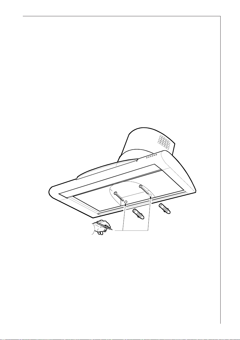
● From inside the hood, mark the final points at which the
hood has to be fixed to the wall.
Fig. 5.Fig. 5.
Fig. 5.
Fig. 5.Fig. 5.
(to reach these points it will be necessary to remove
activated carbon filter frame until the filter itself is
replaced - see
Fig. 2Fig. 2
Fig. 2).
Fig. 2Fig. 2
● Remove the hood.
● Drill 2 holes (Ø 8 mm) and insert the plugs (Ø 8 mm).
Fig. 5.Fig. 5.
Fig. 5.
Fig. 5.Fig. 5.
●Hang the extractor hood up again.
● Fix the hood into its final position using 2 screws
(Ø 5x45 mm).
Fig. 5.Fig. 5.
Fig. 5.
Fig. 5.Fig. 5.
Fig. 5Fig. 5
Fig. 5
Fig. 5Fig. 5
35
Page 11

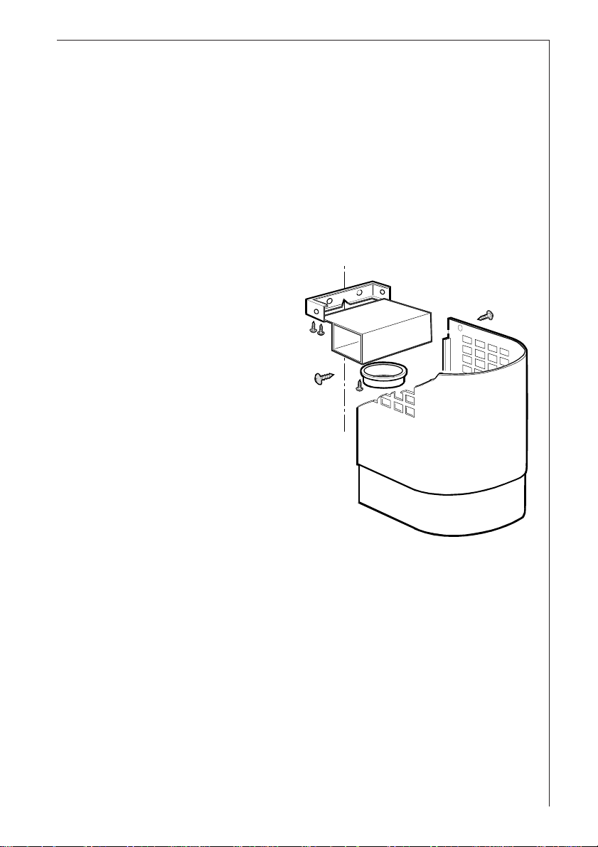
● Remove the telescopic chimney support
the side screws
kept).
Fig. 6Fig. 6
Fig. 6.
Fig. 6Fig. 6
● Remove the air pipe
support
MM
M; to do this, unscrew the four screws (Ø 2,9 x
MM
RR
R (one on each side - these screws must be
RR
LL
L from the telescopic chimney
LL
MM
M by unscrewing
MM
9,5 mm) fixing the air pipe to the support (these screws
must be kept).
Fig. 6Fig. 6
Fig. 6.
Fig. 6Fig. 6
● Fit the telescopic chimney support to the wall, at a point
close to the ceiling. The telescopic chimney support has a
reference mark
you have already drawn on the wall.
PP
P, which must coincide with the line that
PP
Fig. 6Fig. 6
Fig. 6.
Fig. 6Fig. 6
● Using a pencil, mark the two holes required to fix the
support, and drill the holes (Ø 8 mm).
● Insert two plugs and fix the telescopic chimney support
using 2 screws size (5x45 mm).
Fig. 6Fig. 6
Fig. 6.
Fig. 6Fig. 6
Fig. 6 Fig. 6
Fig. 6.
Fig. 6 Fig. 6
MM
M
MM
● During installation the plug must not be connected to the
power supply.
M
36
M
P
R
R
L
R
R
Fig. 6Fig. 6
Fig. 6
Fig. 6Fig. 6
Page 12
Select the hood operating mode
●●
Extractor operationExtractor operation
●
Extractor operation
●●
Extractor operationExtractor operation
Fix the 150 mm diameter ABS pipe to the hood outlet and
ensure that the other end discharges into the open air.
The hood is supplied with a reducer for 120 mm diameter
pipes. This reducer must be mounted on the hood outlet.
●●
Filter operationFilter operation
●
Filter operation
●●
Filter operationFilter operation
If the connector ring has not yet been installed, it must be
fitted at this point (
Fig. 7Fig. 7
Fig. 7, bayonet
Fig. 7Fig. 7
QQ
Q in
QQ
connector). Turn it in a
clockwise direction and
fix it to the air pipe L
using a screw. Insert the
air pipe into the
Q
telescopic chimney
support and fix it with
L
four screws (Ø 2,9 x 9,5
Fig. 7Fig. 7
mm).
Fig. 7.
Fig. 7Fig. 7
Fix the 150 mm diameter
ABS pipe to the hood
outlet, and connect it to
the air pipe connector
Fig. 7Fig. 7
Fig. 7
ring.
Fig. 7Fig. 7
For both versions:
● The hood can now be connected to the power supply.
● If a gas non-return valve has been installed or is required,
ensure that it opens and closes properly.
● Fix the top part the telescopic outlet pipe to the relative
R.R.
support, using the two 3 mm dia x 9 mm screws
R.
R.R.
Fig. 6.Fig. 6.
Fig. 6.
Fig. 6.Fig. 6.
● Slide the bottom part of the telescopic outlet pipe
downward until it rests in its housing on the top of the
hood.
● Replace the grease filters.
37
Page 13
Safety warnings for userSafety warnings for user
Safety warnings for user
Safety warnings for userSafety warnings for user
● Never leave a cooking hob or ring on without a pot
or pan on top of it, to avoid the possibility of excess
heat damaging the unit. Gas, oil or coal cooker
flames in particular should never be left uncovered.
● Special care should be taken when using deep fat
fryers since the oil in them can overheat and burst
into flames.
● The risk of a fat fire increases when using dirty oil.
● It is extremely important to note that overheating
can cause a fire.
Never carry out any flambé cooking under theNever carry out any flambé cooking under the
●
Never carry out any flambé cooking under the
Never carry out any flambé cooking under theNever carry out any flambé cooking under the
hood.hood.
hood.
hood.hood.
Always disconnect the unit from the power supplyAlways disconnect the unit from the power supply
●
Always disconnect the unit from the power supply
Always disconnect the unit from the power supplyAlways disconnect the unit from the power supply
before carrying out any work on the hood,before carrying out any work on the hood,
before carrying out any work on the hood,
before carrying out any work on the hood,before carrying out any work on the hood,
including replacing the light bulbincluding replacing the light bulb
including replacing the light bulb (take the
including replacing the light bulbincluding replacing the light bulb
cartridge fuse out of the fuse holder or switch off
the automatic circuit breaker).
38
It is very important to clean the hood and replaceIt is very important to clean the hood and replace
●
It is very important to clean the hood and replace
It is very important to clean the hood and replaceIt is very important to clean the hood and replace
the filter at the recommended intervals. Failurethe filter at the recommended intervals. Failure
the filter at the recommended intervals. Failure
the filter at the recommended intervals. Failurethe filter at the recommended intervals. Failure
to do so could cause grease deposits to build up,to do so could cause grease deposits to build up,
to do so could cause grease deposits to build up,
to do so could cause grease deposits to build up,to do so could cause grease deposits to build up,
causing a fire hazard.causing a fire hazard.
causing a fire hazard.
causing a fire hazard.causing a fire hazard.
Page 14

VV
iew of the hoodiew of the hood
V
iew of the hood
VV
iew of the hoodiew of the hood
1.1.
1 . Control panel
1.1.
2.2.
2 . Lighting units
2.2.
3.3.
3 . Metal grease filters
3.3.
4.4.
4 . Telescopic chimney
4.4.
5.5.
5 . Outlet grids for
5.5.
Filter version
Hood OperationHood Operation
Hood Operation
Hood OperationHood Operation
Bild 8Bild 8
Bild 8
Bild 8Bild 8
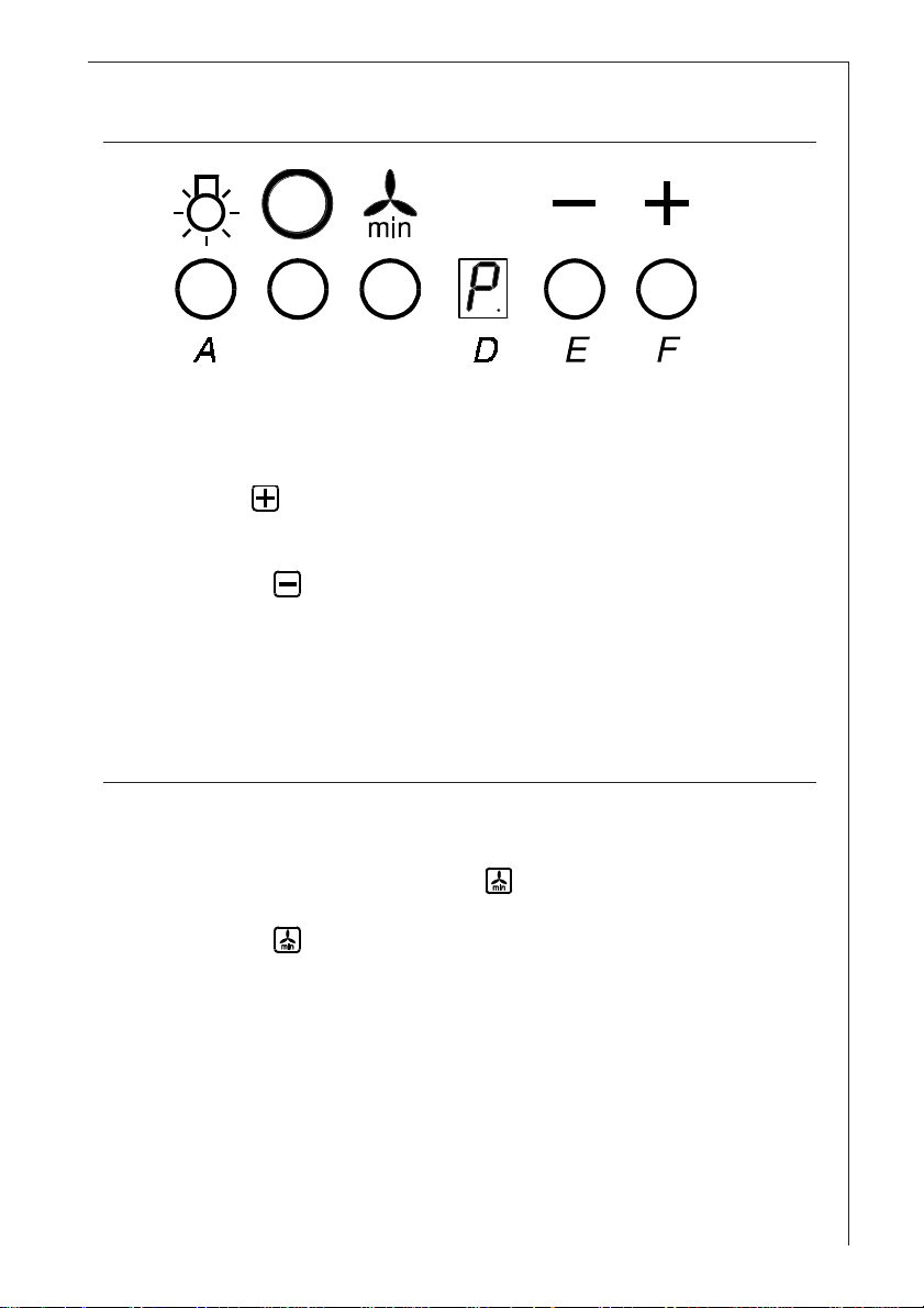
● The control panel is located on the front of the hood.
● The control panel numbers and symbols (
to right) are explained in the key below:
= Lighting, on/off.
= Fan switch (speeds 1-9).
2
3
4
1
3
Fig. 8Fig. 8
Fig. 8 from left
Fig. 8Fig. 8
5
3
= Fan timer, 15 minutes.
= Display showing fan speed (1-9), high speed (P),
change grease filters (F) and change activated
carbon filters (C).
= Decrease fan speed button for reducing speed of
motor from high speed (P) down to speed 1.
= Increase fan speed button for increasing speed of
motor from 1 to 9 and high speed (P).
● If the hood fails to operate correctly, briefly disconnect it
from the mains power supply for almost 5 sec. by pulling
out the plug. Then plug it in again and try once more
before contacting the Technical Assistance Service.
●●
Always press the Always press the
●
Always press the
●●
Always press the Always press the
from the mains supplyfrom the mains supply
from the mains supply
from the mains supplyfrom the mains supply
key before disconnecting the hood key before disconnecting the hood
key before disconnecting the hood
key before disconnecting the hood key before disconnecting the hood
..
.
..
39
Page 15

Setting the fan speedSetting the fan speed
Setting the fan speed
Setting the fan speedSetting the fan speed
Fig. 9Fig. 9
Fig. 9
Fig. 9Fig. 9
● Press the ( ) button (F) to select the fan speed from 1 to
9, keeping it pressed until the speed you want, e.g. speed
5, is shown on the display (D).
● The red display LED (D) will come on.
● If you accidentally set a higher speed than you want,
press the decrease speed button (
speed is shown on the display (D).
Fig. 9Fig. 9
Fig. 9.
Fig. 9Fig. 9
) (E) until the correct
Fig. 9Fig. 9
Fig. 9.
Fig. 9Fig. 9
Hood lightingHood lighting
Hood lighting
Hood lightingHood lighting
● Simply press the ( ) button (A) to switch the lighting on
or off.
40
Fig. 9Fig. 9
Fig. 9.
Fig. 9Fig. 9
Page 16
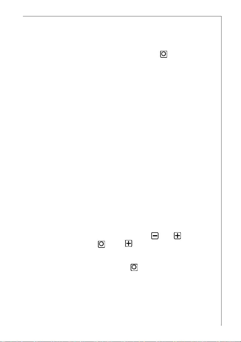
Intensive speed PIntensive speed P
Intensive speed P
Intensive speed PIntensive speed P
Fig. 10Fig. 10
Fig. 10
Fig. 10Fig. 10
● To select the intensive speed (P), press the increase speed
button ( ) (F) until the letter P (high speed) is shown on
the display (D).
Fig. 10Fig. 10
Fig. 10.
Fig. 10Fig. 10
● Press the (
speed operation. The speeds 9-1 will once again be shown
on the display.
Fan timerFan timer
Fan timer
Fan timerFan timer
● The hood should always be switched on before you start
cooking and left on for approximately 15 minutes after
you have finished (fan timer ).
● Press the ( ) button (C) to switch on the fan timer. I will
automatically switch off after 15 minutes operation at the
speed you have selected. A red dot will flash on and off
on the display (D).
) button (E) to slow down from intensive-
Fig. 10Fig. 10
Fig. 10.
Fig. 10Fig. 10
Fig. 10Fig. 10
Fig. 10.
Fig. 10Fig. 10
41
Page 17

Switching ofSwitching of
Switching of
Switching ofSwitching of
● Press the key (B) to switch off the fan at any speed
including P.
f the fan (Figures 10 - 11)f the fan (Figures 10 - 11)
f the fan (Figures 10 - 11)
f the fan (Figures 10 - 11)f the fan (Figures 10 - 11)
Fig. 11Fig. 11
Fig. 11.
Fig. 11Fig. 11
Fig. 11Fig. 11
Fig. 11
Fig. 11Fig. 11
● After 5 seconds the number “0” (
on the display (D) followed, finally, by only the red dot.
Fig. 12Fig. 12
Fig. 12.
Fig. 12Fig. 12
Fig. 12Fig. 12
Fig. 12
Fig. 12Fig. 12
Fig. 11Fig. 11
Fig. 11) will be shown
Fig. 11Fig. 11
42
Page 18

Maintenance and careMaintenance and care
Maintenance and care
Maintenance and careMaintenance and care
WW
arnings on the activated carbon filterarnings on the activated carbon filter
W
arnings on the activated carbon filter
WW
arnings on the activated carbon filterarnings on the activated carbon filter
● The activated carbon filter should be replaced at least
once every 120 operating hours.
● The activated carbon filter cannot be cleaned or reused.
● The effective elimination of cooking odours depends on
the functional adaptation of the volume of activated
carbon to the hood’s air flow and a carefully determined
position of the filter inside the hood.
● This combination inevitably decreases the air flow
compared to the extractor version.
● A decisive parameter for the elimination of cooking
odours is what is known as the “residence time” of the air
sucked into the hood in the activated carbon filter.
● The correct “residence time” can only be obtained using
original AEG activated carbon filters (see Special
Accessories).
43
Page 19

Display warning on saturation of activatedDisplay warning on saturation of activated
Display warning on saturation of activated
Display warning on saturation of activatedDisplay warning on saturation of activated
carbon filtercarbon filter
carbon filter
carbon filtercarbon filter
● After 120 operating hours, the letter (C) (activated carbon
filter) will flash on and off on the display (D) in
alternation with the fan speed setting.
Fig. 13Fig. 13
Fig. 13
Fig. 13Fig. 13
● This means the activated carbon filter needs to be
changed! (This operation should be carried out every 120
operating hours!).
Fig. 13Fig. 13
Fig. 13.
Fig. 13Fig. 13
● Warning! The metal grease filters must be cleaned when
you change the activated carbon filter.
44
Page 20
● Proceed as follows to remove and change my activated
carbon filter:
● Switch of the fan motor by pressing the
button.
● Take the precaution of removing my cartridge fuses from
their fuse holders or tripping my automatic circuit
breaker to ensure the fan motor cannot be switched on
accidentally.
● The activated carbon filter cannot be cleaned or reused.
●●
● Remove the metal filters.
●●
● Unscrew the two screws on the activated carbon filter
frame and remove the old filter.
●●
● Clean the inner housing using a hot detergent solution
●●
Fig. 2Fig. 2
Fig. 2.
Fig. 2Fig. 2
only (never use caustic detergents, abrasive powders or
brushes).
Mounting the carbon filter:Mounting the carbon filter:
Mounting the carbon filter:
Mounting the carbon filter:Mounting the carbon filter:
● Insert a new activated carbon filter into the carbon filter
frame.
Fig. 2Fig. 2
Fig. 2.
Fig. 2Fig. 2
● Close the activated carbon filter frame again using the
two screws provided.
●●
● Refit the metal filters.
●●
●●
● Screw the fuses back in or reset the automatic circuit
●●
breaker.
●●
● Proceed as follows to reset the filter saturation display
●●
(counter): Select any fan speed using
and then press the
B and F buttons at the same
E or F buttons
time, continuing to hold them down for at least 3 seconds
until the flashing letter C stops being shown on the
display (D) and then press the
●●
● The activated carbon filter display is now ready for use
●●
button B.
again.
45
Page 21

Display warning on saturation of metal greaseDisplay warning on saturation of metal grease
Display warning on saturation of metal grease
Display warning on saturation of metal greaseDisplay warning on saturation of metal grease
filterfilter
filter
filterfilter
●After 30 operating hours the letter (F- grease filters) will
flash on and off on the display (D) in alternation with the
fan speed setting.
● This means that the metal grease filters need to be
cleaned! (This operation should be carried out every 30
operating hours!).
● Proceed as follows to remove and clean the metal filters:
Fig. 14Fig. 14
Fig. 14.
Fig. 14Fig. 14
Fig. 14Fig. 14
Fig. 14
Fig. 14Fig. 14
● Switch of the fan motor by pressing the
● Take the precaution of removing my cartridge fuses from
their fuse holders or tripping the automatic circuit
breaker to ensure the fan motor cannot be switched on
accidentally.
● Remove the metal filter.
● Clean the inner housing using a hot detergent solution
only (never use caustic detergents, abrasive powders or
brushes).
46
button.
Page 22

Hand washingHand washing
Hand washing
Hand washingHand washing
Soak grease filters for about one hour in hot water with a
grease-loosening cleaner, then rinse off thoroughly with
hot water. Repeat the process if necessary. Refit the
grease filters when it are dry.
Dishwasher machineDishwasher machine
Dishwasher machine
Dishwasher machineDishwasher machine
Place grease filters in dish washer. Select most powerful
washing programme and highest temperature, at least
65°C. Repeat the process. Refit the grease filters when it
are dry.
When washing the metal grease filter in the dishwasher a
slight discoloration of the filter can occur.
● Wait until the filters are completely dry, then replace
them in their original positions, taking care that there are
no gaps between the two filters.
● Screw the fuses back in or reset the automatic circuit
breaker.
● Select any fan speed using my E or F buttons and
then press my B and F buttons at the same time,
continuing to hold them down for at least 3 seconds until
the flashing letter F stops being shown on the display (D)
and then press the button B.
The activated carbon filter display is now ready for use
again.
47
Page 23

WW
arningarning
W
arning
WW
arningarning
●Failure to observe the instructions on cleaning the unit
and changing the filters will cause a fire hazard. You are
therefore strongly recommended to follow these
instructions.
● The manufacturer declines all responsibility for any
damage to the motor or any fire damage linked to
inappropriate maintenance or failure to observe the
above safety recommendations.
Replacing light bulbsReplacing light bulbs
Replacing light bulbs
Replacing light bulbsReplacing light bulbs
● To ensure that the hood is not turned on accidentally,
remove the cartridge fuse from its holder and trip the
automatic circuit breaker.
● Remove the metal grease filter.
● Remove the screw holding the lamp shade and remove
the lamp shade itself.
● Replace the faulty light bulbs, using only bulbs of max. 9
W (bulb type PL)
● Replace and fix the lamp shade
● Replace the grease filters
● If the lighting does not work properly, check that the
bulbs have been screwed properly into place before
contacting your nearest service centre!
Fig. 12.Fig. 12.
Fig. 12.
Fig. 12.Fig. 12.
Fig. 1Fig. 1
Fig. 1.
Fig. 1Fig. 1
48
22
2
22
11
1
11
33
3
33
Fig. 12Fig. 12
Fig. 12
Fig. 12Fig. 12
11
1
11
Page 24

CleaningCleaning
Cleaning
CleaningCleaning
● Warning: always disconnect the hood from the mains
power supply before cleaning it.
Never insert pointed objects in the motor’s protective
grid.
● Wash the outside surfaces using a delicate detergent
solution. Never use caustic detergents or abrasive brushes
or powders.
● Only ever clean the switch panel and filter grille using a
damp cloth and delicate detergents.
● It is extremely important to clean the unit and change the
filters at the recommended intervals. Failure to do so will
cause grease deposits to build up that could constitute a
fire hazard.
Special accessorySpecial accessory
Special accessory
Special accessorySpecial accessory
MKZ150 telescopic wall pipe E-Nr. 942 118 609
outlet hose ABS150 mm Ø 942 118 613
outlet hose ABS120 mm Ø 942 118 611
Carbon filter KF2000 942 118 628
TT
echnical assistance serviceechnical assistance service
T
echnical assistance service
TT
echnical assistance serviceechnical assistance service
You are welcome to telephone our technical assistance
service (see list of technical assistance centres) whenever
you need information or in the unlikely event of a fault.
When calling, please be ready to specify:
1.1.
1.
1.1.
2.2.
2.
2.2.
3.3.
3.
3.3.
This information is shown on the registration plateThis information is shown on the registration plate
This information is shown on the registration plate
This information is shown on the registration plateThis information is shown on the registration plate
inside the unit behind the grease filter grille.inside the unit behind the grease filter grille.
inside the unit behind the grease filter grille.
inside the unit behind the grease filter grille.inside the unit behind the grease filter grille.
We reserve the right to change specifications and colours
as a result of our policy of continuing technological
development.
The model code numberThe model code number
The model code number
The model code numberThe model code number
The serial number (E-NrThe serial number (E-Nr
The serial number (E-Nr
The serial number (E-NrThe serial number (E-Nr
The manufacturing number (F-NrThe manufacturing number (F-Nr
The manufacturing number (F-Nr
The manufacturing number (F-NrThe manufacturing number (F-Nr
.).)
.)
.).)
.).)
.)
.).)
49
Page 25

AEG Hausgeräte AG
Postfach 1036
D-90327 Nürnberg
© Copyright by AEG
H 259 245 000
L 950 ed. 07/97L 950 ed. 07/97
L 950 ed. 07/97
L 950 ed. 07/97L 950 ed. 07/97
 Loading...