

Page 1
Trouble Shooting
If you experience trouble with your central vacuum cleaner, follow the
suggestions below before calling for service.
Loss of Suction Power:
• Be sure the lid is on properly
• Replace disposable paper bag, clean cloth filter or secondary paper
and fiber filter
• Be sure each inlet valve is properly closed
• Check for hose obstruction
Plug hose coupling into any inlet valve. Then, as you check each of the
other inlet valves, raise the inlet cover and hol d your hand ov er the
opening to check for suction. If there is normal suction at each inlet,
then insert the hose into one of the other inlets. If there is no suction
through the hose at the second inlet, the blockage is in the hose. To
clear the hose obstruction, insert a blunt instrument into the hose
(garden hose or broom handle).
If there is one inlet valve without normal suction and you have checked
for hose blockage, then the blockage is in the pipe system between the
blocked inlet valve and the power unit (see instructions below).
• Clear blockage in pipes
Insert the hose into the inlet valve where there is not suction; hold your
hand over the hose end. Release hand quickly. Repeat several times.
If blockage does not clear, contact your nearest Electrolux service
location.
Power Unit Will Not Start
• Push the safety overload protection reset button
NOTE: The safety device breaks the circuit if the motor is overloaded.
• Check for blown fuse in main house supply box.
• Unplug the power unit from the electric supply and check all wall
inlet and motor wiring connections for loose wires.
Power Unit Will Not Stop Running:
Check inside each inlet valve for obstruction of low voltage contacts. If
no visual obstruction can be detected, disconnect the cleaner from the
power receptacle and contact your nearest Electrolux service location.
Central Vacuum System
(Swedish)
(Danish)
(Norwegian)
(Finnish
ZCV781 ZCV783
ZCV782 ZCV784
Instruction Manual (Swedish)
(Danish)
(Norwegian)
(Finnish)
)
P/N 460332
8
Page 2
SVERIGE
Electrolux Central Vacuum Systems
Instruction Manual (Swedish)
Congratulations with your purchase of an
Electrolux Central Vacuum System.
TABLE OF CONTENTS
Important Safeguards
Risk Phrase 1
Grounding Instructions 2
General Information
Service 2
Specifications 3
Planning 4
Location 4
Installation 4
How To Use Central Vacuum
Overload Protection 5
Inlet Valves 5
Cleaning Accessories 6
How To Maintain Central Vacuum
Empty Dirt Bucket 6
Disposable Paper Bag 6
Cloth Filter 7
Trouble Shooting 8
4. Rotate the bag collar 45° counter clockwise so the bumps on the adapter DO
NOT align with the collar bump cutouts. Replace the bucket, turn to lock.
5. To remove, rotate t he bag collar 45° clockwise and
gently lower the collar off of the bag adapter.
Cloth Filter Cleaning (ZCV782, ZCV783, ZCV784)
NOTE: Disconnect power cord from electrical outlet before cleaning the
filter.
NOTE: The cloth filter must remain in place even if the paper filter bag is
used.
1. Remove the lower dirt receptacle.
2. Wrap a large garbage bag around the lower portion of the
power unit and hold firmly in position.
3. Grasp the cloth filter through the plastic bag and shake vigorously. Dirt will drop into bag.
4. Carefully remove the plastic bag from the unit and discard.
5. Replace the dirt receptacle on unit.
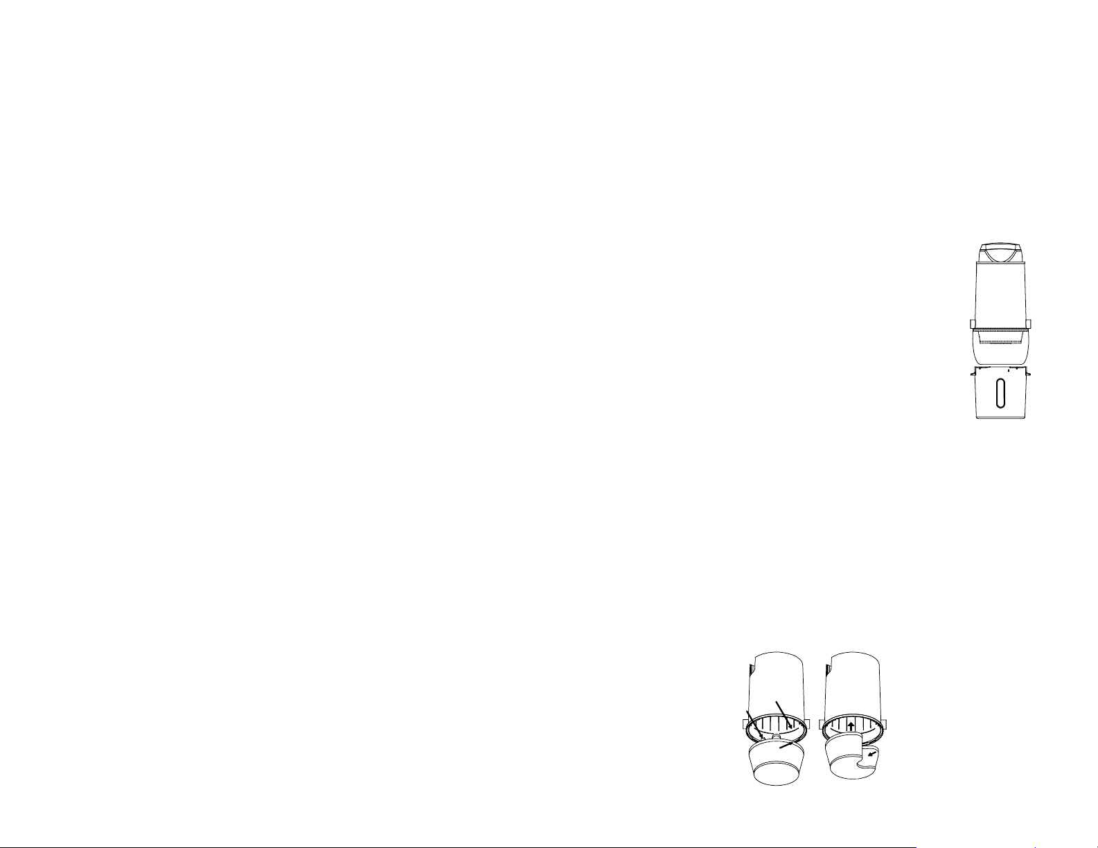
Replacement of the Cloth Filter Bag (ZCV782, ZCV783,
ZCV784)
NOTE: Removal of cloth filter is not advised and is not normally necessary
The band in rim of cloth filter must be secured into corresponding groove in intermediate body to ensure an airtight seal.
If for any reason, the cloth filter has been dislodged during shipment it must be
reinstalled prior to use.
Folding back filter band as show, align it with groove in body and uncoil. Final
portion of band should require a slight push to “POP” it into place. If not, remove and repeat installation procedure.
Use Finger Loop
for removal of filter
Filter Groove
Cloth Filter
Plastic Bag
Filter Band
7
Page 3

Cleaning Accessories
Optional accessories for the central vacuum cleaner are available through your local
dealership.
HOW TO MAINTAIN THE CENTRAL VACUUM CLEANER
The instructi ons given in this booklet serve as a guide to routine maintenance.
Proper airflow or suction can be maintained by k eeping the filters clean and the hose
and the plastic pipe free from clogs. Check the Trouble Shooting sect ion in this
booklet for suggestions before calling for service.
Empty the Dirt Bucket (ZCV782, ZCV783, ZCV784)
The ZCV782 is equippe d with a self-cleaning c loth filter. The dirt and debris is collected in the detachable dirt bucket. Model s which do not use a paper bag must
have the dirt removed from the dirt bucket. Rel ease the clamps or turn the buc ket to
the left. Remove and em pty the contents. Brush the filter while the bucket is off the
power unit. Return the bucket to the power unit and secure. Be sure the bucket is
securely attached to avoid any suction leakage.
Replace Paperbag Filter (ZCV781)
The ZCV781 is equipped with a paperbag filter. The paperbag filter
will collect the di rt and debris inside the ba g. The paperbag filter i s
located in the top end of the power unit. To remove the paperbag
filter, detac h the lid of the power unit by twisting it and removing i t.
The paperbag can be taken off and disposed of. A new filter paperbag is put in place and the lid securely attac hed again with a twist
movement. Be sure the paperbag and the lid are securely attached to
avoid any suction and dirt leakage.
Filter and Disposable Paper Bag
Reduced airflow or suction indicates the central vacuum cleaner is not
operating at maximum efficiency. If the disposable paper bag is ful l or a filter is
clogged, no air can pas s through the unit and no cl eaning will take place. Remove
and dispose of the paper bag.
Do not operate this unit without all filters in place.
Optional
DISPOSABLE PAPER FILTER BAG WITH CLOTH FILTER (cannot be used with dual intake/inta k e - utility installat ions)
NOTE: Disconnect power cord from electrical outlet before
cleaning the filter.
The elbow with the paper bag adapter must be installed, in
the body facing downward as shown for the paper bag.
1. Using pipe clamp, attach 90º sweep with bag adapter to
45º intake fitt ing as shown. Can only be used with si ngle intake installations.
2. Hold the bag collar with fingertips and align the bumps
on the adapter with the bump cutouts in the c ollar.
3. Insert adapter and pus h the bag collar all the way up to
the lip on the elbow.
IMPORTANT SAFEGUARDS
When using an electrical appliance, basic precautions should always be
followed, including the following:
READ ALL INSTRUCTIONS BEFORE USING THIS VACUUM CLEANER
DANGER - Always unplug power unit from the electrical outlet be-
fore servicing and cleaning.
WARNING - To reduce the risk of burns, fire, electric shock, or in-
jury to persons:
1. Keep cord away from heated surfaces.
2. Do not allow to be used as a toy. Close supervision is necessary
when this vacuum is used by or near children.
3. Use this vacuum only for its intended use as described in this manual. (Use of attachments not recommended by the manufacturer
may cause fire, electric shock, or injury.)
4. Never operate this vacuum if it has a damaged cord or plug, if it is
not working properly, if it has been dropped or damaged. Return to
service center or have service person examine and repair.
5. Do not pull or carry this power unit by supply cord, use cord as a
handle, close a door on cord, or pull cord around sharp edges or
corners.
6. Never disconnect plug by pulling on cord. To disconnect from outlet, grasp the plug, not the cord.
7. Do not put any object into openings. Do not use with any opening
blocked; keep free of dust, lint, hair, and anything that may reduce
air flow.
8. Keep hair, face, fingers, all body parts, and loose clothing away
from any openings (and revolving brush and nozzle).
9. Do not pick up cigarettes, live hot ashes, matches, or similar materials.
10. Never operate vacuum without dust bag and/or filter in place.
11. To disconnect, turn all controls to the OFF position; then remove
plug from outlet.
12. Never handle plug, cord, or power unit with wet hands.
13. Electric shock could occur if used on wet surfaces.
14. Use extra care when cleaning on stairs.
15. Do not use to pick up flammable or combustible liquids such as
gasoline, or use in areas where they may be present.
16. “Connect to a properly grounded outlet only. See grounding instruction.”
SAVE THESE INSTRUCTIONS
6
1
Page 4

Grounding Instructions
This appliance must be grounded. If it should malfunction or breakdown, grounding provides a path of least resistance for electric current
to reduce the risk of electric shock. This appliance is equipped with a
cord having an equipment-grounding conductor. The cord must be connected to an appropriate circuit that is properly installed and grounded
in accordance with all local codes and ordinances. (The Model ZCV781
is double insulated, therefore not applicable.)
WARNING
Improper connection of an equipment-grounding conductor can result in
risk of electric shock. Check with qualified electrician or service person
if you are in doubt as to whether the outlet is properly grounded. Do not
modify the plug provided with the appliance. If it will not fit the outlet,
have proper outlet installed by a qualified technician.
This appliance is for use on a nominal 230/240 V circuit and has a
grounded plug. Make sure that the applianc e is conn e c ted to an outlet
having the same configuration as the plug. No adapter should be used
with this appliance. Check power unit manual/automatic switch and all
inlet valves for operation. This appliance is intended for household use.
GENERAL INFORMATION
The central vacuum cleaner is designed for dry pick up of household
dirt and dust. Avoid picking up hard or sharp objects with the system to
prevent hose and plastic pipe damage or clogs. The instructions in this
booklet serve as a guide to routine maintenance.
Service Information
The instructions in this booklet serve as a guide to routine maintenance.
If additional service is required, please contact your nearest Electrolux
store or Electrolux Service Department.
DO NOT OIL
The motor is permanently lubricated and sealed. Do not oil the motor at
any time.
Rating Plate
The model, type and serial number are on the rating plate located on
the motor hood. For prompt and complete service information, always
refer to these numbers when inquiring about service.
Connect the two low voltage terminals, as shown in Figure A, to the power unit and to the
wires installed with the main trunk line. It is recommended you secure other connections
with wire nuts. Be certain you comply with your local electrical codes and regulations.
Plug the cord into a grounded receptacle as shown and into the power unit control module
as shown in figure B. You are now ready to check the installation of the unit.
WARNING: Electric shock could occur if used on wet surfaces.
WIRING: Check local codes but us e not less t han #14-2 with ground wire. Connect
power unit cord to appropriate electrical circuit. Be sure line voltage is sufficient to handle
10 amp load.
• Plug the hose into each inlet valve to be sure the electrical contacts operate properly.
• Check each inlet valve for air leaks.
• Check each pipe connection for air leaks.
• Be sure the paper bag and filters are properly installed in the power unit.
• Your cleaning system is ready to use.
HOW TO USE THE CENTRAL VACUUM CLEANER
The central vacuum cleaner is designed to provide the utmost in dust-free, quiet cleaning.
The power unit, which is mounted in a remote area of your hose, is connected to centrally
located inlet valves with a system of lightweight plastic pipes. Using the cleaner is as
simple as inserting the vacuum hose into an inlet valve after attaching the appropriate
tool.
General Operation
The central vacuum power unit is connected to a standard electrical outlet. The power
unit starts automatically when the vacuum hose is connected to an inlet valve in the
house. The power unit stops automatically, when the vacuum hose is pulled out of the
inlet valve.
When the vacuum hose is connected to an inlet valve, the metal ring on the hose-end
creates the electrical contact, and the power unit starts up. When the hose is removed
from the inlet valve, the power unit will stop again automatically.
If the hose used has a handle with an on-off switch, the operation of the power unit is controlled by that switch, after the hose has been connected to the inlet valve.
Overload-Protection Reset Button
The central vacuum cleaner features an overload protection (circuit breaker) which can be
reset should the motor be overloaded causing the circuit to open. Should this happen
and the power unit fails to operate, depress the reset button which is located on the side
of the power unit. If the protector continues to trip, contact the nearest Sears store of
Sears Service Department.
Inlet Valves
Each inlet valve has low voltage electrical contacts which allow activation of the power
unit motor when the hose is connected. The system shuts off as soon as the hose is removed. An obstruction in the inlet valve may cause the power unit to continue to run after
the hose is removed from the inlet. Check all the inlet valves and remove any obstruction
to shut down the power unit. When unplugging the hose from the inlet valve, hold the
inlet cover open for a few seconds to allow the suction to decrease and protect the inner
seal.
2
5
Page 5

Planning
If your home already has the system of plastic pipes and inlet valves, you are ready to
install the power unit (refer to Install Power Unit sections, below). If not, you can contract
to have the system installed by a professional or you may choose to do-it-yourself . If you
plan to install the system yourself, it is important to carefully plan the location of each inlet
valve, the power unit and the network of plastic pipes. This booklet only deals with the
installation of the power unit; “How-To” booklets are generally included with installat i on
kits to buy. The kits should contain enough plastic pipes and fittings and inlet valves for
your needs. The unit is supplied with a utility inlet either in the unit or separately. To install additional inlets be sure to use a 90 “Tee Wye” to install the separate utility inlet near
the cleaner.
Power Unit Location
NOTE:
and any adjacent wall and at least 70 cm from the
floor.
WARNING: Do not block the hood ventilation openings or duc ts.
Lack of ventilation airflow
The power unit should be located as far away from the general living area as possible, yet
accessible so you can remove the dirt bucket, paper bag, reach the filter and inspect the
power unit. A typical location would be in a garage where additional inlet valve could be
used to vacuum your car, your garage area or where emptying dirt and cleaning the filter
would be more convenient. Other suitable locations are in the basement, laundry room or
ventilated storage room. It is recommended that the exhaust be vented outside. Never
vent into a wall, a ceiling or a concealed space in the house.
Mount power unit at least 30 cm from the ceiling
Install Power Unit
You are now ready to install the power unit. Be sure the power unit will be located at
least 30 cm from the ceiling and any adjacent wall and at least 70 cm from the floor. The
motor hood ventilation should never be obstructed. The unit must be mounted within 1.8
meters of a grounded electrical plug. Be sure you will not overload the circuit. Check to
be sure you will be able to remove the bucket, paper bag, reach the filter and inspect the
power unit.
Compare the distance between the power unit mounting bracket and the wall stud in the
chosen mounting location. If the mounting bracket cannot be mounted on the stud, it is
suggested you use a length of board mounted horizontally to the studs. Drill mounting
holes to start screws.
Hang the power unit. Align the power unit intake fitting to the main trunk line projecting
from the wall and the exhaust port to the outdoor exhaust pipe. Secure each joint using
duct tape or electrical tape. DO NOT GLUE. Attach the exhaust pipe to the motor exhaust if exhausting outdoors. It is recommended that the exhaust be vented outside.
Never vent into a wall, a ceiling or a concealed space in the house.
Figure A Figure B
4
Specifications Model ZCV781 Model ZCV782 Model ZCV783 Model ZCV784
Dimensions HxW 592 x 414 mm 878 x 414 mm 954 x 414 mm 954 x 414 mm
Weight (boxed) 9 kg 10.5 kg 11.5 kg 13.5 kg
Electricity 230V 230V 230V 230V
Circuit Breaker 10A 10A 10A 10A
Insulation IP 24 IP 10 IP 10 IP 10
Motor 1-stage TF 135 mm 1-stage TF 135 mm 3-stage BP 145 mm 3- s tage BP 18 2 mm
Motor Effect 1200W 1200W 1500W 1550W
Max Water Lift 28 kPa 28 kPa 33 kPa 37 kPa
Max Air Flow 50 l/s 50 l/s 48 l/s 49 l/s
Max Airwatts 518 AW 518 AW 445 AW 560 AW
Noise Level 64 dB(A) 64 dB(A) 68 dB(A) 70 dB(A)
Filtration Paper bag Self cleaning Self cleaning Self cleaning
Disposable Paperbag Yes Optional Optional Optional
Self-cleaning Filter/Dirt Canister No Yes Yes Yes
Dirt Capacity - Dirt Bucket/Bag 31 liter 31 liter 31 liter 31 liter
3
 Loading...