

Page 1
LF 650
15
30
45
60
75
MAX
MAX
S
S
0
0
10
D
D
10
90
20
20
Instructions for use
GB
Please read and save these
instructions.
Gebrauchsanleitung
D
Bitte lesen und aufbewahren.
Instruction d’utilisation
F
Prière de lire et de conserver.
Istruzioni d’uso
I
Si prega di leggere le istruzioni e
di conservarle.
Instrucciones de uso
E
Lea y conserve estas
instrucciones por favor.
Instruções de serviço
P
Por favor leia e conserve em seu
poder.
Gebruiksaanwijzing
NL
Lees en let goed op deze
adviezen.
Brugsanvisning
DK
Vær venlight at læse og
opbevare.
Bruksanvisning
S
Var god läs och tag tillvara dessa
instruktioner.
Käyttöohje
FIN
Lue ja säilytö
Page 2

Introduction
Technical Data
Advice for your
safety
Measured sound
value
Measured
vibration value
Mains
connection
Use
ENGLISH
You demand the best and buy quality – quality provided by Atlas Copco.
We have built for you a reliable and lasting tool. Working effectively and without
endangering your health is only possible if these instructions for use are being read
carefully before first using this tool. We want to satisfy our customers and would like
you to buy again AEG Electric Power Tools from Atlas Copco.
Nominal power 650 W. . . . . . . . . . . . . . . . . . . . .
No-load speed 10000 min
Groove depth max. 19 mm. . . . . . . . . . . . . . . . . .
Groove width 4 mm. . . . . . . . . . . . . . . . . . . . . . . . .
Swivelling range 0–90
Router diameter 100 mm. . . . . . . . . . . . . . . . . . .
Blade bore diameter 22 mm. . . . . . . . . . . . . . . . . .
Spindle thread M 10. . . . . . . . . . . . . . . . . . . . .
Weight 2,8 kg. . . . . . . . . . . . . . . . . . . . . . . . . . . .
. . . . . . . . . . . . . . . . . . .
. . . . . . . . . . . . . . . . . .
-1
o
Please pay attention to the safety instructions in the attached leaflet!
Always use the protective shields on the machine.
Always wear goggles when using the machine. It is recommended to wear gloves,
sturdy non slipping shoes and apron.
Sawdust and splinters must not be removed while the machine is running.
Do not pierce the motor housing as this could damage the double insulation (use
adhesives).
Always disconnect the plug from the socket before carrying out any work on the
machine.
Only plug-in when machine is switched off.
Keep mains lead clear from working range of the machine. Always lead the cable
away behind you.
Only use professionally grinded router cutters.
If possible, clamp the workpiece down. Lead the machine with both hands.
Only use properly sharpened blades, otherwise increased cutting forces will shatter
the workpiece. Only use blades intended for manual tool advance.
Do not stop the blade by hand after switching off.
The base plate must not be clamped down while the blade is extended. Lowering
and raising the blade must be easy going.
Always fit the suction nozzle or the by–pass nozzle before using the joiner.
Dust that arises when working in wood or using the tool on industrial material can be
dangerous to health. In this case connect the tool to a suction device.
Typically the A-weighted noise levels of the tool are:
Sound pressure level = 87 dB (A).
Sound power level = 100 dB (A).
Wear ear protectors!
Typically the hand-arm vibration is below 2.5 m/s2.
Connect only to a single-phase AC current supply and only to the mains voltage
specified on the rating plate. Connection to sockets without earth protection is
possible as the appliance features protective insulation to DIN 57 740/ VDE 0740
and CEE 20. Radio suppression complies with the European standard EN 55014.
When fitting the plug, make sure that the brown (live) wire of this appliance is
connected to the plug terminal marked L or coloured red, and the blue (neutral) wire
of this appliance is connected to the plug terminal marked N or coloured black.
Under no circumstances must the wires of this appliance be connected to the earth
terminal of the plug marked either E, with the earth symbol or coloured green or
green/yellow.
The joiner can be used for mortise joints in solid wood, plywood, chipboard, fibre
board, plexiglass, and artificial marble.
Do not use this product in another way as stated for normal use.
2
LF 650
Page 3
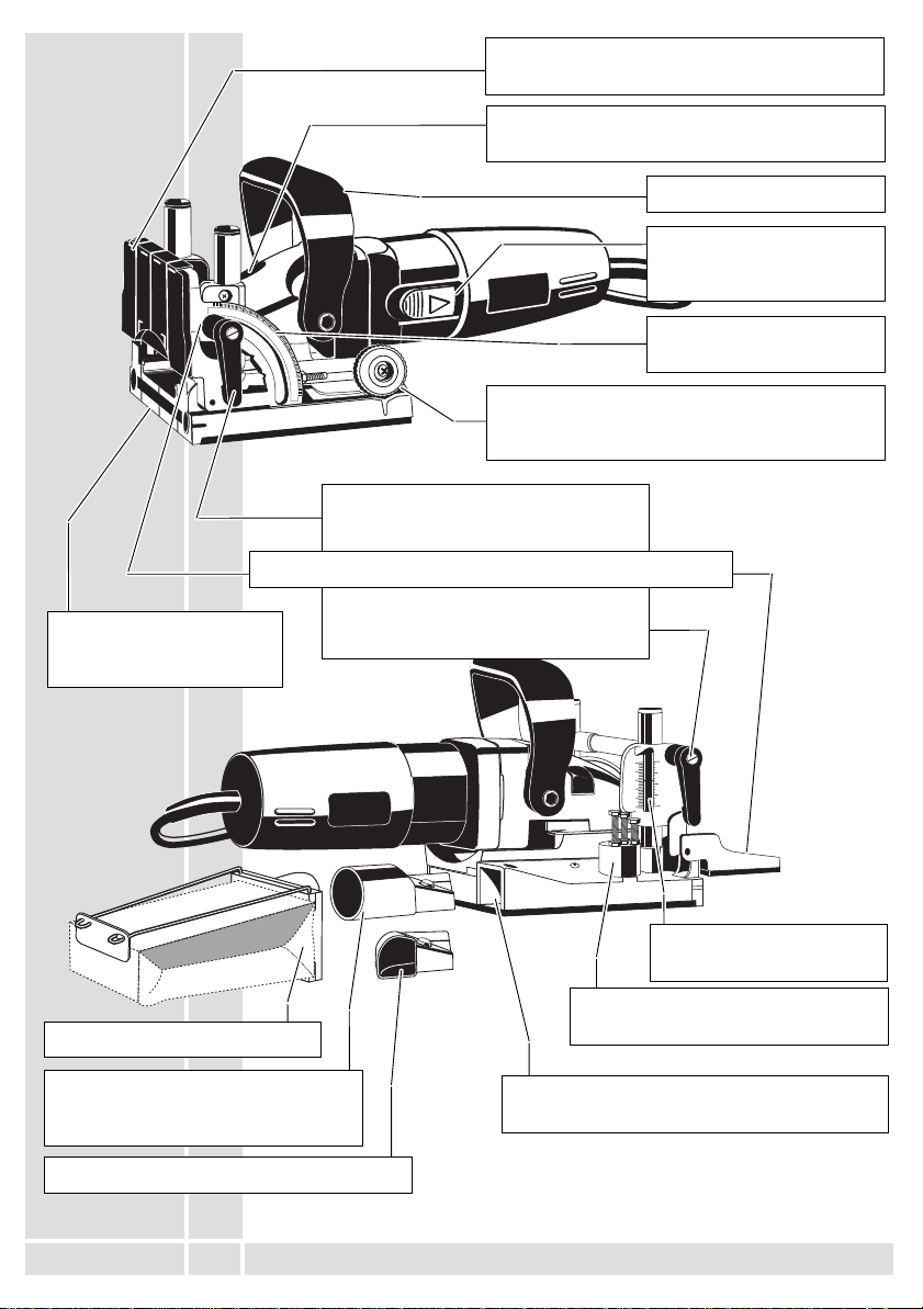
Brief description
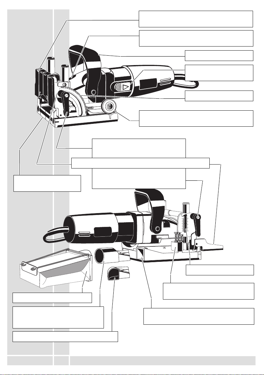
Base plate with markings
for easy cutting
Push–on plate to prevent unintentional touching
of the extended blade.
Spindle lock to lock working spindle for
exchanging router cutters.
Auxiliary handle
On–/Off switch built as a
large slide.
15
30
45
60
75
90
MAX
MAX
S
S
0
0
10
D
D
10
20
20
Cutting depth adjustment knob to adjust the
Scale for the fence angle
cutting depth to the various biscuit dowel sizes.
After unlocking the left clamping lever
the swivel fence can be adjusted
infinitely variable.
Swivel fence with height adjustment
After unlocking the right clamping lever
the height of the swivel fence can be
adjusted infinitely variable.
AEG CleanLine System
Suction nozzle to connect the AEG
CleanLine System or a suction hose
(accessory)
By–pass nozzle
ENGLISH
3
0
0
10
1
/
2
20
1
Scale for height adjustment
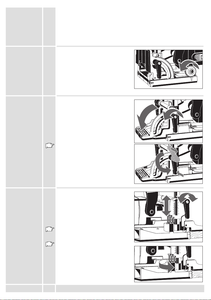
Depth guide to pre–set three different
board thicknesses
Sawdust ejector, can be connected with a
suction nozzle or a by–pass nozzle
Modifications: Text, diagrams and data are correct at the time of
printing. In the interest of continuous improvement of our
products, technical specifications are subject to alteration without
prior notice.
LF 650
Page 4
Choosing the
10
sizes of the
biscuit dowels
The size of the biscuit dowels to be used depends on the thickness of the material.
Always use biscuit dowels of the biggest possible size to ensure a solid joint. If the
working material is thicker than 25 mm, use 2 biscuit dowels on top of each other.
Thickness of Material Size of Biscuit Dowel Measures
8–12 mm 0 47x15x4
12–15 mm 10 53x19x4
> 15 mm 20 56x23x4
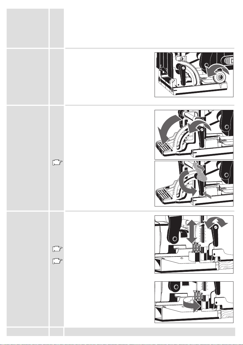
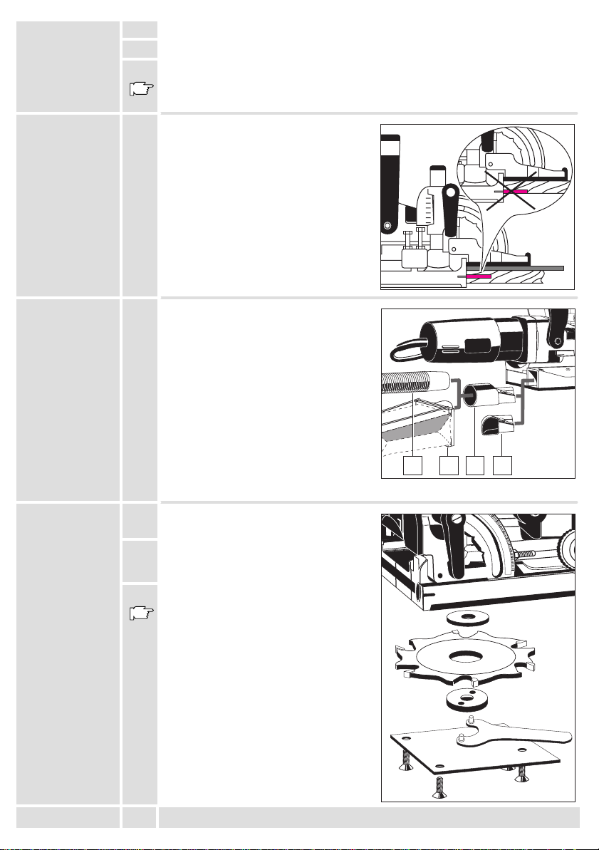
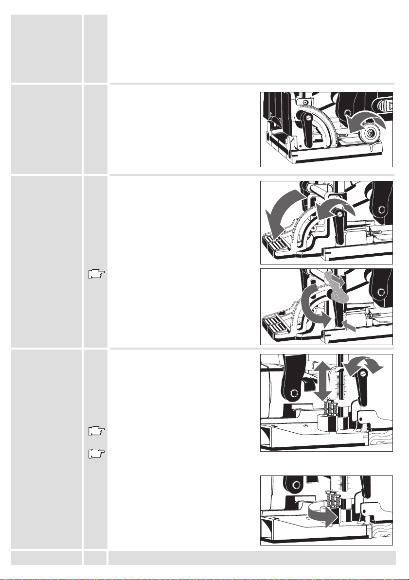
Setting of routing
depth
Setting the
cutting angle
Setting the
machine to the
thickness of the
board
Set the cutting depth with the adjustment
knob according to the chosen biscuit dowel
to be used.
Size Biscuit Dowel Cutting Depth
No.0 0 8.0 mm
No.10 10 10.0 mm
No.20 20 12.3 mm
Simplex S 13.0 mm
Duplex D 14.7 mm
maximum Max 19.0 mm
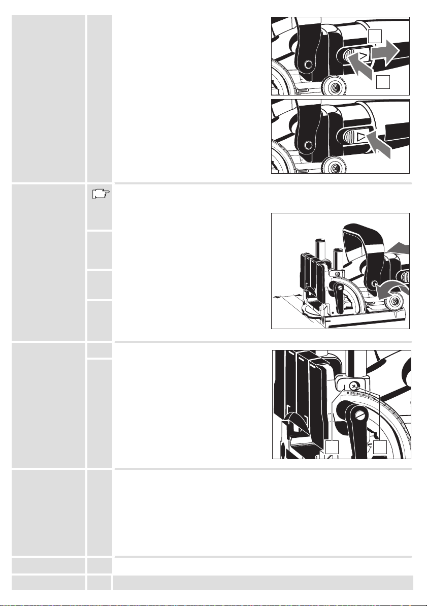
Unlock the left clamping lever, set the
swivel fence with aid of the scale to the
required angle (e.g. for mitre joints), and
re–fasten the clamping lever.
The angles most frequently used (22.5
o
, 67.5o) can be quickly adjusted with
45
o
,
aid of notched stages.
Should the locked clamping lever be in the
way when working with the tool, fasten it in
a different position by pulling it out without
unlocking it.
To be able to cut the groove for the biscuit
dowel centrically, the joiner must be pre–set
to the board thickness. Unlock the right
clamping lever, set the swivel fence with aid
of the scale to the required board thickness,
and re–fasten the clamping lever.
The values on the scale are only applicable
when the push–on plate is fitted.
Should the locked clamping lever be in the
way when working with the tool, fasten it in
a different position by pulling it out without
unlocking it.
Three board thicknesses can be pre–set at
the depth guide. It is factory pre–set to 16,
19, and 25 mm.
15
30
45
60
75
90
90
75
60
45
30
15
0
90
75
60
45
30
15
0
0
10
20
20
MAX
MAX
S
S
0
0
10
D
D
10
20
20
0
1
/
2
1
1
/
2
1
ENGLISH
4
LF 650
Page 5
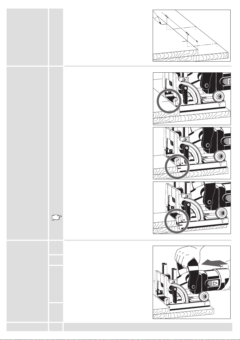
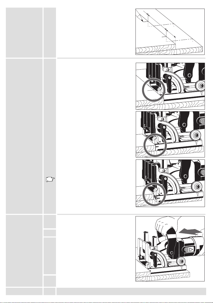
Marking the
groove
distances
Place the two boards to be joined on top of
each other (flush), fix them with
screw–clamps and mark the center of the
grooves. The distance between the grooves
should be 10–15 cm. Smaller workpieces
do not have to be marked.
Depending on the width of the boards the
machine can be positioned in different
ways.
Wide boards:
Position the machine to the workpiece such
that the base plate middle marking is facing
the board marking.
Narrow boards:
Position the machine with the outer edge of
the base plate to the edge of the workpiece.
10-15 cm
15
15
4-6 cm
30
45
30
45
60
75
90
60
75
90
MAX
MAX
S
S
0
0
10
D
D
10
20
20
MAX
MAX
S
S
0
0
10
D
D
10
20
20
Cutting grooves
ENGLISH
Very narrow boards:
Position the machine with the outer marking
of the base plate to the edge of the
workpiece.
This setting can also be used for the case
that the biscuit joint is located close to the
edge.
1. Position the machine as described above.
2. Switch the machine on.
3. Push the machine forward and plunge the
blade slowly into the material as far as it will
go. Hold the machine with both hands.
Slightly release the pressure, the motor part
is pulled back to the original position by
resilience.
4. Switch the machine off.
5
15
30
45
60
75
90
15
30
45
60
75
90
MAX
MAX
0
0
10
10
20
20
MAX
MAX
S
S
0
0
10
D
D
10
20
20
S
S
D
D
LF 650
Page 6
Joining of
X
X
workpieces
1. Apply glue to the grooves.
2. Insert a biscuit dowel.
3. Put together the workpieces and fix them with clamps, tightening straps, or similar.
The biscuit dowels well up due to the wetness of the glue, and the joint is additionally
strengthened.
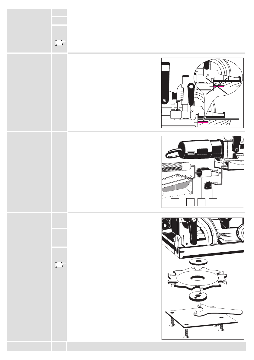
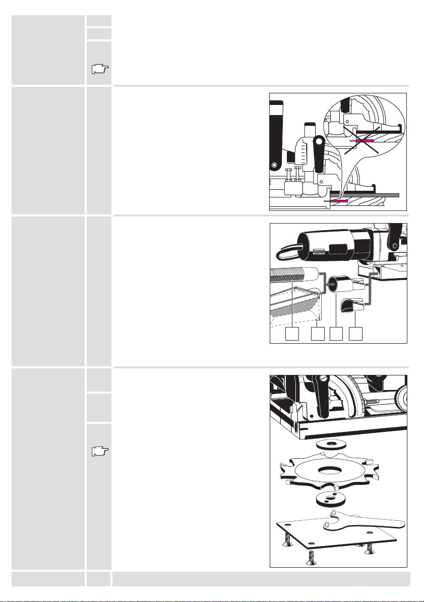
Cutting grooves
in thin boards
Sawdust ejector
Exchanging the
blades
When cutting thin boards (thickness of
material less than 16 mm) a thin piece of
wood must be placed under the swivel
fence, otherwise the groove is cut too close
to the surface of the board.
The following devices can be connected to
the sawdust ejector:
suction hose
(via suction nozzle )
AEG CleanLine System
(via suction nozzle )
suction nozzle
by–pass nozzle
We recommend the AEG NTE 1100
electronic wet–and–dry vacuum cleaner,
which has a socket to which this machine
can be connected directly. As soon as the
saw is switched on, the wet–and–dry
vacuum cleaner switches itself on
automatically.
1. Loosen the four screws and remove the
cover plate.
2. Depress the spindle lock and remove the
flange with aid of a pin–type face spanner.
Remove the blade.
3. To insert a blade proceed in reverse order.
When inserting the blade, take care that the
arrows on the blade and on the base plate
conform.
31
2 4
45
60
0
75
90
0
10
10
ENGLISH
6
LF 650
Page 7
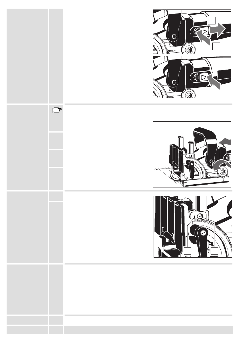
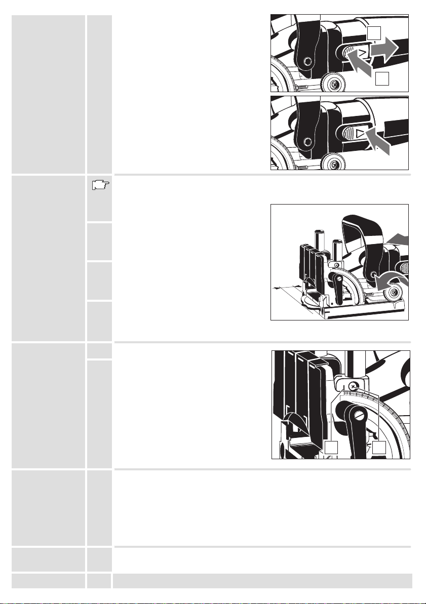
On-/off switch
3
0
0
3
Switching on:
Slide back the On/Off switch. To lock,
depress the front part of the sliding switch.
Switching off:
To unlock, depress the back part of the
sliding switch. The switch will automatically
move back to ”0”.
1
0
45
60
75
0
45
60
75
MAX
MAX
S
S
0
0
1
D
D
1
MAX
MAX
S
S
0
0
2
Adjusting the
cutting depth
Adjusting the
angle setting
Maintenance
After exchanging the blades the cutting depth should be checked and adjusted, if
necessary.
1. Set the cutting depth adjusting knob to the
Max position.
2. Push the motor part forward as far as it will
go and turn the blade until one tooth has
reached the front position.
3. Measure the distance from the edge of the
base plate to the cutting tooth; it must be 19
mm in the Max position.
4. In order to correct the cutting depth, loosen
the counter nut and turn the set screw as
required. (1 rotation = 0.7 mm) Re–tighten
the counter nut.
1. Set the swivel fence to 0
o
.
19 mm
15
30
45
60
75
90
2. Loosen the screw and move the
marking until it faces the 0-setting of the
swivel fence. Re-tighten the screw.
15
1
The ventilation slots of the machine must be kept clear at all times.
Use only AEG accessories and spare parts. Should components need to be
replaced which have not been described, please contact one of our AEG service
agents (see our list of guarantee/service addresses).
If needed, an exploded view of the tool can be ordered. Please state the ten–digit
No. as well as the machine type printed on the label and order the drawing at your
local service agents or directly at: Atlas Copco Electric Tools GmbH, Postfach 320,
D–71361 Winnenden.
MAX
MAX
S
S
0
0
10
D
D
10
20
20
30
45
60
75
2
Accessories
ENGLISH
The range of accessories with part numbers is shown in our catalogue.
7
LF 650
Page 8

Vorwort
Technische
Daten
Hinweise für
Ihre Sicherheit
Geräusch-
meßwerte
Vibrations-
meßwerte
Netzanschluß
Verwendung
DEUTSCH
Sie sind anspruchsvoll und kaufen Qualität – Qualität von Atlas Copco.
Wir haben für Sie ein haltbares und möglichst sicheres Elektrowerkzeug gebaut.
Effektives und weitgehend gefahrloses Arbeiten ist aber nur möglich, wenn Sie diese
Gebrauchsanleitung lesen und danach handeln. Wir wollen, daß Sie sich auch in
Zukunft entscheiden für AEG-Elektrowerkzeuge von Atlas Copco
Nennaufnahme 650 W. . . . . . . . . . . . . . . . . . . .
Leerlaufdrehzahl 10000 min
. . . . . . . . . . . . . . . . .
-1
Nuttiefe max 19 mm. . . . . . . . . . . . . . . . . . . . . . .
Nutbreite 4 mm. . . . . . . . . . . . . . . . . . . . . . . . . . . .
Schwenkbereich 0–90
. . . . . . . . . . . . . . . . .
o
Fräser-ø 100 mm. . . . . . . . . . . . . . . . . . . . . . . . . .
Aufnahme–ø 22 mm. . . . . . . . . . . . . . . . . . . . . . .
Spindelgewinde M 10. . . . . . . . . . . . . . . . . . .
Gewicht 2,8 kg. . . . . . . . . . . . . . . . . . . . . . . . . . .
Sicherheitshinweise auf Beiblatt (4000 3330 24) beachten!
Schutzeinrichtung der Maschine unbedingt verwenden.
Beim Arbeiten mit der Maschine stets Schutzbrille tragen. Schutzhandschuhe, festes
und rutschsicheres Schuhwerk und Schürze werden empfohlen.
Späne oder Splitter dürfen bei laufender Maschine nicht entfernt werden.
Gehäuse der Maschine nicht anbohren, da sonst die Schutzisolierung unterbrochen
wird (Klebeschilder verwenden).
Vor allen Arbeiten an der Maschine Stecker aus der Steckdose ziehen.
Maschine nur ausgeschaltet an die Steckdose anschließen.
Anschlußkabel stets vom Wirkungsbereich der Maschine fernhalten. Kabel immer
nach hinten von der Maschine wegführen.
Nur fachmännisch geschliffene Fräser verwenden.
Werkstücke wenn möglich festspannen und Maschine mit beiden Händen führen.
Nur einwandfrei geschärfte Fräser verwenden, da sonst erhöhte Schnittkräfte das
Werkstück zerschlagen. Nur Fräser für Handvorschub verwenden.
Den Fräser nach dem Ausschalten nicht abbremsen.
Die Grundplatte darf bei ausgefahrenem Fräser nicht festgeklemmt werden. Das
Aus– und Einfahren des Fräsers aus der Grundplatte muß leichtgängig funktionieren.
Nur mit aufgestecktem Umlenkstutzen oder Absaugstutzen arbeiten.
Bei längerem Bearbeiten von Holz oder bei gewerblichem Einsatz für Materialien, bei
denen gesundheitsgefährdende Stäube entstehen, ist das Elektrowerkzeug an eine
geeignete Absaugvorrichtung anzuschließen. (In Deutschland werden für Holzstäube
aufgrund TRGS 553 geprüfte Absaugeinrichtungen gefordert).
Für andere Materialien muß der gewerbliche Betreiber die speziellen Anforderungen
mit der zuständigen Berufsgenossenschaft klären.
Der A-bewertete Geräuschpegel des Gerätes beträgt typischerweise:
Schalldruckpegel = 87 dB (A).
Schalleistungspegel = 100 dB (A).
Gehörschutz tragen!
Die Hand-Arm Vibration ist typischerweise niedriger als 2,5 m/s2.
Nur an Einphasen-Wechselstrom und nur an die auf dem Leistungsschild
angegebene Netzspannung anschließen. Anschluß ist auch an Steckdosen ohne
Schutzkontakt möglich, da eine Schutzisolierung nach DIN 57 740/ VDE 0740 bzw.
CEE 20 vorliegt. Die Funkentstörung entspricht der Europanorm EN 55014.
Die Flachdübelfräse eignet sich zum Fräsen von Nuten für Flachdübelverbindungen
in Massivholz, Sperrholz, Spanplatten, Faserplatten, Plexiglas und Kunstmarmor.
Dieses Gerät darf nur wie angegeben bestimmungsgemäß verwendet werden.
8
LF 650
Page 9
Kurzbeschreibung
Grundplatte mit
Markierungen zum Fräsen
nach Anriß.
Aufsteckplatte zum Schutz vor unbeabsichtigtem
Berühren des ausgefahrenen Fräsers.
Spindelarretierung zum Feststellen der
Arbeitsspindel beim Fräserwechsel.
Zusatzhandgriff
Ein-/Ausschalter als
großflächig geformter
Schiebeschalter ausgebildet.
15
30
45
60
75
90
MAX
MAX
S
S
0
0
10
D
D
10
20
20
Frästiefeneinstellrad zur Anpassung der
Skala Ablesen des
Anschlagwinkels
Frästiefe an die verschiedenen
Flachdübelgrößen.
Nach Lösen des linken Klemmhebels ist
der Schwenkanschlag stufenlos von
o
0–90
schwenkbar.
Höhenverstellbarer Schwenkanschlag
Nach Lösen des rechten Klemmhebels
ist der Schwenkanschlag stufenlos in
der Höhe verstellbar.
AEG CleanLine System
Absaugstutzen zum Anschluß des
AEG CleanLine Sytems oder eines
Absaugschlauches (Zubehör).
Umlenkstutzen
DEUTSCH
9
0
0
10
1
/
2
20
1
Skala zum Ablesen der
Höhenverstellung.
Revolvertiefenanschlag zur
Voreinstellung von drei Plattenstärken.
Späneauswurf zum Anschluß eines
Absaugstutzens oder eines Umlenkstutzens.
Änderungen: Text, Bild und Daten entsprechen dem technischen
Stand zur Zeit des Drucktermins. Änderungen im Sinne der
Weiterentwicklung unserer Produkte sind vorbehalten.
LF 650
Page 10
Wahl der
10
Dübelgrößen
Die Größe der Flachdübel ist von der Materialdicke abhänging.
Für eine solide Verbindung immer die größtmöglichen Flachdübel verwenden. Bei
Materialdicken über 25 mm 2 Flachdübel übereinander verwenden.
Materialdicke Dübelgröße Abmessung
8–12 mm 0 47x15x4 mm
12–15 mm 10 53x19x4 mm
> 15 mm 20 56x23x4 mm
Frästiefe
einstellen
Fräswinkel
einstellen
Maschine auf
Plattendicke
einstellen
Die Frästiefe am Einstellrad entsprechend
dem gewählten Flachdübel einstellen.
Größe Dübel Frästiefe
Nr.0 0 8,0 mm
Nr.10 10 10,0 mm
Nr.20 20 12,3 mm
15
30
45
60
75
90
MAX
MAX
S
S
0
0
10
D
D
10
20
20
Simplex S 13,0 mm
Duplex D 14,7 mm
maximal Max 19,0 mm
Linken Klemmhebel lösen,
Schwenkanschlag nach Skala auf
gewünschten Winkel einstellen (z.B. für
Gehrungsverbindungen) und Klemmhebel
wieder festdrehen.
Die Hauptwinkel 22,5
o
, 45o, 67,5o sind
über eine Kugelrastung schnelljustierbar.
30
15
0
90
75
60
45
Sollte der festgezogene Klemmhebel beim
Arbeiten stören, so kann er durch
Herausziehen in eine andere Position
gebracht werden ohne die Klemmung zu
lösen.
30
15
0
90
75
60
45
Um die Nut für den Flachdübel mittig
fräsen zu können, muß die
Flachdübelfräse auf die Plattendicke
eingestellt werden.
Hierzu rechten Klemmhebel lösen,
Schwenkanschlag nach Skala auf
0
0
10
1
/
2
20
1
entsprechende Plattendicke einstellen und
Klemmhebel wieder festziehen.
Die Skalenwerte gelten nur bei
angebrachter Aufsteckplatte.
Sollte der festgezogene Klemmhebel beim
Arbeiten stören, so kann er durch
Herausziehen in eine andere Position
gebracht werden ohne die Klemmung zu
lösen.
1
/
2
20
1
Am Revolveranschlag können drei
Plattendicken voreingestellt werden.
Werkseitig sind die Plattendicken 16, 19
und 25 mm eingestellt.
DEUTSCH
10
LF 650
Page 11
Nutenabstände
D
S
anreißen
Die zu verbindenden Platten seitlich
bündig aufeinander legen, mit
Schraubzwingen fixieren und die Mitte der
Nuten anreißen. Der Nutenabstand sollte
zwischen 10–15 cm betragen.
Schmale Werkstücke brauchen nicht
angerissen werden.
Je nach Breite der Platten kann die
Maschine unterschiedlich positioniert
werden.
Breite Platten:
Maschine mit der Mittelmarkierung der
Grundplatte am Anriß positionieren.
10-15 cm
4-6 cm
15
30
45
60
75
90
MAX
MAX
S
0
0
10
D
10
20
20
Nuten fräsen
Schmale Platten:
Maschine mit der Außenkante der
Grundplatte positionieren
Sehr schmale Platten:
Maschine mit der Außenmarkierung der
Grundplatte positionieren.
Diese Einstellung kann auch verwendet
werden, wenn die Flachdübelverbindung
nahe am Rand sitzen soll.
1. Maschine wie zuvor beschrieben
positionieren.
2. Maschine einschalten.
3. Maschine am Motorteil nach vorn schieben
und mit dem Fräser langsam in das
Material bis zum Anschlag eintauchen.
Dabei die Maschine mit beiden Händen
halten.
Druck etwas nachlassen; das Motorteil
wird durch Federkraft in die
Ausgangsposition zurückgezogen.
4. Maschine wieder ausschalten
15
30
45
60
75
90
15
30
45
60
75
90
15
30
45
60
75
90
MAX
0
0
10
10
20
20
MAX
MAX
S
S
0
0
10
D
D
10
20
20
MAX
MAX
S
S
0
0
10
D
D
10
20
20
MAX
S
S
D
D
DEUTSCH
11
LF 650
Page 12
Werkstücke
X
X
verbinden
1. Die Nuten mit Leim versehen.
2. Flachdübel einsetzen.
3. Werkstücke zusammensetzen und mit geigneten Spannmitteln (Schraubzwingen,
Spannbänder o.ä.) spannen.
Durch die Feuchtigkeit des Leims quellen die Flachdübel auf und die Verbindung
erhält so zuätzliche Festigkeit.
Nuten fräsen in
dünnen Platten
Spanauswurf
Fräser wechseln
Beim Fräsen von dünnem Platten
(Materialstärke unter 16 mm) muß ein
dünnes Holz unter die Grundplatte gelegt
werden, sonst wird die Nut zu dicht an der
Oberfläche der Platten gefräst.
Am Spanauswurf können wahlweise
angeschlossen werden:
Saugschlauch
(über Absaugstutzen )
AEG CleanLine System
(über Absaugstutzen )
Absaugstutzen
Umlenkstutzen
Empfohlen wird der AEG Electronic–Naß–
und Trockensauger NTE 1100. Er erlaubt
das Anschließen der Maschine direkt an
die Steckdose des Naß–Trockensaugers.
Beim Einschalten der Maschine läuft der
Naß–Trockensauger automatisch an.
1. Die vier Schrauben lösen und
Abdeckplatte abnehmen.
2. Spindelarretierung drücken und
Spannflansch mit Zweilochmutterschlüssel
abschrauben. Fräser abnehmen.
3. Der Einbau des Fräser erfolgt in
umgekehrter Reihenfolge.
Beim Einbau des Fräsers darauf achten,
daß die Drehrichtungspfeile auf Fräser und
Grundplatte ubereinstimmen.
31
2 4
45
60
0
75
90
0
10
10
DEUTSCH
12
LF 650
Page 13
Ein-/Ausschalten
3
0
0
3
Einschalten:
Schiebeschalter nach hinten drücken und
zum Arretieren im vorderen Bereich nach
unten drücken
Ausschalten:
Schiebeschalter im hinteren Bereich nach
unten drücken, Schalter geht automatisch
in 0-Stellung zurück.
1
0
45
60
75
0
45
60
75
MAX
MAX
S
S
0
0
1
D
D
1
MAX
MAX
S
S
0
0
2
Frästiefe
justieren
Winkeleinstellung
justieren
Wartung
Nach einem Fräserwechsel sollte die Frästiefe kontrolliert und ggf. nachreguliert
werden.
1. Frästiefeneinstellrad auf Stellung Max
stellen.
2. Motorteil bis zum Anschlag nach vorn
schieben und Fräser verdrehen bis ein
Schneidzahn den vordersten Punkt
erreicht hat.
3. Abstand von Grundplattenkante bis
Schneidzahn messen; das Maß muß in
Stellung Max 19 mm betragen.
4. Um die Frästiefe ggf. zu korrigieren
19 mm
15
30
45
60
75
90
Kontermutter lösen und Gewindestift
entsprechend verdrehen (1 Umdrehung =
0,7 mm). Kontermutter wieder festziehen.
1. Schwenkanschlag in Stellung 0
o
stellen.
2. Schraube lösen und Markierung
verschieben, bis sie der 0–Marke des
Schwenkanschlags gegenübersteht.
Schraube wieder festziehen.
15
1
Stets die Lüftungsschlitze der Maschine sauber halten.
Nur AEG Zubehör und Ersatzteile verwenden. Bauteile, deren Austausch nicht
beschrieben wurde, bei einer AEG Kundendienststelle auswechseln lassen
(Broschüre Garantie/Kundendienstadressen beachten).
Bei Bedarf kann eine Explosionszeichnung des Gerätes unter Angabe der
Maschinen Type und der zehnstelligen Nummer auf dem Leistungsschild bei Ihrer
Kundendienststelle oder direkt bei Atlas Copco Electric Tools GmbH, Postfach 320,
D–71361 Winnenden angefordert werden.
MAX
MAX
S
S
0
0
10
D
D
10
20
20
30
45
60
75
2
Zubehör
DEUTSCH
Das Zubehör mit Bestellnummern ersehen Sie bitte aus unseren Katalogen.
13
LF 650
Page 14

Introduction
Caractéristiques
techniques
Conseils de
sécurité
Vous exigez ce qu’il y a de meilleur et vous achetez de la qualité – la qualité offerte
par Atlas Copco. Vous vous êtes dotés d’un outil de qualité durable. Ce n’est qu’en
lisant attentivement ces instructions avant d’utiliser l’outil que vous assurerez un
travail efficace et sans risque. Nous tenons à satisfaire notre clientèle et nous
espérons que vous achèterez encore des
outils électriques AEG d’Atlas Copco.
Puissance absorbée 650 W. . . . . . . . . . . . . . . .
Régime à vide 10000 min
Profondeur de rainure max 19 mm. . . . . . . . . . . .
Largeur de rainure 4 mm. . . . . . . . . . . . . . . . . . . .
Plage de basculement de la butée orien table0–90
Diamètre des fraises 100 mm. . . . . . . . . . . . . . . .
Diamètre de l’alésage intérieur 22 mm. . . . . . . . .
Filetage de la broche M 10. . . . . . . . . . . . . . .
Poids 2,8 kg. . . . . . . . . . . . . . . . . . . . . . . . . . . . .
. . . . . . . . . . . . . . . . . . .
-1
o
Respecter les instructions de sécurité se trouvant dans le prospectus ci-joint.
Il est absolument impératif d’utiliser le dispositif protecteur de la machine.
Toujours porter des lunettes protectrices lorsqu’on travaille avec la machine. Des
gants de sécurité et un masque de protection sont recommandés.
Ne jamais enlever les copeaux ni les éclats lorsque la machine est en marche.
Ne pas percer le carter de la machine; ceci pourrait entraîner une détérioration de
l’isolation de protection (utiliser des autocollants).
Avant tous travaux sur la machine extraire la fiche de la prise de courant.
Ne raccorder la machine au réseau que si l’interrupteur est en position arrêt.
Le câble d’alimentation doit toujours se trouver en dehors du champ d’action de la
machine. Toujours maintenir le câble d’alimentation à l’arrière de la machine.
N’utiliser que des fraises rectifiées par des professionnels.
Si possible serrer les pièces à travailler et guider la machine avec les deux mains.
N’utiliser que des fraises correctement affûtées, sinon la pièce risque d’être brisée
par les forces de coupe supérieures. N’utiliser que des fraises pour avance
manuelle.
Ne jamais tenter de ralentir la fraise encore en rotation après avoir éteint la machine.
La plaque de base ne doit pas être serrée lorsque la fraise se trouve en position
avancée. La fraise doit pouvoir sortir et entrer facilement dans la plaque de base.
Ne travailler qu’avec la tubulure d’aspiration ou la tubulure angulaire montée.
Mesure de bruit
Valeur de
vibration
mesurée
Branchement
secteur
Utilisation
FRANÇAIS
Lors de travaux de ponçage de longue durée, bois ou autres matériaux dégageant
des poussières nocives pour la santé, la machine est à raccorder à un appareil
d’aspiration.
Les mesures réelles (A) des niveaux de bruit de la machine sont:
Intensité de bruit = 87 dB (A).
Niveau de bruit = 100 dB (A).
Toujours porter des casques protecteurs!
La vibration de l’avant–bras est en–dessous de 2,5 m/s2.
Nos machines fonctionnent uniquement sur courant alternatif monophasé. S’assurer
que la tension du réseau correspond effectivement à celle indiquée sur la plaque
signalétique de la machine. Le branchement sur une prise de courant sans mise à
terre est possible du fait de la double isolation selon normes DIN 57 740/VDE 0740
et CEE 20. Antiparasitage selon normes européennes EN 55014.
L’entailleuse – rainureuse est appropriée au fraisage des rainures pour raccords à
biscuits dans bois massif, contre–plaqués, panneaux de particules, panneaux fibres,
plexiglas et marbre artificiel.
Comme déjà indiqué, cette machine n’est conçue que pour une utilisation normale.
14
LF 650
Page 15

Description
Plaque de base avec
repères pour fraisage
d’après traçage.
Plaque à emboîter pour éviter tout contact
imprévu avec la fraise en position avancée.
Blocage de la broche pour bloquer
l’arbre–moteur lors du changement de la fraise.
Poignée complémentaire
Interrupteur Marche/Arrêt
conçu comme interrupteur à
coulisse largement
15
30
45
60
75
90
MAX
MAX
S
S
0
0
10
D
D
10
20
20
Molette de réglage de la profondeur de
dimensionné.
Graduation pour l’indication
de l’angle de la butée.
fraisage pour l’adaptation de la profondeur de
fraisage aux différentes tailles des biscuits.
Après avoir lâché le levier de blocage
de gauche, la butée orientable peut être
basculée sans à–coups de 0 à 90°.
Butée orientable à réglage en hauteur
Après avoir lâché le levier de blocage
de droite, la butée orientable peut être
réglée en hauteur sans à–coups.
Système AEG Clean Line
Tubulure d’aspiration pour raccord du
système AEG Clean Line ou d’un
tuyau flexible d’aspiration
(accessoires).
Tubulure angulaire
FRANÇAIS
15
0
0
10
1
/
2
20
1
Graduation pour l’indication
du réglage en hauteur.
Butée de profondeur revolver pour
pré–réglage de trois épaisseurs de
planche.
Ejection de copeaux pour raccord d’une
tubulure d’aspiration ou d’une tubulure
angulaire.
Modifications: Les textes, les illustrations et les données
techniques correspondent à la situation au moment de
l’impression. Toutes modifications techniques sont réservées
dans le cadre du développement technique permanent.
LF 650
Page 16
Choix de la taille
10
du biscuit
La taille du biscuit dépend de l’épaisseur du matériau.
Afin d’obtenir un raccord solide, utiliser toujours les biscuits les plus grands
possibles. Pour des épaisseurs de matériau supérieures à 25 mm, utiliser 2 biscuits
en les posant l’un sur l’autre.
Epaisseur du matériauTaille du biscuitDimension
8–12 mm 0 47x15x4
12–15 mm 10 53x19x4
> 15 mm 20 56x23x4
Réglage de la
profondeur
de fraisage
Réglage de
l’angle de
fraisage
Réglage de la
machine
conformément à
l’épaisseur de la
planche
FRANÇAIS
Par l’intermédiaire de la molette régler la
profondeur de fraisage conformément au
biscuit choisi.
Taille BiscuitProfondeur de fraisage
N°0 0 8,0 mm
N°10 10 10,0 mm
N°20 20 12,3 mm
15
30
45
60
75
90
MAX
MAX
S
S
0
0
10
D
D
10
20
20
Simplex S 13,0 mm
Duplex D 14,7 mm
Maximale Max 19,0 mm
Lâcher le levier de blocage de gauche,
régler la butée orientable à l’aide de la
graduation afin d’obtenir l’angle souhaité
(par exemple pour des raccord en onglet),
puis resserrer le levier de blocage.
Les angles principaux 22,5°; 45° et 67,5°
peuvent être ajustés rapidement grâce à un
loqueteau à billes.
30
15
0
90
75
60
45
Au cas uù le levier de serrage gênerait le
maniement de la machine lors du travail, il
est possible de le retirer afin de le
posotionner différement sans pour autant
lâcher le serrage.
30
15
0
90
75
60
45
Afin de pouvoir fraiser au centre la rainure
pour le biscuit, il faut régler l’entailleuse –
rainureuse selon l’épaisseur de la planche.
Pour cela, lâcher le levier de blocage de
droite, régler la butée orientable à l’aide de
la graduation conformément à l’épaisseur
0
0
10
1
/
2
20
1
de la planche, puis resserrer le levier de
blocage.
Les valeurs de la graduation ne sont
valables que si la plaque à emboîter est
bien montée.
Au cas uù le levier de serrage gênerait le
maniement de la machine lors du travail, il
est possible de le retirer afin de le
1
/
2
20
1
posotionner différement sans pour autant
lâcher le serrage.
La butée revolver permet le pré–réglage de
trois épaisseurs de planche. Les valeurs
suivantes sont pré–réglées à l’usine: 16, 19
et 25 mm.
16
LF 650
Page 17

Traçage des
distances des
rainures
Poser les planches à raccorder de manière
à ce qu’aucune des planches ne déborde,
les fixer à l’aide des serre–joints à serrage
par vis et tracer le milieu des rainures. La
distance entre les rainures devrait être de
10 à 15 cm. Des pièces très étroites ne
doivent pas être tracées préalablement.
La machine peut être positionnée en
fonction des différentes largeurs des
planches.
Planches larges:
Positionner la machine de sorte que le
marquage au milieu de la plaque de base
se trouve au–dessus du traçage.
Planches étroites:
Positionner la machine avec le bord
extérieur de la plaque de base.
10-15 cm
15
15
4-6 cm
30
45
30
45
60
75
90
60
75
90
MAX
MAX
S
S
0
0
10
D
D
10
20
20
MAX
MAX
S
S
0
0
10
D
D
10
20
20
Fraisage de
rainures
FRANÇAIS
Planches très étroites:
Positionner la machine avec le marquage
au milieu de la plaque de base.
Ce réglage peut également être choisi
lorsque le raccord à biscuits se trouve près
du bord.
1. Positionner la machine comme décrit
ci–dessus.
2. Mettre la machine en marche.
3. Pousser la machine vers l’avant en la
tenant sur la partie moteur et faire plonger
lentement et à fond la fraise dans le
matériau tout en tenant la machine par les
deux mains.
Relâcher un peu la pression; par la force du
ressort, la partie moteur sera remise dans
sa position initiale.
4. Eteindre la machine.
17
15
30
45
60
75
90
15
30
45
60
75
90
MAX
MAX
0
0
10
10
20
20
MAX
MAX
S
S
0
0
10
D
D
10
20
20
S
S
D
D
LF 650
Page 18
Assemblage des
X
X
pièces
1. Mettre de la colle dans les rainures.
2. Poser le biscuit.
3. Raccorder les pièces et les serrer à l’aide d’un dispositif de serrage approprié
(serre–joints à serrage par vis, bandes de serrage, ou autres).
A cause de l’humidité de la colle, les biscuits se gonflent, il en résulte une plus
grande solidité.
Fraisage des
rainures dans
des planches de
petite épaisseur
Ejection des
copeaux
Changement de
la fraise
Lors du fraisage de planches minces
(l’épaisseur du matériau étant inférieure à
16 mm) il faut poser un mince plateau de
bois sous la plaque de base, sinon la
rainure sera trop proche de la surface de la
planche.
Il est possible de raccorder au choix sur
l’éjection des copeaux:
Tuyau d’aspiration (au moyen de la
tubulure d’aspiration )
Système AEG Clean Line (au moyen
de la tubulure d’aspiration )
Tubulure d’aspiration
Tubulure angulaire
Nous préconisons l’emploi de l’aspirateur
AEG Electronique de référence NTE 1100
pour éléments secs et mouillés. Il permet
de relier directement la machine à la prise
de courant de l’aspirateur proprement dit.
L’aspirateur se met en route
automatiquement lors de la mise en
marche de la machine.
1. Dévisser les quatre vis e t enlever le
couvercle.
2. Appuyer sur le blocage de la broche et
dévisser le collet à l’aide d’une clé à ergots.
Enlever la fraise.
3. Le montage de la fraise s’effectue dans
l’ordre inverse.
Lors du montage de la fraise, veillez à ce
que les flèches indiquant le sens de rotation
qui se trouvent sur la fraise et sur la plaque
de base coïncident.
31
2 4
45
60
0
75
90
0
10
10
FRANÇAIS
18
LF 650
Page 19
Mise en
3
0
0
3
marche/arrêt
Mise en marche:
Pousser l’interrupteur à coulisse vers
l’arrière et, pour le bloquer, pousser la
partie avant vers le bas.
Arrêt:
Pousser la partie arrère vers le bas.
L’interrupteur se met automatiquement en
position ”0”.
1
0
45
60
75
0
45
60
75
MAX
MAX
S
S
0
0
1
D
D
1
MAX
MAX
S
S
0
0
2
Ajustage de la
profondeur de
coupe
Ajustage du
réglage
angulaire
Après avoir changé la fraise, contrôler la profondeur de fraisage et la régler si besoin
est.
1. Mettre la molette de réglage de la
profondeur de fraisage en position MAX.
2. Pousser la partie moteur à fond vers l’avant
et tourner la fraise jusqu’à ce qu’une dent
de la fraise ait atteint le point le plus
avancé.
3. Mesurer la distance entre l’arête de la
plaque de base et la dent de la fraise; en
position MAX, cette valeur doit être de 19
mm.
19 mm
15
30
45
60
75
90
4. Afin de corriger éventuellement la
profondeur de fraisage, lâcher le
contre–écrou et tourner la tige filetée en
conséquence (1 rotation = 0,7 mm). Resserrer le contre–écrou.
1. Mettre la butée orientable en position 0°.
2. Lâcher la vis et déplacer le marquage
jusqu’à ce qu’il se trouve en face de la
marque 0 de la butée orientable.
Resserrer la vis.
15
30
1
2
MAX
MAX
S
S
0
0
10
D
D
10
20
20
45
60
75
Entretien
Accessoires
FRANÇAIS
Tenir toujours propre les orifices de ventilation de la partie moteur.
N’utiliser que des pièces et accessoires AEG. Pour des pièces dont l’échange n’est
pas décrit, s’adresser de préférence aux stations de service après-vente AEG (voir
brochure Garantie/Adresses des stations de service après-vente).
Si besoin est, une vue éclatée de l’appareil peut être fournie. S’adresser, en
indiquant bien le numéro à dix chiffres porté sur la plaque signalétique, à votre
station de service après–vente (voir liste jointe) ou directement à Atlas Copco
Electric Tools GmbH, B.P. 320, D–71361 Winnenden.
Consulter nos catalogues qui vous renseignent sur notre programme d’accessoires
avec leur référence.
19
LF 650
Page 20

Premessa
Dati tecnici
Norme di
sicurezza
Livello di
rumorosità
Livello di
vibrazione
Collegamento
alla rete
Possibilità’ di
utilizzo
ITALIANO
Lei è decisamente esigente e per questa ragione acquista solo prodotti di qualità.
Qualità che la Atlas Copco è perfettamente in grado di garantirLe. Abbiamo
realizzato proprio per Lei un utensile che sia il più possibile affidabile e sicuro. Ora
tocca a Lei. Perchè anche il Suo lavoro sia sicuro e di ottima qualità, La preghiamo
di voler leggere attentamente le istruzioni per l’uso. E’ nostro desiderio, infatti, che
anche in futuro acquisti utensili elettrici AEG della Atlas Copco.
Potenza assorbita 650 W. . . . . . . . . . . . . . . . . .
Numero di giri a vuoto 10000 min
Profondità scanalatura mass. 19 mm. . . . . . . . . .
Ampiezza scanalatura 4 mm. . . . . . . . . . . . . . . . .
Spazio di regolazione 0–90
Fresa-ø 100 mm. . . . . . . . . . . . . . . . . . . . . . . . . . .
utile lama-ø 22 mm. . . . . . . . . . . . . . . . . . . . . . . . .
Attacco M 10. . . . . . . . . . . . . . . . . . . . . . . . . .
Peso 2,8 kg. . . . . . . . . . . . . . . . . . . . . . . . . . . . .
. . . . . . . . . . . . .
. . . . . . . . . . . . . .
-1
o
Si prega di leggere con attenzione le istruzioni riguardanti la sicurezza, nel volantino
allegato.
Usare sempre il dispositivo di protezione dell’apparecchio.
Durante l’uso dell’apparecchio utilizzare sempre gli occhiali di protezione. Inoltre si
consiglia di usare sistemi di protezione per la respirazione e per l’udito, oltre ai guanti
di protezione.
Non rimuovere trucioli o schegge mentre l’utensile è in funzione.
Evitare di forare la carcassa dell’utensile per non danneggiare l’isolamento.
(Utilizzare placchette adesive).
Prima di effettuare qualsiasi lavoro sulla macchina togliere la spina dalla presa di
corrente.
Inserire la spina solo con interruttore su posizione “OFF”.
Tenere sempre lontano il cavo di collegamento dall’area di lavoro dell’attrezzo.
Utilizzare esclusivamente lame fresatrici professionali. Quando possibile lisciare il
pezzo su cui si lavora e tenere l’utensile con entrambe le mani.
Quando possibile lisciare il pezzo su cui si lavora e tenere l’utensile con entrambe le
mani.
Utilizzare propriamente lame affilate, altrimenti sarà necessario aumentare la forza di
spinta. Prima di utilizzare l’utensile leggere attentamente il manuale di istruzione.
Una volta spenta la macchina non fermare mai la lama con le mani.
La piastra base non deve essere appoggiata mentre la lama è in movimento.
L’abbassamento e l’innalzamento della fresa dalla piastra base deve funzionare in
modo leggero e uniforme
Lavorare solo con il bocchettone di aspirazione e il bocchettone di deviazione ben
fissati.
Per lunghe lavorazioni nel legno o con altri materiali che producono poveri dannose
alla salute, e’ prescritto l’utilizzo sull’utensile dell’aspirazione polvere.
La misurazione A del livello di rumorosità di un utensile è di solito:
Livello di rumorosità = 87 dB (A).
Potenza della rumorosità = 100 dB (A).
Utilizzare le protezioni per l’udito!
Le vibrazioni sull’elemento mano-braccio di solito sono inferiori a 2.5 m/s2.
Alimentazione dell’utensile: corrente alternata monofase. Importante: la tensione
della rete deve corrispondere a quella riportata sulla targhetta dell’utensile. Il
collegamento é possibile anche con prese non munite di contatto di protezione: é
previsto infatti un isolamento di protezione conforme a norme DIN 57740/VDE 0740
(CEE 20). La schermatura contro i radiodisturbi é conforme alla norma
europea EN 55014.
L’intestatrice lamellare può essere usata per effettuare scanalature nel legno, nel
legno compensato, nel legno ricostituito, nei materiali in fibra, plexiglass e nel marmo
artificiale.
Utilizzare il prodotto solo per l’uso per cui è previsto.
20
LF 650
Page 21

Breve indicazione
Piastra base con
delineatore per tagli più
facili.
Piastra anteriore d’appoggio per evitare il contatto
involontario della lama.
Bloccaggio albero per la sostituzione rapida della
la da taglio.
Impugnatura supplementare
Interruttore principale a
scorrimento di grandi
dimensioni.
15
30
45
60
75
90
MAX
MAX
S
S
0
0
10
D
D
10
20
20
Regolazione profondità di taglio per l’adattamento
Scala graduata per la lettura
della squadra a battente.
della profondità a seconda della grandezza del
biscotto di giunzione.
Dopo lo svitamento della leva di
bloccaggio sinistra, la guida girevole è
uniformemente ruotabile da 0 – 90°.
Guida girevole a regolazione verticale
Dopo lo svitamento della leva di
bloccaggio destra, la guida girevole è
uniformemente regolabile dall’alto.
Sistema d’aspirazione Clean
Line AEG
Bocchettone d’aspirazione per
collegare i Sistemi Clean Line di AEG
o i tubi di aspirazione (accessorio).
Bocchettone di deviazione
ITALIANO
21
0
0
10
1
/
2
20
1
Scala per la lettura della
squadra a battente.
Limitatore di profondità per la
preselezione dei tre differenti spessori
della piastra.
L’espulsione dei trucioli può essere collegata
con un bocchettone d’aspirazione o con
bocchettone di deviazione.
Modifiche: Testo, figure e dati corrispondono allo standard
tecnico aggiornato all’epoca della stampa. Ci riserviamo pertanto
eventuali modifiche tecniche dovute all’ulteriore sviluppo dei
nostri prodotti.
LF 650
Page 22

Scelta della
10
grandezza del
biscotto.
La grandezza del biscotto di giunzione dipende dallo spessore del materiale. Per un
collegamento solido utilizzare un biscotto il più grosso possibile. Per materiali con
spessore superiore a 25 mm utilizzare 2 biscotti di giunzione.
Spessore materiali Grandezza del biscotto Misurazione
8–12 mm 0 47x15x4 mm
12–15 mm 10 53x19x4 mm
> 15 mm 20 56x23x4 mm
Regolare la
profondità di
fresatura
Angolo di
fresatura
Regolare la
macchina a
seconda dello
spessore della
piastra
Regolare la profondità di fresatura sulla
ruota di regolazione insieme alla scelta del
biscotto di giunzione.
Grandezza Biscotto Profondità
Nr.0 0 8,0 mm
Nr.10 10 10,0 mm
Nr.20 20 12,3 mm
15
30
45
60
75
90
MAX
MAX
S
S
0
0
10
D
D
10
20
20
Semplice S 13,0 mm
Doppia D 14,7 mm
Massima Max 19,0 mm
Svitare la leva di bloccaggio sinistra,
regolare la guida girevole sulla scala (per
es. il collegamento a squadra) e fissare
nuovamente la leva di bloccaggio. Gli
angoli di 22,5°, 47°, 67,5° sono aggiustabili
attraverso l’arresto a sfere.
30
15
0
90
75
60
45
Nel caso che la leva di bloccaggio desse
fastidio in qualche lavorazione si può
spostarla inuna posizione diversa senza
influire sul bloccaggio.
30
15
0
90
75
60
45
Per poter tagliare delle scanalature per
biscotti di giunzione centrali, la fresa del
biscotto di giunzione deve essere regolata
a seconda dello spessore della piastra.
Svitare la leva di bloccaggio destra,
regolare la guida girevole sulla scala a
0
0
10
1
/
2
20
1
seconda dello spessore della piastra e
riavvitare la leva di bloccaggio.
I valori sulla scala sono utilizzabili solo
quando la piastra anteriore è fissata.
Nel caso che la leva di bloccaggio desse
fastidio in qualche lavorazione si può
spostarla inuna posizione diversa senza
influire sul bloccaggio.
Con il preselettore si possono regolare tre
1
/
2
20
1
spessori diversi. Essi sono preregolati dal
fabbricante a 16, 19 e 25 mm.
ITALIANO
22
LF 650
Page 23

Delineare con
una matita la
distanza delle
scanalature.
Posizionare vicine le due assi, fissare con
un morsetto a vite e segnare il centro della
scanalatura. La distanza delle scanalature
deve essere almeno di 10 – 15 cm. Pezzi di
piccole dimensioni non devono essere
delineati.
A seconda dell’ampiezza dell’asse, la
macchina può essere posizionata in diversi
modi.
Assi ampie:
Posizionare la macchina sul pezzo da
lavorare in modo tale che la delineatura
centrale della piastra base sia davanti alla
delineatura dell’asse.
Assi strette:
Posizionare la macchina con il bordo
esterno della piastra base allineato al bordo
del pezzo da lavorare.
10-15 cm
15
15
4-6 cm
30
45
30
45
60
75
90
60
75
90
MAX
MAX
S
S
0
0
10
D
D
10
20
20
MAX
MAX
S
S
0
0
10
D
D
10
20
20
Tagliare le
scanalature.
ITALIANO
Assi molto strette:
Posizionare la macchina con la delineatura
esterna della piastra base allineata con il
bordo del pezzo da lavorare.
Questo montaggio può essere usato nel
caso che il biscotto di giunzione sia troppo
vicino al bordo.
1. Posizionare la macchina come sopra
descritto.
2. Accendere la macchina.
3. Posizionare la macchina davanti e
immergere lentamente la lama nel
materiale. Tenere la macchina con
entrambe le mani. Esercitare una leggera
pressione; al rilascio, grazie all’elasticità la
parte motore torna nella posizione originale.
4. Spegnere la macchina.
23
15
30
45
60
75
90
15
30
45
60
75
90
MAX
MAX
0
0
10
10
20
20
MAX
MAX
S
S
0
0
10
D
D
10
20
20
S
S
D
D
LF 650
Page 24

Unire i pezzi da
X
X
lavoro
1. Applicare alle scanalature la colla.
2. Inserire il biscotto di giunzione.
3. Mettere insieme i due pezzi e fissarli con il morsetto (morsetto a vite, fascia di
tensione ecc.).
I biscotti di giunzione si gonfieranno a causa dell’umidità della colla e le giunture
saranno maggiormente resistenti.
Tagliare
scanalature in
assi sottili
Espulsione
trucioli
Cambio delle
lame
Quando si vogliono tagliare assi sottili
(spessore inferiore a 16 mm) un pezzo
sottile di legno deve essere posizionato
sotto la guida girevole, altrimenti la
scanalatura è troppo stretta rispetto alla
superficie dell’asse.
I seguenti dispositivi possono essere
collegati all’espulsore trucioli:
tubo di aspirazione (per mezzo del
bocchettone di aspirazione )
Sistema Clean Line AEG (per mezzo
del bocchettone di aspirazione )
bocchettone di aspirazione
bocchettone di deviazione
Consigliamo di utilizzare l’aspiratore NTE
1100 Electronic della AEG. E’ possibile,
infatti, collegare
l ’utensile alla presa dell ’aspiratore.
Azionando l’utensile si mette
automaticamente in funzione anche
l’aspiratore.
1. Svitare le quattro viti e rimuovere la lastra di
rivestimento.
2. Togliere l’arresto dell’asta e rimuovere la
flangia regolatrice con una chiave fissa a
due fori. T ogliere la lama.
3. Inserire un’altra lama procedendo in senso
contrario.
Quando si inserisce la lama, fare attenzione
che la freccia di direzione della lama e la
piastra base siano in combinazione.
31
2 4
45
60
0
75
90
0
10
10
ITALIANO
24
LF 650
Page 25

Accensione–
3
0
0
3
Spegnimento
Accensione:
Spostare l’interruttore all’indieto e per
bloccarlo premere nelle parte anteriore.
Spegnimento:
Premere l’interruttore nella parte
posteriore. L’interruttore torna
automaticamente nella posizione ”0”.
1
0
45
60
75
0
45
60
75
MAX
MAX
S
S
0
0
1
D
D
1
MAX
MAX
S
S
0
0
2
Regolazione
della profondità
di taglio
Regolazione
dell’adattamento
dell’angolo
Manutenzione
Dopo il cambio delle lame la profondità di taglio deve essere controllata e regolata,
se necessario.
1. Regolare la ruota di profondità di taglio sulla
posizione Max.
2. Posizionare la macchina di fronte e far
girare la lama fino a che un dente abbia
raggiunto la posizione frontale.
3. Misurare la distanza dal bordo della piastra
base al dente della lama; essa deve essere
di 19 mm nella posizione Max.
4. Eventualmente correggere la profondità di
taglio, svitare il dado di regolazione e girare
la spina filettata (1 rotazione = 0.7 mm).
Fissare nuovamente il dado di regolazione.
19 mm
15
30
45
60
75
90
1. Mettere la guida girevole nella posizione 0°.
2. Svitare la vite e muovere il contrassegno
fino alla posizione 0 della guida girevole.
Riavvitare la vite.
15
30
1
Tener sempre ben pulite le fessure di ventilazione dell’apparecchio.
Utilizzare esclusivamente accessori e pezzi di ricambio AEG. L’installazione di pezzi
di ricambio non specificamente prescritti dall’AEG va preferibilmente effettuata dal
servizio di assistenza clienti AEG (ved. opuscolo Garanzia/Indirizzi Assistenza
tecnica).
In caso di mancanza del disegno esploso, può essere richiesto al seguente indirizzo:
Atlas Copco Tools Italia Via Fratelli Gracchi 39, 20092 Cinisello Balsamo Mi.
2
MAX
MAX
S
S
0
0
10
D
D
10
20
20
45
60
75
Accessori
ITALIANO
Consultate il nostro catalogo per trovare l ’accessorio più adatto ed il relativo numero
di ordinazione.
25
LF 650
Page 26

Introducción
Datos técnicos
Consejos de
seguridad
Valor sonoro
medido
Valor medido de
vibración
Conexión
eléctrica
Uso
ESPAÑOL
Usted exige lo mejor, y ha optado por una calidad profesional – de Atlas Copco.
Utilice correctamente su nueva herramienta eléctrica. Está fabricada con todo
cuidado, pero primero debe leer las siguientes instrucciones.
Una herramienta eléctrica sólo ofrece su mejor rendimiento cuando se maneja
adecuadamente. Herramientas Eléctricas AEG de Atlas Copco.
Potencia nominal 650 W. . . . . . . . . . . . . . . . . . .
Velocidad en vacío 10000 min
. . . . . . . . . . . . . . .
-1
Profundidad máx. de ranura 19 mm. . . . . . . . . . .
Anchura de ranura 4 mm. . . . . . . . . . . . . . . . . . . .
Regulación angular 0–90
. . . . . . . . . . . . . . .
o
Diámetro de fresa 100 mm. . . . . . . . . . . . . . . . . .
Diám. interior de la fresa 22 mm. . . . . . . . . . . . . .
Rosca de eje M 10. . . . . . . . . . . . . . . . . . . . . .
Peso 2,8 kg. . . . . . . . . . . . . . . . . . . . . . . . . . . . .
Preste atención a las instrucciones de seguridad del libro adjunto.
Usar siempre las piezas de protección de la máquina.
Para trabajar con la máquina, utilizar siempre gafas de protección,guantes, calzado
de seguridad antideslizante, así como es recomendable usar protectores auditivos.
Nunca se debe intentar limpiar el polvo o viruta procedente del taladrado con la
máquina en funcionamiento.
No perforar la carcasa de la máquina, pues se rompería el doble aislamiento.
Desconecte siempre el enchufe antes de llevar a cabo cualquier trabajo en la
máquina.
Enchufar la máquina a la red solamente en posición desconectada.
Mantener siempre el cable separado del radio de acción de la máquina.
Utilice solamente fresas afiladas de forma profesional.
Fije fuertemente la pieza a mecanizar y sujete la máquina con ambas manos.
Utilice solamente fresas adecuadamente afiladas. De lo contrario, el incremento de
las fuerzas de corte dañarán la pieza de trabajo. Utilice sólo fresas concebidas para
avance manual de la herramienta.
No pare la fresa con la mano después de desconectar.
La placa base no se debe fijar mientras la fresa está en funcionamiento. La fresa
deberá bajar y subir sin esfuerzo.
Instale siempre la boquilla de succión o la boquilla de conexión antes de usar la
fresadora ensambladora.
El polvo que se origina cuando se trabaja en madera o cuando la herramienta se
usa en materiales industriales es peligroso para la salud. Evite su inhalación. En
este caso, conecte la herramienta a un aspirador.
El nivel de ruido de la máquina se eleva normalmente:
Presión acústica = 87 dB (A).
Resonancia acústica = 100 dB (A).
Usar protectores auditivos!
La vibratión en la mano del operario es normalmente menor de 2.5 m/s2.
Conectar solamente a corriente alterna monofásica y solo a la tensión indicada en
la placa de características. También se puede conectar a una base de enchufe sin
contacto de protección, ya que el aparato posee un aislamiento según norma DIN
57 740/VDE 0740 correspondientes a CEE 20.
La protección antiparasitaria corresponde a la norma europea EN 55014.
La fresadora ensambladora se puede usar para ensamblar juntas en madera sólida,
contrachapado, cartón, tableros de fibra, plexiglás y mármol artificial.
Utilizar este producto unicamente para el uso al que está destinado.
26
LF 650
Page 27

Breve descripción
15
Placa base graduada para
facilitar el corte exacto
Placa de protección para evitar el contacto
accidental con la fresa en funcionamiento.
Bloqueo del eje para cambiar las fresas.
Empuñadura auxiliar.
Interruptor de
marcha/parada de gran
30
45
60
75
90
MAX
MAX
S
S
0
0
10
D
D
10
20
20
superficie.
Escala para el tope angular
Botón para ajustar la profundidad de fresado a
los diversos tamaños de galletas.
Después de desbloquear la palanca de
fijación izquierda, el tope abatible se
puede ajustar de forma infinitamente
variable entre 0–90°.
Tope abatible con ajuste de altura
Después de desbloquear la palanca de
fijación derecha, la altura del tope
abatible se puede ajustar de forma
infinitamente variable.
Sistema Clean Line de AEG.
Boquilla de aspiración para conectar el
Sistema Clean Line de AEG o una
manguera de aspiración (accesorio
opcional).
Boquilla de conexión.
ESPAÑOL
27
0
0
10
1
/
2
20
1
Escala para ajustar la altura
Guía de profundidad para preajustar
tres espesores diferentes de tablero
Salida de serrín, se puede conectar a una
boquilla de aspiración o a una bolsa de
recogida.
Modificaciones: El texto, los diagramas y los datos son
correctos en el momento de imprimir este manual. En interés de
la mejora continua de nuestros productos, las especificaciones
técnicas están sujetas a modificación sin previo aviso.
LF 650
Page 28

Cómo
10
seleccionar los
tamaños de
galleta
El tamaño de las galletas a usar depende del espesor del material. Utilice siempre
galletas del mayor tamaño posible para garantizar una junta sólida. Si el material de
trabajo tiene un grosor superior a 25 mm, use 2 galletas una encima de otra
(superpuestas).
Espesor de material Tamaño de galleta Medidas
8–12 mm 0 47x15x4 mm
12–15 mm 10 53x19x4 mm
> 15 mm 20 56x23x4 mm
Ajuste de la
profundidad de
fresado
Ajuste del
ángulo de corte
Cómo ajustar la
máquina al
espesor de
tablón
Gradúe la profundidad de corte con el
botón de ajuste de acuerdo con la galleta
seleccionada.
Tamaño GalletaProfundidad de corte
Nº0 0 8.0 mm
Nº10 10 10.0 mm
Nº20 20 12.3 mm
15
30
45
60
75
90
MAX
MAX
S
S
0
0
10
D
D
10
20
20
Simplex S 13.0 mm
Duplex D 14.7 mm
Máximo Máx. 19.0 mm
Desbloquee la palanca de fijación
izquierda, ajuste el tope abatible hasta el
ángulo deseado (por ejemplo para juntas a
inglete), y vuelva a bloquear la palanca.
Los ángulos más frecuentemente utilizados
(22.5°, 45°, 67.5°) se pueden ajustar
rápidamente con ayuda de la preselección
tipo revólver (tres niveles).
30
15
0
90
75
60
45
La palanca fijación suele estorbar para
trabajar cuando está fijada. Tire ella hacia
fuera y colóquela en otra posición sin
aflojarla.
30
15
0
90
75
60
45
Para poder cortar una ranura bien centrada
para la galleta, la fresadora ensambladora
debe ser preajustada al espesor de tablón.
Desbloquee la palanca de fijación derecha,
ajuste el tope abatible, con ayuda de la
escala, al espesor de tablero requerido y
0
0
10
1
/
2
20
1
vuelva a bloquear la palanca de fijación.
Los valores de la escala solamente son
aplicables cuando está instalada la placa
de protección.
La palanca fijación suele estorbar para
trabajar cuando está fijada. Tire ella hacia
fuera y colóquela en otra posición sin
aflojarla.
1
/
2
20
1
Se pueden preajustar tres espesores de
tablero en la guía revólver de profundidad.
Sale ajustado de fábrica a 16, 19 y 25 mm.
ESPAÑOL
28
LF 650
Page 29

Cómo marcar la
separación entre
ranuras
Coloque los dos tableros a unir uno encima
de otro (a ras), fíjelos con gatos de
carpintero y marque el centro de las
ranuras. La distancia entre las ranuras
debe ser 10–15 cm. Las piezas de trabajo
pequeñas no se tienen que marcar.
Dependiendo de la anchura de los tableros,
la máquina se puede colocar de distintas
formas.
Tableros anchos:
Coloque la máquina en la pieza de trabajo
de tal modo que la marca central de la
placa base mire hacia la marca del tablero.
10-15 cm
15
4-6 cm
30
45
60
75
90
MAX
MAX
S
S
0
0
10
D
D
10
20
20
Fresado de
ranuras
Tableros estrechos:
Coloque la máquina con el borde exterior
de la placa base en el borde de la pieza de
trabajo.
Tableros muy estrechos:
Coloque la máquina con la marca exterior
de la placa base en el borde de la pieza de
trabajo.
Esta regulación también puede utilizarse
con la placa base asentada al borde.
1. Coloque la máquina como se ha descrito
anteriormente.
2. Conecte la máquina.
3. Empuje la máquina hacia delante e
introduzca la fresa despacio en el material
todo lo que pueda. Sujete la máquina con
ambas manos. Libere la presión
ligeramente, la parte del motor regresa a la
posición original por la elasticidad.
15
30
45
60
75
90
15
30
45
60
75
90
15
30
45
60
0
0
75
10
10
90
20
MAX
MAX
S
S
0
0
10
D
D
10
20
20
MAX
MAX
S
S
0
0
10
D
D
10
20
20
MAX
MAX
S
S
D
D
20
ESPAÑOL
4. Desconecte la máquina.
29
LF 650
Page 30

Unión de piezas
X
X
de trabajo
1. Aplique cola a las ranuras.
2. Inserte una galleta.
3. Junte las piezas de trabajo y fíjelas con gatos de carpintero, cintas de sujeción, o
similar.
Las galletas se hinchan debido a la humedad de la cola, y la junta se refuerza
adicionalmente.
Fresado de
ranuras en
tableros
delgados
Salida de serrín
Cambio de las
fresas
Al cortar tableros delgados (con un espesor
menor de 16 mm) se debe colocar un trozo
delgado de madera debajo de la placa
base. De lo contrario, la ranura se fresará
demasiado cerca de la superficie del
tablero.
Se pueden conectar los siguientes
dispositivos a eyector de serrín:
manguera de aspiración
(a través de la boquilla de succión )
Sistema Clean Line de AEG
(a través de la boquilla de succión )
boquilla para bolsa de recogida
boquilla de conexión
Aconsejamos utilizar el aspirador
seco-húmedo de NTE 1100. Ello posibilita
el funcionamiento sincronizado: al
conectar la máquina a la toma de corriente
del aspirador seco-húmedo. Cuando se
pone en marcha la máquina el aspirador
se pone en marcha automáticamente.
1. Afloje los cuatro tornillos y retire la tapa.
2. Presione el bloqueo del eje y desmonte la
brida con ayuda de una llave de dos
pivotes. Desmonte la fresa.a.
3. Para insertar una fresa, proceda en orden
inverso.
Cuando inserte la fresa, asegúrese de que
coinciden las flechas indicadoras de la
dirección de giro en la fresa y en la placa
base.
31
2 4
45
60
0
75
90
0
10
10
ESPAÑOL
30
LF 650
Page 31

Control de
3
0
0
3
conexión desconexión
Conexión:
Deslice hacia atrás el interruptor de
marcha/parada. Parada bloquear, presione
la parte delantera del interruptor deslizante
hacia abajo.
Desconexión:
Para desbloquear, presione la parte
posterior del interruptor deslizante. El
interruptor se moverá automáticamente a
la posición ”0”.
1
0
45
60
75
0
45
60
75
MAX
MAX
S
S
0
0
1
D
D
1
MAX
MAX
S
S
0
0
2
Ajuste de la
profundidad de
fresado
Regular el ajuste
angular.
Mantenimiento
Accesorios
ESPAÑOL
Después de cambiar las fresas, se debe comprobar y ajustar en caso necesario, la
profundidad de fresado.
1. Ponga el botón de ajuste de profundidad de
fresado en la posición Máx.
2. Empuje la parte del motor hacia delante
todo lo que pueda y gire la fresa hasta que
un diente alcance la posición frontal.
3. Mida la distancia desde el borde de la
placa base hasta el diente; debe ser 19
mm en la posición Máx.
4. Para corregir la profundidad de fresado,
afloje la contratuerca y gire el tornillo de
ajuste lo necesario. (1 vuelta = 0.7
mm).Vuelva a apretar la contratuerca.
1. Ajustar el tope abatible en la posición 0
19 mm
o
.
15
30
45
60
75
90
2. Aflojar el tornillo y desplazar la marca
hasta que coincida enfrente de la sefial 0
del tope abatible. Volver a apretar el
tornillo.
15
1
Las ranuras de ventilación de la máquina deben estar despejadas en todo momento.
Solo se deben utilizar accesorios y piezas de repuestos AEG. Piezas cuyo recambio
no está descrito en las instrucciones de uso, deben sustituirse en un centro de
asistencia técnica AEG (Consulte el folleto Garantia/Direcciones de Centros de
Asistencia Técnica).
En caso necesario, puede solicitar un despiece de la herramienta. Por favor indique
el número de impreso de diez dígitos que hay en la etiqueta y pida el despiece a la
siguiente dirección: Atlas Copco Electric Tools GmbH, Postfach 320, D–71361
Winnenden.
Los accesorios y sus correspondientes números para pedido, están reflejados en
nuestros catálogos.
31
30
2
MAX
MAX
S
S
0
0
10
D
D
10
20
20
45
60
LF 650
75
Page 32

Preâmbulo
Características
técnicas
Indicações
sobre
segurança no
trabalho
Níveis de ruído
Nível de
vibrações
Ligação à rede
Aplicação
PORTUGUES
Como pessoa exigente decidiu-se pela qualidade – qualidade Atlas Copco.
Construimos para si uma ferramenta eléctrica duradoura e segura. Um trabalho
eficiente e tanto quanto possível isento de perigo só é, no entanto possível se ler e
observar as presentes instruções de serviço. Queremos que também no futuro se
decida pelas Ferramentas eléctricas AEG da Atlas Copco
Potência absorvida 650 W. . . . . . . . . . . . . . . . .
Nº de rotações em vazio 10000 min
Profundidade máxima do rasgo 19 mm. . . . . . . .
Largura do rasgo 4 mm. . . . . . . . . . . . . . . . . . . . .
Altura 0–90
. . . . . . . . . . . . . . . . . . . . . . . . . . .
Diâmetro da fresa 100 mm. . . . . . . . . . . . . . . . . .
Diâmetro da lâmina 22 mm. . . . . . . . . . . . . . . . . .
Rosca do veio M 10. . . . . . . . . . . . . . . . . . . .
Peso 2,8 kg. . . . . . . . . . . . . . . . . . . . . . . . . . . . .
. . . . . . . . . .
-1
o
Observar as instruções de segurança na folha!
Nunca utilizar a máquina sem dispositivo de protecção.
Usar sempre óculos de protecção ao trabalhar com a máquina. Recomenda–se a
utilização de luvas de protecção, protectores para os ouvidos e máscara
anti–poeiras.
Não remover aparas ou lascas enquanto a máquina trabalha.
Nunca abrir furos no corpo da máquina; caso contrário, é afectado o isolamento de
protecção (só utilizar chapas auto-colantes).
Antes de efectuar qualquer intervenção na máquina, tirar a ficha da tomada.
Ao ligar à rede, a máquina deve estar desligada.
Manter sempre o cabo de ligação fora da zona de acção da máquina.
Use apenas fresas profissionais.
A peça a ser trabalhada deve ser fixa, caso não esteja firme devido ao seu peso
próprio. Jamais conduzir a peça a ser trabalhada em direcção do disco com as
mãos.
Use apenas lâminas devidamente afiadas, pois de outro modo o aumento da força
de corte irá provocar danos na peça de trabalho. Use apenas lâminas indicadas
para ferramentas de avanço manual.
Não pare lâmina com a mão após desligar a máquina.
A base não deve estar na posição mais baixa enquanto a lâmina estiver saliente. O
avanço e recuo da lâmina deve ser fácilmente efectuado.
Coloque sempre o bocal de sucção ou de ligação antes de utilizar a máquina.
Se a máquina fôr utilizada para trabalhar madeira durante um período mais longo,
ou se a mesma for utilizada profissionalmente em materiais que produzam poeiras
nocivas à saúde, torna-se necessário ligá-la a um dispositivo de aspiração
adequado.
Normalmente os níveis de ruído mais elvados da ferramenta são:
Nível da pressão de ruído =87 dB (A).
Nível da poténcia de ruído =100 dB (A).
Use protectores auriculares!
Normalmente o nível de vibração do braço e mão é abaixo de 2.5 m/s2.
Ligar unicamente a tomadas de corrente alternada monofásica com a tensão
indicada na chapa de características do aparelho. Pode também ser ligada a
tomadas sem terra, porque dispõe de isolamento de protecção conforme DIN 57
740/VDE 0740 ou, respectivamente, CEE 20. A supressão de interferências
rádio–eléctricas corresponde à norma europeia EN 55014.
A máquina pode ser utilizada para o encaixe de juntas em madeira sólida,
contraplacado, aparite, pranchas de fibra, plexiglass e mármore artificial.
Não use este produto de outra maneira sem ser a normal para o qual foi
concebido.
32
LF 650
Page 33

Breve descrição
Base com marcas para
corte fácil.
Empurre a base para evitar toques acidentaus na
lâmina saliente.
Bloqueio do veio para prender o veio de trabalho
para mudança das fresas de corte.
Punho supplementar
Interruptor com a forma de
cursor de grandes
dimensões
15
30
45
60
75
90
MAX
MAX
S
S
0
0
10
D
D
10
20
20
Manípulo
Escala para a guia ângular.
Após despreender o manípulo de aperto
da esquerda, a qual rotativa pode ser
infinitamente ajustada.
Guía rotativa com ajuste de altura.
Após despreender o manípulo de aperto
da direita, a altura da guia rotativa pode
infinitamente ajustada.
Sistema de limpeza da AEG.
Bocal de sucção para ligação ao
sistema de limpeza da AEG, ou a uma
mangueira de sucção (acessório).
Bocal de passagem.
PORTUGUES
33
0
0
10
1
/
2
20
1
Escala para ajuste de altura.
Guia de profundidade para pré-ajustar
três espessuras diferentes da tábua.
Ejector de serradura, pode ser ligado a um
bocal de sucção ou a um bocal de passagem.
Alterações: Texto, figura e características correspondem ao
desenvolvimento técnico à data da impressão. Reservamo-nos o
direito de introduzir modificações nos nossos produtos com vista
ao seu aperfeiçoamento.
LF 650
Page 34

Escolha do
10
tamanho das
lamelas.
O tamanho das lamelas a serem usadas depende da espessura do material. Utilize
sempre lamelas do maior tamanho possível para assegurar a solidez da junta. Se o
material de trabalho tiver menos de 25mm de espessura, use duas lamelas no topo
de cada um.
Espessura do Material Tamanho Media da lamela
8–12 mm 0 47x15x4 mm
12–15 mm 10 53x19x4 mm
> 15 mm 20 56x23x4 mm
Ajuste da
profundidade
de corte.
Ajuste de ângulo
de corte
Ajuste da
máquina à
espessura da
tábua.
O ajuste da profundidade de corte é feito
através do manípulo correspondente de
acordo com o tamanho da lamela.
Tamanho LamelaProfundidade de corte
Nr.0 0 8,0 mm
Nr.10 10 10,0 mm
15
30
45
60
75
90
MAX
MAX
S
S
0
0
10
D
D
10
20
20
Nr.20 20 12,3 mm
Simplex S 13,0 mm
Duplex D 14,7 mm
maximal Max 19,0 mm
Despenda o manípulo de aperto da
esquerda, ajuste a guia rotativa com ajuda
da escala para o ângulo pretendido (Por
exêmplo para juntas em ângulo), e volte a
apertar o manípulo. Os ângulos mais
frequentemente utilizados (22,5o, 45o,
o
67,5
) podem sre rápidamente ajustados
com dos ressaltos da guia.
30
15
0
90
75
60
45
Se o manipulo de aperto estorvar ao
trabalhar com a ferramenta, colque-o em
diferente posição puxando-o para fora
sem o desapertar.
30
15
0
90
75
60
45
Para centrar o corte à lamela, a máquina
deve ser pré-seleccionada à espessura da
tábua. Desprenda o manípulo de aperto
da direita, ajuste a guia rotativa com a
ajuda da escala para a espessura da
tábua pretendida e volte a apertar o
0
0
10
1
/
2
20
1
mánípulo.
Os valores da escala são apena aplicáveis
quando se utiliza a base ajustável.
Se o manipulo de aperto estorvar ao
trabalhar com a ferramenta, colque-o em
diferente posição puxando-o para fora
sem o desapertar.
1
/
2
20
1
Podem ser pré-seleccionadas três
espessuras de tábua na guia de
profundidade. De fábrica vem
pré-seleccionado para 16,19 e 25 mm.
PORTUGUES
34
LF 650
Page 35

Marcação das
distâncias de
corte.
Coloque as duas tábuas a serem unidas
uma em cima da outra (à face), fixe-as
com braçadeiras e marque o centro dos
cortes. A distância entre os cortes deve
ser 10–15 cm. Peças de trabalho mais
pequenas não exigem marcação.
Dependendo da largura das tábuas a
máquina pode ser posicionada de
diferentes maneiras.
Tábuas largas:
Posicione a máquina na peça de trabalho
de tal forma que a marca do meio da base
fique à face da marca da tábua.
Tábuas estreitas:
Posicione a máquina com a aresta exterior
da base à face da aresto da peça de
trabalho.
10-15 cm
15
15
4-6 cm
30
45
30
45
60
75
90
60
75
90
MAX
MAX
S
S
0
0
10
D
D
10
20
20
MAX
MAX
S
S
0
0
10
D
D
10
20
20
Rasgos de corte
PORTUGUES
Tábuas muito estreitas:
Posicione a máquina com a marca exterior
da base à face da aresta da peça de
trabalho.
Este ajuste pode tambem ser usado para
o caso da junta da lamela ficar localizada
próximo da aresta.
1. Posicione a máquina como descríto
acima.
2. Ligue a máquina.
3. Empurre a máquina para a frente e
introduza a lâmina devagar no material até
à profundidade máxima. Segure a
máquina com ambas as mãos. Liberte
devagar a pressão, motor irá voltar à
posição original.
4. Deslique a máquina.
35
15
30
45
60
75
90
15
30
45
60
75
90
MAX
MAX
0
0
10
10
20
20
MAX
MAX
S
S
0
0
10
D
D
10
20
20
S
S
D
D
LF 650
Page 36

Junção das
X
X
peças de
trabalho
1. Aplique cola nos rasgos.
2. Insira a lamela.
3. Junte as peças de trabalho e fixe-as com braçadeiras, cintas de fixação, ou
similares.
As lamelas inserem-se melhor devido à humidade da cola, e a junta é por sua vez
apertada.
Corte de rasgos
em tábuas finas.
Ejector de
serradura.
Mudança das
lâminas.
Ao cortar tábuas finas (espessura do
material menos de 16mm) uma pequena
peça de madeira deve ser colocada
debaixo da guia rotativa, de outro modo o
rasgo é feito demasiado junto da
superfície da tábua.
Os seguintes dispositivos podem ser
ligados ao ejector de serradura:
Mangueira de sucção
(Através do bocal de sucção )
Sistema de limpeza da AEG
(Através do bocal de sucção) )
Bocal de sucção
Bocal de ligação
Recomendamos o aspirador electrónico
de secos e molhados NTE 1100 da AEG,
que permite ligar a máquina directamente
ã tomada do aspirador. Ao ligar a máquina
o aspirador de secos e molhados começa
automaticamente a trabalhar.
1. Desaperte os quatro parafusos e retire a
tampa da base.
2. Liberte o bloqueamento do veio e retire a
flange com a ajuda de uma chave de pinos.
Retire a lâmina.
3. Para inserir a lâmina proceda em sentido
contrário.
Ao inserir a lâmina, assegure-se de que as
arestas da mesma e a base estão em
conformidade.
31
2 4
45
60
0
75
90
0
10
10
PORTUGUES
36
LF 650
Page 37

Ligar–Desligar
3
0
0
3
Ligar:
Puxe para trás o interruptor de
ligar/desligar. Para fixar, largue a parte da
frente do interruptor.
Desligar:
Para que deixe de estar fixo, solte a parte
de trás do interruptor. O interruptor irá
automaticamente retornar à posição ”0”.
1
0
45
60
75
0
45
60
75
MAX
MAX
S
S
0
0
1
D
D
1
MAX
MAX
S
S
0
0
2
Ajuste da
profundidade de
corte.
Ajuste do
angulo.
Manutenção
Acessórios
PORTUGUES
Depois da mudança das lâminas a profundidade de corte deve ser verificada e
ajustada, se necessário.
1. Seleccione a profundidade de corte
ajustando o manípulo para a posição
máxima.
2. Empure o motor para a frente até onde
puder ir e rode a lâmina até que um dente
tenha atinjido a posição frontal.
3. Meça a distância entre a aresta da base e
o dente de corte; esta deve ser 19mm na
posição máxima.
4. De modo a corrigir a profundidade do
19 mm
15
30
45
60
75
90
corte, desaperte a porca e rode o parafuso
de ajuste conforme o necessário. (1 volte=
0,7mm). Volte a apertar a porca.
1. Ajuste a guia rotativa para 0°.
2. Desaperte o parafuso (2) e mova a marca
(1) até que coincida com o ponto O da
guia rotativa. Volte a apertar o parafuso.
15
1
Manter desobstruidos os rasgos de ventilação na carcaça da máquina.
Utilizar unicamente acessórios e peças sobresselentes da AEG. Sempre que a
substituição de um componente não tenha sido descrita nas instruções, será de toda
a conveniência mandar executar esse trabalho a um Serviço de Assistência AEG
(veja o folheto Garantia/Endereços de Serviços de Assistência).
A pedido e mediante indicação da referência de dez números que consta da chapa
de características da máquina, pode requerer–se um desenho explosivo da
ferramenta eléctrica a: Atlas Copco Electric Tools GmbH, Postfach 320,
D–71361 Winnenden.
Veja nos nossos catálogos o grande número de acessórios com os respectivos
números de encomenda.
37
30
2
MAX
MAX
S
S
0
0
10
D
D
10
20
20
45
60
LF 650
75
Page 38

Voorwoord
Technische
gegevens
Richtlijnen voor
uw veiligheid
Geluidsmeet–
waarden
Trillings–
meetwaarden
Netaansluiting
Toepassing
NEDERLANDS
U stelt hoge eisen aan gereedschap en heeft daarom gekozen voor kwaliteit – Atlas
Copco kwaliteit. Bij het ontwerp van de machine die u nu heeft gekocht, is veel
aandacht besteed aan duurzaamheid en veiligheid. Effektief en veilig werken is
echter alleen mogelijk als u deze gebruiksaanwijzing grondig doorleest én daanaar
handelt. Want wij hopen dat u ook in de toekomst blijft kiezen voor
AEG elektrisch gereedschap van Atlas Copco.
Opgenomen vermogen 650 W. . . . . . . . . . . . . .
Onbelast toerental 10000 min
. . . . . . . . . . . . . . . .
-1
Sponningsdiepte max. 19 mm. . . . . . . . . . . . . . . .
Sponningsbreedte 4 mm. . . . . . . . . . . . . . . . . . . .
Zwenkbereik 0–90
. . . . . . . . . . . . . . . . . . . . .
o
Frees–ø 100 mm. . . . . . . . . . . . . . . . . . . . . . . . . .
Opname–ø 22 mm. . . . . . . . . . . . . . . . . . . . . . . . .
Asdraad M 10. . . . . . . . . . . . . . . . . . . . . . . . . .
Gewicht 2,8 kg. . . . . . . . . . . . . . . . . . . . . . . . . . .
Veiligheidsrichtlijnen ven bijgaande brochure in acht nemen!
Bescherminrichting van de machine beslist gebruiken.
Bij het werken met de machine altijd een veiligheidsbril dragen. Werkhandschoenen
en stofkapje voor de mond worden aanbevolen.
Spanen of splinters mogen bij draaiende machine niet worden verwijderd.
Niet in het huis van de machine boren, daar anders de isolatie onderbroken wordt
(stickers gebruiken).
Voor alle werkzaamheden aan de machine de stekker uit de kontaktdoos trekken.
Machine alleen uitgeschakeld aan het net aansluiten.
Snoer altijd buiten werkbereik van de machine houden.
Uitsluitend vakkundig geslepen frezen gebruiken.
Werkstukken, indien mogelijk, vastspannen en de machine met beide handen
geleiden..
Uitsluitend korrekt geslepen frezen gebruiken, anders loopt u het risiko dat
verhoogde snijkrachten het werkstuk kapot maken. Gebruik uitsluitend frezen die
werken op aandrukkracht.
De frees na het uitschakelen niet afremmen.
De bodemplaat mag bij een ’uitgelopen’ frees niet worden vastgeklemd. Het uit en in
de bodemplaat glijden van de frees moet soepeltjes funktioneren.
Uitsluitend werken met gemonteerde ombuig– of afzuigstuk.
Bij het langdurig bewerken van hout of andere materialen, waarbij stof vrijkomt dat
gevaar voor de gezondheid kan opleveren, het elektisch gereedschap op een
stofafzuiging aan te sluiten.
Het kenmerkende A-gewaardeerde geluidsniveau van de machine bedraagt:
Geluid sdrukniv eau = 87 dB (A).
Geluidsvermogenniveau = 100 dB (A).
Draag oorbeschermers!
Kenmerkend is dat de hand–arm vibratie minder is dan 2.5 m/s2.
Alleen aan éénfase-wisselstroom en alleen aan de op het typeplaatje aangegeven
netspanning aansluiten. Aansluiting is ook aan kontaktdozen zonder randaarde
mogelijk daar de machine is geïsoleerd volgens DIN 57 740VDE 0740 en CEE 20.
De vonkontstoring voldoet aan de europese norm EN 55014.
De lamellenfrees is geschikt voor het frezen van sponningen voor
vlakdeuvelverbindingen in massief hout, triplex, spaanplaat, vezelplaat, plexiglas en
kunstmarmer.
Dit apparaat uitsluitend gebruiken voor normaal gebruik, zoals aangegeven.
38
LF 650
Page 39

Beschrijving
Bodemplaat met
markeringen voor frezen
zonder krassen.
Afdekplaat, biedt optimale bescherming bij het
ongewild aanraken van de uitlopende frees.
Asvergrendeling voor het vastzetten van de
werkas bij het verwisselen van frezen.
Zijhandgreep
Aan–/uitschakelaar, royaal
uitgevoerde
schuifschakelaar.
15
30
45
60
75
90
MAX
MAX
S
S
0
0
10
D
D
10
20
20
Freesdiepte–instelwiel voor het aanpassen van
Schaalverdeling voor het
aflezen van de hoekaanslag.
de freesdiepte aan de vlakdeuvelgroottes.
Na het losmaken van de linker
klemhendel is de zwenkaanslag 0–90°
traploos te verstellen.
In hoogte verstelbare zwenkaanslag
Na het losmaken van de rechter
klemhendel is de zwenkaanslag traploos
in de hoogte verstelbaar.
AEG CleanLine System.
Afzuigstuk voor aansluiting van het
AEG CleanLine System of een
afzuigslang (extra toebehoren).
Ombuigstuk.
NEDERLANDS
39
0
0
10
1
/
2
20
1
Schaalverdeling voor het
aflezen van de
hoogteverstelling.
Revolverdiepte–aanslag op drie
standen in te stellen.
Spaanuitwerping voor aansluiting van een
afzuigstuk of een ombuigstuk.
Veranderingen: Tekst, afbeelding en gegevens voldoen aan de
technische stand in de tijd dat het geheel gedrukt wordt.
Veranderingen in de zin van verdere ontwikkelingen van onze
produkten voorbehouden.
LF 650
Page 40

Keuze van de
10
deuvelgrootte
De grootte van de vlakdeuvel is afhankelijk van de materiaaldikte. Voor een solide
verbinding altijd de grootst mogelijke vlakdeuvel gebruiken. Bij materiaaldiktes groter
dan 25 mm 2 vlakdeuvels over elkaar gebruiken.
Materiaaldikte Deuvelgrootte Afmetingen
8–12 mm 0 47x15x4 mm
12–15 mm 10 53x19x4 mm
> 15 mm 20 56x23x4 mm
Freesdiepte
instellen
Freeshoek
instellen
Machine op de
plaatdikte
instellen
De freesdiepte via instelwiel
overeenkomstig de gekozen vlakdeuvel
instellen.
Grootte Deuvel Freesdiepte
Nr.0 0 8,0 mm
Nr.10 10 10,0 mm
Nr.20 20 12,3 mm
15
30
45
60
75
90
MAX
MAX
S
S
0
0
10
D
D
10
20
20
Simplex S 13,0 mm
Duplex D 14,7 mm
Maximaal Max. 19,0 mm
Linker klemhendel losdraaien,
zwenkaanslag m.b.v. de schaalverdeling op
de gewenste hoek instellen (bijvoorbeeld
voor verstekverbindingen) en klemhendel
weer vastdraaien. De hoofdhoeken 22,5°,
45° en 67,5° zijn via een kogellagering snel
verstelbaar.
30
15
0
90
75
60
45
Wanneer de vastgetrkken klemhendel bij
het werken storingen vertoont, kan deze
hendel dooe hem uit tetrekken in een
andere positie worden gebracht zonder
aan klemkracht te verliezen.
30
15
0
90
75
60
45
Om de sponning voor de vlakdeuvel
centrisch te kunnen frezen, moet de
vlakdeuvelfrees op de plaatdikte worden
ingesteld. Hiervoor de rechter klemhendel
losdraaien, de zwenkaanslag d.m.v. de
schaalverdeling op de overeenkomstige
0
0
10
1
/
2
20
1
plaatdikte instellen en de klemhendel weer
vastdraaien.
De waarden op de schaalverdeling gelden
alleen wanneer de afdekplaat is
aangebracht.
Wanneer de vastgetrkken klemhendel bij
het werken storingen vertoont, kan deze
hendel dooe hem uit tetrekken in een
andere positie worden gebracht zonder
1
/
2
20
1
aan klemkracht te verliezen.
Op de revolveraanslag zijn vooraf drie
plaatdiktes in te stellen. Standaard
ingesteld op plaatdiktes 16, 19 en 25 mm.
NEDERLANDS
40
LF 650
Page 41

Sponningsafstan
den inscheuren
De te verbinden platen zijdelings kompakt
op elkaar leggen, met schroefklemmen
fixeren en het midden van de sponning
inscheuren. De sponningsafstand dient 10
– 15 cm te bedragen. Smalle werkstukken
hoeven niet te worden ingescheurd.
Afhankelijk van de breedte van de plaat kan
de machine op verschillende wijzen worden
gepositioneerd.
Brede platen:
machine met de middenmarkering van de
bodemplaat op de inscheuring positioneren.
10-15 cm
15
4-6 cm
30
45
60
75
90
MAX
MAX
S
S
0
0
10
D
D
10
20
20
Sponningen
frezen
Smalle platen:
machine met de buitenkant van de
bodemplaat positioneren.
Zeer smalle platen:
machine met de buitenmarkering van de
bodemplaat positioneren.
Deze instelling kan ook worden gebruikt
wanneer de vlakdeuvelverbinding in de
buurt van randen moet komen te zitten.
1. Machine, zoals hiervoor beschreven,
positioneren.
2. Machine inschakelen.
3. Machine aan het motorgedeelte naar voren
schuiven en met de frees langzaam tot de
aanslag in het materiaal duiken. De
machine daarbij met beide handen
vasthouden. Druk iets verminderen; het
motorgedeelte wordt door veerkracht weer
in de uitgangspositie teruggetrokken.
15
30
45
60
75
90
15
30
45
60
75
90
15
30
45
60
0
0
75
10
10
90
20
MAX
MAX
S
S
0
0
10
D
D
10
20
20
MAX
MAX
S
S
0
0
10
D
D
10
20
20
MAX
MAX
S
S
D
D
20
NEDERLANDS
4. Machine weer uitschakelen.
41
LF 650
Page 42

Werkstukken
X
X
verbinden
1. De sponningen voorzien van lijm.
2. Vlakdeuvels inzetten.
3. Werkstukken in elkaar zetten en met geschikte spanmiddelen (schroefklemmen,
spanbanden etc.) spannen.
Door de vochtigheid van de lijm zetten de vlakdeuvels uit en zo behoudt de
verbinding z’n vastheid.
Sponningen
frezen in dunne
platen
Spaanblaasinrichting
Frezen
verwisselen
Bij het frezen van dunne platen
(materiaalsterkte minder dan 16 mm) moet
een dun stukje hout onder de bodemplaat
worden gelegd, anders wordt de sponning
te dicht aan het oppervlak van de plaat
gefreesd.
Op de spaanblaasinrichting kunt u naar
keuze aansluiten
Afzuigslang
(d.m.v. afzuigstuk )
AEG CleanLine System
(d.m.v. afzuigstuk )
Afzuigstuk
Ombuigstuk
Aanbevolen wordt de AEG electronische
alleszuiger NTE 1100. De machine kan
direct aan de contactdoos van de
alleszuiger worden aangesloten. Bij het
inschakelen van de machine start
automatisch de alleszuiger.
1. De vier schroeven losdraaien en de
afdekplaat eraf nemen.
2. Asvergrendeling indrukken en spanflens
met twee–pen sleutel losdraaien.
Vervolgens frees verwijderen.
3. De inbouw van de frees geschiedt in
omgekeerde volgorde.
Bij inbouw van de frees erop letten dat de
draairichtingspijl op de frees en bodemplaat
overeenstemmen.
31
2 4
45
60
0
75
90
0
10
10
NEDERLANDS
42
LF 650
Page 43

In-/uitschakelen
3
0
0
3
Inschakelen:
Schuifschakelaar naar achteren drukken
en voor vergrendelen aan de voorzijde
naar beneden drukken.
Uitschakelen:
Schuifschakelaar aan de achterzijde naar
beneden drukken. De schakelaar gaat dan
automatisch terug naar de 0-stand.
1
0
45
60
75
0
45
60
75
MAX
MAX
S
S
0
0
1
D
D
1
MAX
MAX
S
S
0
0
2
Freesdiepte
regelen
Hoekinstelling
regelen
Onderhoud
Na het verwisselen van frezen dient altijd de freesdiepte gekontroleerd en eventueel
nageregeld te worden.
1. Zet het freesdiepte–instellingswiel op de
stand Max.
2. Motorgedeelte tot de aanslag naar voren
schuiven en de frees verdraaien tot een
snijtand het voorste punt heeft bereikt.
3. Meet de afstand van de bodemplaatkant tot
de snijtand; deze maat moet in de stand
Max 19 mm bedragen.
4. Om de freesdiepte eventueel te korrigeren
de kontramoer losdraaien en de
schroefdraadstift overeenkomstig
verdraaien (1 omwenteling = 0,7 mm).
Kontramoer weer vastdraaien.
1. Zwenkaanslag in stand 0
o
zetten.
19 mm
15
30
45
60
75
90
2. Schroef losdraaien en markering
verschuiven totdat deze tegenover de
0-stand van de zwenkaanslag staat.
Schroef weer vastdraaien.
Altijd de luchtspleten van de machine schoonhouden.
Alleen AEG toebehoren en onderdelen gebruiken. Onderdelen welke niet vermeld
worden, kunnen het beste door de AEG servicedienst verwisseld worden (zie
Serviceadressen).
Onder vermelding van het tiencijferige nummer op het machineplaatje is desgewenst
een doorsnedetekening van de machine verkrijgbaar bij: Atlas Copco Tools
Nederland, Postbus 200, 3330 AE Zwijndrecht, Nederland 852.
15
30
1
2
MAX
MAX
S
S
0
0
10
D
D
10
20
20
45
60
75
Extra toebehoren
NEDERLANDS
Het omvangrijke extra toebehorenassortiment met bestelnummer vindt u in onze
katalogi.
43
LF 650
Page 44

Forord
Tekniske data
Henvisninger til
Deres sikkerhed
Støjmåle-
værdier
Vibrations–
måleværdier
Nettilslutning
Anvendelse
De er krævende og køber kvalitet – kvalitet fra Atlas Copco. Vi har konstrueret et
solidt elektroværktøj til Dem med så stor en sikkerhed som mulig. Effektivt og yderst
ufarligt arbejde er imidlertid kun muligt, såfremt De læser denne brugsanvisning og
handler derefter. Vi vil, at De også i fremtiden bestemmer Dem for
AEG-elektroværktøj fra Atlas Copco.
Nominelt strømforbrug 650 W. . . . . . . . . . . . . .
Omdrejningstal, ubelastet 10000 min
. . . . . . . . . .
-1
Notdybde max. 19 mm. . . . . . . . . . . . . . . . . . . . . .
Notbredde 4 mm. . . . . . . . . . . . . . . . . . . . . . . . . . .
Svingområde 0–90
. . . . . . . . . . . . . . . . . . . .
o
Fræser–ø 100 mm. . . . . . . . . . . . . . . . . . . . . . . . .
Holder–∅ 22 mm. . . . . . . . . . . . . . . . . . . . . . . . . . .
Spindelgevind M 10. . . . . . . . . . . . . . . . . . . . .
Vægt 2,8 kg. . . . . . . . . . . . . . . . . . . . . . . . . . . . .
Følg sikkerhedsforskrifterne i vedlagte brochure!
Maskinens sikkerhedsindretning bør ubetinget benyttes.
Når der arbejdes med maskinen, skal man have beskyttelsesbriller på.
Beskyttelseshandsker, skridsikre sko, høreværn og forklæde anbefales.
Spåner eller splinter må ikke fjernes, medens maskinen kører.
Maskinens hus må ikke anbores, da den beskyttende isolering ellers ødelægges
(brug plader, der klæbes på).
Før ethvert arbejde ved maskinen skal stikket tages ud af stikdåsen.
Maskinen sluttes kun udkoblet til stikdåsen.
Tilslutningskablet holdes hele tiden væk fra maskinens arbejdsområde. Kablet ledes
altid bort bag om maskinen.
Brug kun fagligt korrekt slebne fræsere.
Emnet, der bearbejdes, skal helst spændes fast og maskinen skal føres med begge
hænder.
Benyt kun korrekt slebne fræsere, da for stor skærekraft ellers ødelægger
emnet.Benyt kun fræsere til manuel fremføring.
Fræseren må ikke bremses, efter at den er slukket.
Grundpladen må ikke klemmes fast, når fræseren er kørt ud. Fræseren skal kunne
køre ind og ud af grundpladen uden problemer.
Der må kun arbejdes med påmonteret omdirigerings– eller udsugningsstuds.
Ved længere tids forarbejdning af træ eller ved erhvcrvsmæssig brug til materialer,
hvor der opstår sundhedsskadeligt støv, skal elektroværktøjet tilsluttes en egnet
ekstern opsugningsanordning.
Værktøjets A-vægtede lydtrykniveau er typisk: 87 dB (A).
Lydeffekt niveau = 100 dB (A).
Brug høreværn!
Hånd-Arm vibrationsniveauet er typisk under 2.5 m/s2.
Tilsluttes kun til enfase–vekselstrøm og kun til den netspænding, som er opgivet på
mærkepladen. Tilslutning er også mulig til stikdåser uden jordomskifter, da der
foreligger en beskyttelsesisolering i henhold til hhv. DIN 57 740/VDE 0740 og
CEE 20. Radiostøj svarer til den europæiske standard EN 55014.
Fladdyvelfræseren er velegnet til fræsning af noter til fladdyvelforbindelser i massivt
træ, krydsfiner, spånplader, fiberplader, plexiglas og uægte marmor.
Produktet må ikke anvendes på anden måde og til andre formål end foreskrevet.
DANSK
44
LF 650
Page 45

Kort beskrivelse
Grundplade med
markeringer til fræsning
efter opmærkning.
Montageplade til beskyttelse mod utilsigtet
berøring af den udkørte fræser.
Spindelarretering til indstilling af arbejdsspindlen
ved fræserskift.
Støttegreb
Afbryder i form af en
storfladet skubbeafbryder.
15
30
45
60
75
90
MAX
MAX
S
S
0
0
10
D
D
10
20
20
Skala aflæsning af
anslagsvinklen
Fræsedybdeindstillingshjul for tilpasning af
fræsedybden til de forskellige fladdyvelstørrelser.
Når den venstre klemmearm løsnes,
kan svinganslaget svinges trinløst fra
o
0–90
.
Højdejusterbart svinganslag
Når den højre klemmearm løsnes, kan
svinganslaget indstilles trinløst i højden.
AEG CleanLine System
Udsugningsstuds for tilslutning af AEG
CleanLine System eller en
udsugningsslange (tilbehør).
Omdirigeringsstuds.
DANSK
45
0
0
10
1
/
2
20
1
Skala til aflæsning af
højdeindstillingen.
Revolverdybdeanslag til forindstilling af
tre pladetykkelser.
Spåneudkast for tilslutning af en
udsugningsstuds eller en omdirigeringsstuds.
Ændringer: Tekst, billede og data svarer til den tekniske udvikling
på trykketidspunktet. Der tages forbehold for ændringer
som følge af videreudvikling af vore produkter.
LF 650
Page 46

Valg af
10
dyvelstørrelser
Fladdyvlens størrelse afhænger af materialets tykkelse. Benyt altid den størst mulige
fladdyvel til en solid forbindelse. Ved materialetykkelser over 25 mm skal der
benyttes 2 fladdyvler over hinanden.
Materialetykkelse Dyvelstørrelse Mål
8–12 mm 0 47x15x4 mm
12–15 mm 10 53x19x4 mm
> 15 mm 20 56x23x4 mm
Indstilling af
fræsedybde
Indstilling af
fræsevinkel
Indstilling af
maskinen iht.
pladens tykkelse
Fræsedybden indstilles på indstillingshjulet
iht. den valgte fladdyvel.
Størrelse Dyvel Fræsedybde
Nr.0 0 8,0 mm
Nr.10 10 10,0 mm
Nr.20 20 12,3 mm
15
30
45
60
75
90
MAX
MAX
S
S
0
0
10
D
D
10
20
20
Simplex S 13,0 mm
Duplex D 14,7 mm
maksimal Max 19,0 mm
Den venstre klemmearm løsnes,
svinganslaget indstilles på den ønskede
vinkel iht. skalaen (f.eks. til geringssnit) og
klemmearmen drejes fast igen.
Hovedvinklerne 22,5
o
, 45o og 67,5o kan
hurtigindstilles på en kugle med hak.
30
15
0
90
75
60
45
Hvis den fstspændte klemmearm skulle
genere under arbejdet, kan den bringes i
en anden position ved at trække den ud,
uden at klemningen derved løsnes.
30
15
0
90
75
60
45
For at noten til fladdyvlen kan fræses i
midten skal fladdyvelfræseren indstilles iht.
pladens tykkelse.
Den højre klemmearm løsnes,
svinganslaget indstilles på den ønskede
pladetykkelse iht. skalaen og klemmearmen
0
0
10
1
/
2
20
1
fastspændes igen.
Skalaværdierne gælder kun, når
montagepladen er fastgjort.
Hvis den fstspændte klemmearm skulle
genere under arbejdet, kan den bringes i
en anden position ved at trække den ud,
uden at klemningen derved løsnes.
1
/
2
20
1
På revolveranslaget kan der forindstilles tre
pladetykkelser. På fabrikken indstilles
pladetykkelserne på 16, 19 og 25 mm.
DANSK
46
LF 650
Page 47

Opmærkning af
notafstande
De plader, som skal forbindes med
hinanden, lægges med siderne op mod
hinanden, skruetvinger fastgøres og midten
af noterne opmærkes. Notafstanden skal
være 10–15 cm.
Smalle emner skal ikke opmærkes.
Maskinen kan positioneres forskelligt
afhængigt af pladernes bredde.
Bredde plader:
Maskinen placeres med grundpladens
midtermarkering ved opmærkningen.
Smalle plader:
Maskinen placeres med den udvendige
kant på grundpladen.
Meget smalle plader:
Maskinen placeres med den udvendige
markering på grundpladen.
10-15 cm
15
15
4-6 cm
30
45
30
45
60
75
90
60
75
90
MAX
MAX
S
S
0
0
10
D
D
10
20
20
MAX
MAX
S
S
0
0
10
D
D
10
20
20
Fræsning af
noter
DANSK
Denne indstilling kan også benyttes, når
fladdyvelforbindelsen skal befinde sig i
nærheden af kanten.
1. Maskinen placeres iht. beskrivelsen
ovenfor.
2. Maskinen tændes.
3. Maskinen skubbes fremad på motordelen
og fræseren dykkes langsomt ned i
materialet indtil anslag. Maskinen skal
holdes med begge hænder.
Trykket reduceres en smule; motordelen
trækkes tilbage i udgangspositionen vha.
fjederkraften.
4. Maskinen slukkes igen.
47
15
30
45
60
75
90
15
30
45
60
75
90
MAX
MAX
0
0
10
10
20
20
MAX
MAX
S
S
0
0
10
D
D
10
20
20
S
S
D
D
LF 650
Page 48

Forbindelse af
X
X
emner
1. Noterne forsynes med lim.
2. Fladdyvlerne isættes.
3. Emnerne samles og spændes med egnede spændemidler (skruetvinger,
spændebånd osv.).
Limens fugtighed får fladdyvlerne til at svulme op, hvorved forbindelsen gøres
fastere.
Fræsning af
noter i tynde
plader
Spånudkast
Skift af fræser
Ved fræsning af tynde plader
(materialetykkelse under 16 mm) skal der
lægges et tyndt stykke træ under
grundpladen, da noten ellers fræses for tæt
op mod pladernes overflade.
Til spånudkastet kan der tilsluttes følgende:
Sugeslange*
(via udsugningsstuds )
AEG CleanLine System
(via udsugningsstuds )
Udsugningsstuds
Omdirigeringsstuds
Empfohlen wird der AEG Electronic–Naß–
und Trockensauger NTE 1100. Er erlaubt
das Anschließen der Maschine direkt an
die Steckdose des Naß–Trockensaugers.
Beim Einschalten der Maschine läuft der
Naß–Trockensauger automatisch an.
1. De fire skruer løsnes og beskyttelsespladen
tages af.
2. Spindelarreteringen trykkes ind og
spændeflangen skrues af med en
gaffelnøgle med to nopper. Fræseren tages
af.
3. Fræseren monteres i omvendt rækkefølge.
Når fræseren monteres, skal De være
opmærksom på, at drejeretningspilene på
fræser og grundplade stemmer overens.
31
2 4
45
60
0
75
90
0
10
10
DANSK
48
LF 650
Page 49

Afbryderkontakt
3
0
0
3
Tænd:
Skydekontakten trykkes bagud. For
aktivere kontaktspærren trykkes den
forreste del af kontakten ned.
Sluk:
Skydekontakten trykkes ind. Kontakten
vender automatisk tilbage til 0-standing.
1
0
45
60
75
0
45
60
75
MAX
MAX
S
S
0
0
1
D
D
1
MAX
MAX
S
S
0
0
2
Justering af
fræsedybde
Justering af
vinkelindstilling
Vedligeholdelse
Når fræseren er skiftet, skal fræsedybden kontrolleres og evt. efterjusteres.
1. Fræsedybdeindstillingshjulet stilles hen på
max.
2. Motordelen skubbes fremad indtil anslag,
og fræseren drejes, indtil skæretanden har
nået det forreste punkt.
3. Mål afstanden fra grundpladens kant til
skæretanden; målet skal være 19 mm i
stilling max.
4. Fræsedybden korrigeres ved at løsne
19 mm
15
30
45
60
75
90
kontramøtrikken og dreje gevindstiften (1
omdrejning = 0,7 mm). Fastspænd
kontramøtrikken igen.
1. Svinganslag stilles i position 0 .
2. Skrue løsnes og markering
forskydes, indtil den står over for 0–mærket
på svinganslaget.
Skruen fastspændes igen.
Hold altid maskinens ventilationsåbninger rene.
Brug kun Atlas Copco tilbehør og reservedele. Lad de komponenter, hvis udskiftning
ikke er blevet beskrevet, udskifte hos Atlas Copco service (se
kundeserviceadresser).
Ved opgivelse af type nr. der er angivet på maskinens effektskilt, kan De rekvirere en
reservedelstegning, ved henvendelse til: Atlas Copco Elektroværktøj, Brogrenen 3,
DK–2635 Ishøj.
15
30
1
2
MAX
MAX
S
S
0
0
10
D
D
10
20
20
45
60
75
Tilbehør
DANSK
Tilbehøret med bestillingsnumre fremgår af vore kataloger.
49
LF 650
Page 50

Förord
Du är anspråksfull och köper kvalité – kvalité från Atlas Copco.Vi har byggt ett
hållbart och ytterst säkert elverktyg till Dig. För effektiv och säker användning skall
Du läsa denna bruksanvisning innan elverktyget tas i bruk för första gången. Vi vill
att Du även i framtiden väljer ett AEG–elverktyg från Atlas Copco.
Tekniska data.
Säkerhetsföreskrifter
Upptagen effekt 650 W. . . . . . . . . . . . . . . . . . . .
Tomgångsvarvtal, obelastad 10000 min
. . . . . . . .
-1
Fräsdjup max 19 mm. . . . . . . . . . . . . . . . . . . . . . .
Fräsbredd 4 mm. . . . . . . . . . . . . . . . . . . . . . . . . . .
Svängningsvidd 0–90
. . . . . . . . . . . . . . . . . .
o
Fräs – ø 100 mm. . . . . . . . . . . . . . . . . . . . . . . . . .
Verktygsskaft-ø 22 mm. . . . . . . . . . . . . . . . . . . . . .
Spindelgänga M 10. . . . . . . . . . . . . . . . . . . . .
Vikt 2,8 kg. . . . . . . . . . . . . . . . . . . . . . . . . . . . . . .
Beakta säkerhetsanvisningarna i bifogat informationsblad.
Använd alltid maskinens skyddsanordningar.
Använd alltid skyddsglasögon, skyddshandskar och hörselskydd.
Avlägsna aldrig spån eller flisor när maskinen är igång.
Borra inte i maskinhuset, då skyddsisoleringen kan ta skada (använd klisteretiketter).
Drag alltid ur kontakten när du utför arbeten på maskinen.
Maskinen skall vara frånkopplad innan den anslutes till väggurtag.
Nätkabeln skall alltid hållas ifrån arbetsområdet. Lägg kabeln bakåt i förhållande till
arbetsriktningen.
Använd endast fackmässigt slipade fräsar.
Arbetsstycket spännes om möjligt fast och maskinen förs med båda händerna.
Använd endast felfria slipade fräsar, för att undvika att slå sönder arbetsstycket.
Använd endast fräsar för handmatning.
Bromsa inte fräsen när maskinen slagits ifrån.
Bottenplattan får inte låsas fast vid utskjuten fräs. Fram– och återförsel av fräsen i
bottenplattan måste gå lätt.
Arbeta endast med påsatt omkopplingsstos eller utsugsstos.
Långtidsarbeten i trä eller yrkesmässig användning i material, där hätsovådlig damm
bildas, rekommenderas att ansluta elverktyget till ett utsug.
Ljudnivåmät-
värden
Vibrations-
mätvärden
Nätanslutning
Användning
SVENSKA
A-värdet av maskinens ljudnivå utgör:
Ljudtrycksnivå = 87 dB (A).
Ljudeffektsnivå = 100 dB (A).
Använd hörselskydd!
Vibration i hand / arm är lägre än 2.5 m/s2.
Endast till enfas-växelström och endast till den nätspänning som finns angiven på
effektskylten. Anslutning får också göras till uttag utan skyddsjord då verktygen är
skyddsisolerade enligt DIN 57 740/VDE 0740 resp. CEE 20. Radioavstörningen är
enligt EN 55014.
Lammelfräsen lämpar sig för fräsning av spår för lamellkex till sammanfogning i
massivt trä, plywood, spånplatta mm.
Den får endast användas: normalbruk.
50
LF 650
Page 51

Kort beskrivning
Bottenplatta med markering
för fräsning efter märkning.
Skyddsplatta, som skyddar för oavsiktlig kontakt
med framförd fräs.
Spindellåsning, låser spindeln och underlättar
fräsbyten.
Stödhandtag
Stor strömbrytare
15
30
45
60
75
90
MAX
MAX
S
S
0
0
10
D
D
10
20
20
Ratt för fräsdjupsinställning för olika
Skala för vinkelinställning
lamellkexstorlekar.
Lossa vänster låsspak, anslaget är
steglöst ställbart från 0–90.
Anslag för höjdinställning.
Lossa höger låsspak, anslaget kan
reglereras steglöst i höjdled.
AEG Clean Line System.
Utsugsstos för anslutning till AEG
Clean Line System eller utsugsslang
(tillbehör)
Utkaststos
SVENSKA
51
0
0
10
1
/
2
20
1
Skala: för höjdinställning
Revolverdjupanslg, för inställning av tre
skivtjocklekar.
Spånutkast att koppla till utsugsstos eller
omkopplingsstos.
Ändringar: Text, bilder och data överensstämmer med det
tekniska utförande som gäller vid tiden för tryckterminen.
Ändringar som har betydelse för vidare utvecklingen av våra
produkter är förbehållna.
LF 650
Page 52

Val av
10
lamellkexstorlek
Materialtjockleken bestämmer lamellkexstorleken. För en solid sammanfogning
användes alltid det största möjliga lamellkexet. Vid material över 25 mm tjocklek;
använd dubbla lamellkex.
Materialtjocklek Lamellstorlek Mått
8–12 mm 0 47x15x4 mm
12–15 mm 10 53x19x4 mm
> 15 mm 20 56x23x4 mm
Inställning av
fräsdjup.
Inställning av
fräsvinkel
Inställning av
skivtjocklek på
maskinen.
Ställ in fräsdjupet med ställratten, efter val
av lamellkexstorlek.
Storlek Lamellkex Fräsdjup
Nr.0 0 8,0 mm
Nr.10 10 10,0 mm
Nr.20 20 12,3 mm
Simplex S 13,0 mm
Duplex D 14,7 mm
maximal Max 19,0 mm
Lossa på vänster låsspak och ställ in
önskad vinkel enligt skala och lås spaken
igen. Vinklar 22,5, 45 och 67,5 kan via
ett kulspår snabbinställas.
Skulle låspaken hindra i arbetet, så kan
den genom att man dra ut den föras till
annan position.
För att frässpåret skall komma i skivans
mitt, måste skivtjockleken ställas in. Lossa
på höger låsspak och ställ anslaget efter
skalan, beroende på önskad skivtjocklek.
Lås spaken igen.
Skalan gäller endast med påsatt
skyddsplatta.
15
30
45
60
75
90
90
75
60
45
30
15
0
90
75
60
45
30
15
0
0
10
20
MAX
MAX
S
S
0
0
10
D
D
10
20
20
0
1
/
2
1
SVENSKA
Skulle låspaken hindra i arbetet, så kan
den genom att man dra ut den föras till
annan position.
1
/
På revolveranslaget kan tre skivtjocklekar
förinställas. Standard–leveransinställning är
2
20
1
16, 19 och 25 mm tjocklek.
52
LF 650
Page 53

Förmärkning av
spåravstånd.
Lägg skivorna jäms med varandra och
spänn ihop dom med en skruvtving. Rita av
frässpårets mitt. Spåravståndet skall vara
ca 10–15 cm. Smala skivor behöver ej
förmärkas.
Beroende på skivans bredd kan maskinen
placeras på följande sätt:
Bred skiva:
placera maskinens bottenplattas
mittmarkering på det ritade strecket.
Smal skiva:
placera maskinens bottenplattas ytterkant
jäms med skivans kant.
10-15 cm
15
15
4-6 cm
30
45
30
45
60
75
90
60
75
90
MAX
MAX
S
S
0
0
10
D
D
10
20
20
MAX
MAX
S
S
0
0
10
D
D
10
20
20
Fräsning av spår
SVENSKA
Mycket smal skiva:
placera maskinens bottenplattas
yttermarkering utanför skivkanten.
Denna inställning kan även användas i de
fall frässpåret är placerad närä kanten.
1. Placera maskinen enligt tidigare
beskrivning.
2. Starta maskinen.
3. Skjut maskinen framåt och tryck fräsen in
emot anslaget. Håll fast maskinen med
båda händer. Släpp på trycket och
maskinen fjädrar tillbaka.
4. Stäng av maskinen.
53
15
30
45
60
75
90
15
30
45
60
75
90
MAX
MAX
0
0
10
10
20
20
MAX
MAX
S
S
0
0
10
D
D
10
20
20
S
S
D
D
LF 650
Page 54

Sammanfogning
X
X
av
arbetsstycken.
1. Tryck lim i frässpåret.
2. Sätt lamellkexet i spåret.
3. Sätt ihop arbetsstycket och tryck samman med lämplig tving eller spännband.
Genom limmets fuktighet sväller lamellkexen och förstärker sammanfogningen
ytterligare.
Spårfräsning i
tunna skivor
Spånutkast
Byts av fräs
Vid fräsning i tunna skivor (materialtjocklek
under 16mm) måste man lägga ett tunt
trästycke under skivan, annars kommer
spåret att fräsas för nära skivans ovansida.
Till spånutkastet kan valfritt anslutas
följande:
Sugslang
(med utsugsstos )
AEG CleanLine System
(med utsugsstos )
Utsugsstos
Omkopplingsstos
Empfohlen wird der AEG Electronic–Naß–
und Trockensauger NTE 1100. Er erlaubt
das Anschließen der Maschine direkt an
die Steckdose des Naß–Trockensaugers.
Beim Einschalten der Maschine läuft der
Naß–Trockensauger automatisch an.
1. Lossa på de fyra skruvarna och ta av
täckplattan.
2. Tryck på spindellåsningen och skruva loss
spännfläns med tappnyckeln. Ta loss
fräsen.
3. Sätt in ny fräs i omvänd ordning.
När man sätter in ny fräs, bör man ge akt
på att rotationsriktningspilen på fräsen och
bottenplattan överensstämmer.
31
2 4
45
60
0
75
90
0
10
10
SVENSKA
54
LF 650
Page 55

In-/urkoppling
3
0
0
3
Inkoppling:
Tryck strömbrytaren bakåt och lås genom
att trycka nedåt i det främre läget.
Urkoppling:
Tryck strömbrytaren nedåt i det bakre
läget. Strömbrytaren går automatiskt
tillbake i 0-läget.
1
0
45
60
75
0
45
60
75
MAX
MAX
S
S
0
0
1
D
D
1
MAX
MAX
S
S
0
0
2
Justering av
fräsdjup
Justering av
vinkeln
Skötsel
Efter fräsbyte bör fräsdjupet kontrolleras och efterjusteras.
1. Fräsdjupinställningsskalan ställes på
maximal.
2. För motordelen framåt mot anslaget och
vrid fräsen tills en kugge har nått den
främsta punkten.
3. Avståndet från bottenplattans kant till
kuggen mätes; måttet måste i max–läget
var 19mm.
4. För att korrigera fräsdjupet, lossa på
19 mm
15
30
45
60
75
90
kontramuttern och vrid på gängtapp
motsvarande (1 varv= 0,7 mm)
Kontramuttern dras åt igen.
1. Sätt anslagsplattan till 0
o
.
2. Lossa på skruven och flyttya markeringen
tills den står mitt emot 0-läget på
anslagsplattan. Drag åt skruven.
15
30
1
Se till att motorhöljets luftslitsar är rena.
Använd endast AEG tillbehör och reservdelar. Reservdelar vars utbyte ej beskrivs
bytes bäst av AEG auktoriserad serviceverkstad (se broschyr
Garanti/Kundtjänstadresser).
Vid behov av sprängskiss, kan en sådan, genom att uppge maskinens art. nr. (som
finns på typskylten) erhållas från: Atlas Copco Electric Tools GmbH, Postfach 320,
D–71361 Winnenden.
MAX
MAX
S
S
0
0
10
D
D
10
20
20
45
60
75
2
Tillbehör
SVENSKA
Tillbehör med beställningsnummer finns i våra kataloger.
55
LF 650
Page 56

Johdanto
Vaadit parasta ja ostat laatua – laatua, jota Atlas Copco tuottaa. Olemme
valmistaneet käyttöösi luotettavan ja kestävän työkalun. Tämän työkalun tehokas ja
terveydellesi vaaraton toiminta edellyttää kuitenkin sinulta perusteellista tutustumista
näihin ohjeisiin ennen käyttöönottoa. Pyrimme siihen, että asiakkaamme olisivat
tyytyväisiä sekä pysyisivät asiakkainamme ja ostaisivat
Atlas Copco AEG sähkötyökaluja jatkossakin.
Tekniset arvot
Turvallisuusohjeet
Nimellisteho 650 W. . . . . . . . . . . . . . . . . . . . . . . .
Kuormittamaton kierrosluku 10000 min
. . . . . . .
-1
Urasyvyys maksimi 19 mm. . . . . . . . . . . . . . . . . .
Uraleveys 4 mm. . . . . . . . . . . . . . . . . . . . . . . . . . .
Kääntökulma 0–90
. . . . . . . . . . . . . . . . . . . . .
o
Jyrsinterän Ø 100 mm. . . . . . . . . . . . . . . . . . . . . .
Jyrsinterän reiän Ø 22 mm. . . . . . . . . . . . . . . . . . .
Karan kierre M 10. . . . . . . . . . . . . . . . . . . . . .
Paino 2,8 kg. . . . . . . . . . . . . . . . . . . . . . . . . . . . .
Huomioi punaiselle paperille painetut turvaohjeet!
Laitteen suojavarusteita on ehdottomasti käytettävä.
Käytä laitteella työskennellessäsi aina suojalaseja. Suojakäsineiden, turvallisten ja
tukevapohjaisten kenkien, kuulosuojainten ja suojaesiliinan käyttöä suositellaan.
Lastuja tai puruja ei saa poistaa koneen käydessä.
Älä lävistä moottoripesää, sillä kaksinkertainen eristys saattaa vaurioitua. (käytä
liimaa).
Irrota aina pistotulppa seinäkoskettimesta ennen koneeseen tehtäviä toimempiteitä.
Varmista, että kone on sammutettu ennen kytkemistä sähköverkkoon.
Pidä sähköjohto poissa koneen käyttöalueelta. Siirrä se aina taaksesi.
Käytä ainoastaan ammattitaidolla hiottuja jyrsinteriä.
Kiinnitä työkappale mahdollisuuksien mukaan ja ohjaa konetta molemmin käsin.
Käytä ainoastaa hyvin teroitettuja jyrsinteriä, sillä lisääntynyt syöttövoiman tarve voi
aiheuttaa työkappaleen murtumisen.
Älä yritä pysäyttää pyörivää jyrsinterää kädellä koneen sammuttamisen jälkeen.
Pohjalevyä ei saa vääntää terän ollessa ulkona. Terän pitää liikkua kevyesti.
Kiinnitä aina imusuutin tai ohivirtaussuutin ennen koneen käyttöönottoa.
Puuntyöstön ja teollisten materiaalien työstön synnyttämä pöly saattaa olla
terveydelle vaarallista. Näissä tapauksissa on työkalu liitettävä
kohdeimujärjestelmään.
Mitattu melutaso
Tärinätaso
Verkkoliitäntä
Käyttö
SUOMI
Yleensä työkalun A-luokan melutaso:
Melutaso = 87 dB (A).
Äänenvoimakkuus = 100 dB (A).
Käytä kuulosuojaimia!
Tyypillisesti käsivarren tärinä on alle 2.5 m/s2.
Koneen saa liittää vain 1-vaiheiseen vaihtovirtaan tyyppikilven mukaiselle jännitteelle.
Kone on suojaeristetty (DIN 57 740, VDE 0740 ja CEE 20) ja niin sen saa liittää
myös ilman maadoituskosketinta oleviin pistorasioihin.
Kone on radiohäiriösuojattu Eurooppanormin EN 55014 mukaan.
Liitosurajyrsin soveltuu vaarnaliitosten urien tekoon puuhun, vaneriin, lastu– ja
kuitulevyyn, pleksilasiin ym.
Äla käytä tuotetta ohjeiden vastaisesti.
56
LF 650
Page 57

Toimintakuvaus
Pohjalevy käyttöä
helpottavin merkkiviivoin
Suojalevy estää käden joutumasta kosketukseen
esiintyöntyvään jyrsinterään
Lukitusmekanismi karan pitämiseksi paikallaan
tränvaihdon aikana
Lisäkahva
Laajapintainen, luistimallinen
käynnistin.
15
30
45
60
75
90
MAX
MAX
S
S
0
0
10
D
D
10
20
20
Säätöpyörä leikkuusyyvyyden säätämiseksi
Kääntötuen kulma–asteikko
erikokoisille vaarnapaloille sopivaksi
Vasemmanpuoleista lukitusvipua
vapauttamalla kääntötuen kulma
voidaan säätää portaattomasti
Korkeussuunnassa säädettävä kääntötuki
Oikealla puolella olevan lukitusvivun
vapauttaminen mahdollistaaa
kääntötuen säätämisen
korkeussuunnassa
AEG Clean Line järjestelmä
Imuliitäntä AEG Clean Line
järjestelmän tai imuletkun liittämistä
varten (lisätarvike)
Ohivirtaussuutin
SUOMI
57
0
0
10
1
/
2
20
1
Asteikko korkeussäätöä
varten
Säädettävä syvyysohjain kolmea eri
levypaksuutta varten
Purunpoistoaukko, johon voidaan liittää joko
imujärjestelmän liitäntäkappale tai
ohivirtaussuutin
Muutokset: Teksti, kuvat ja tekniset tiedot vastaavat käyttöohjeen
painatusajankohdan tilannetta. Oikeudet tuotteiden kehityksestä
johtuviin muutoksiin pidätetään.
LF 650
Page 58

Vaarnapalojen
10
oikean koon
valinta
Yhteenliitettävien kappaleiden paksuus määrää vaarnapalojen koon. Valitse aina
mahdollisimman iso vaarnapala, liitoksen kestävyyden varmistamiseksi. Materiaalin
paksuuden ylittäessä 25 mm, kannattaa käyttää kaksi päällekkäistä vaarnapalaa.
Materiaalin paksuus Vaarnapalan koko Vaarnapalan mitat
8–12 mm 0 47x15x4 mm
12–15 mm 10 53x19x4 mm
> 15 mm 20 56x23x4 mm
Työstösyvyyden
säätö
Työstökulman
asettaminen
Työstökohdan
asettaminen
levyn paksuuden
mukaiseksi
Aseta työstösyvyys säätöpyörästä
vaarnapalan koon mukaiseksi.
Koko n:o Vaarnapalan Työstösyvyys
0 0 8,0 mm
10 10 10,0 mm
20 20 12,3 mm
Simplex S 13,0 mm
Duplex D 14,7 mm
Maximum Max 19,0 mm
Vapauta vasemmanpuoleinen lukitusvipu ja
aseta kääntötuki asteikon avulla haluttuun
kulmaan (esim. kulmaliitosta varten) ja
lukitse uudelleen lukitusvivulla. Pykälät
yleisimmin käytettyjen astemäärien kohdalla
nopeuttavat asettamista.
Mikäli lukitusvipu häiritsee työskentelä,
sen asentoa voidaan muutta lukitusta
avaamatta, vetämaällä sitä ensin ulospäin.
Jotta vaarnapala tulisi levyn keskelle, on
työstökohta asetettava levyn paksuuden
mukaiseksi. Vapauta oikealla puolella oleva
lukitusvipu, aseta kääntötuki asteikon avulla
halutulle levynpaksuudelle ja lukitse vivulla
uudelleen.
15
30
45
60
75
90
90
75
60
45
30
15
0
90
75
60
45
30
15
0
0
10
20
MAX
MAX
S
S
0
0
10
D
D
10
20
20
0
1
/
2
1
SUOMI
Asteikon arvot pätevät vain suojalevy
kiinnitettynä.
Mikäli lukitusvipu häiritsee työskentelä,
sen asentoa voidaan muutta lukitusta
avaamatta, vetämaällä sitä ensin ulospäin.
1
/
2
20
1
Syvyysohjain voidaan ennalta–asettaa
kolmelle eri levynpaksuudelle. Laite on
tehtaalla asetettu arvoille 16, 19 ja 25 mm.
58
LF 650
Page 59

Urien välisten
etäisyyksien
merkitseminen
Aseta yhteenliitettävät kappaleet
päällekkäin, varmista ruuvipuristimilla ja
merkitse urien keskikohdat. Urien välisen
etäisyyden tulisi olla 10 – 15 cm. Pieniä
kappaleita ei tarvitse merkitä.
Levyjen koosta riippuen, työskentelytapa
saattaa vaihdella.
Laajapintaiset levyt:
Aseta kone levyn reunaa vasten siten, että
pohjalevyn keskimmäinen merkkiviiva tulee
työstettävässä levyssä olevan merkin
kohdalle.
10-15 cm
15
4-6 cm
30
45
60
75
90
MAX
MAX
S
S
0
0
10
D
D
10
20
20
Urien jyrsiminen
Kapeat levyt:
Pohjalevyn etukulma asetetaan
työstettävän levyn etukulmaa vasten.
Hyvin kapeat levyt:
Pohjalevyn ulompi merkkiviiva asetetaan
työstettävän levyn kulmaa vasten.
Tätä säätöä voidaan käyttää myös lähellä
reunaa sijaitseviin vaarnapalaliitoksiin.
1. Aseta kone yllä kerrotulla tavalla.
2. Käynnistä kone.
3. Työnnä kone eteenpäin ja anna terän upota
materiaaliin niin pitkälle kuin se menee.
Pidä koneesta kiinni molemmin käsin.
Hellitä hiljalleen syöttöä, moottoriosa palaa
itsestään alkuasentoon.
4. Pysäytä kone.
15
30
45
60
75
90
15
30
45
60
75
90
15
30
45
60
0
0
75
10
10
90
20
MAX
MAX
S
S
0
0
10
D
D
10
20
20
MAX
MAX
S
S
0
0
10
D
D
10
20
20
MAX
MAX
S
S
D
D
20
SUOMI
59
LF 650
Page 60

Työkappaleiden
X
X
yhteenliittäminen
1. Levitä liimaa uriin.
2. Aseta vaarnapala uraan.
3. Liitä osat yhteen ja varmista ruuvipuristimilla, teipillä tms.
Liimaan sisältyvästä kosteudesta johtuen vaarnapalat turpoavat hiukan, lisäten näin
liitoksen lujuutta.
Urien jyrsiminen
ohuisiin levyihin
Puruejektori
Terien vaihto
Ohuiden levyjen työstössä (paksuus alle 16
mm) on käytettävä kääntötuen alle
laitettavaa ohutta puulevyä, jotta ura ei tulisi
liian lähelle levyn pintaa.
Puruejektoriin soveltuvat kytkettäviksi
seuraavat laitteet:
Imuletku
(imusuuttimen kautta)
AEG Clean Line järjestelmä
(imusuuttimen kautta)
Imusuutin
Ohivirtaussuutin
Käytettäväksi suositellaan AEG:n
elektronista märkä– ja kuivaimuria NTE
1100. Silloin on mahdollista liittää kone
suoraan märkä–kuivaimurin
kojepistorasiaan. Koneen käynnistyksestä
alkaa märkä–kuivaimuri toimia
automaattisesti.
1. Ruuvaa irti neljä ruuvia ja poista kansilevy.
2. Paina karan lukitusta ja irrota laippamutteri
tappiavaimella. Poista terä.
3. Terän asentaminen tehdään
päinvastaisessa järjestyksessä.
Uuden terän asentamisen yhteydessä
tarkista, että nuolet terässä ja pohjalevyssä
ovat samansuuntaiset.
31
2 4
45
60
0
75
90
0
10
10
SUOMI
60
LF 650
Page 61

Käynnistyskytkin
3
0
0
3
Käynnistys:
Levykytkimen painike painetaan
taaksepäin, lukitusta varten sen etuosa
painetaan alas.
Pysäytys:
Painikkeen takaosa painetaan alas. Kytkin
palautuu automaattisesti 0-asentoon.
1
0
45
60
75
0
45
60
75
MAX
MAX
S
S
0
0
1
D
D
1
MAX
MAX
S
S
0
0
2
Työstösyvyyden
säätö
Kulman säätö
Huolto
Teränvaihdon jälkeen on työstösyvyys tarkistettava ja tarvittaessa säädettävä
uudelleen.
1. Aseta työstösyvyys maksimiarvoon.
2. Työnnä moottoriosa eteenpäin ääriasentoon
ja käännä jyrsinterä siten, että yksi hammas
on suoraan edessä.
3. Mittaa etäisyys pohjalevyn etureunasta
hampaan kärkeen. Maksimi asennossa
mitan tulee olla 19 mm.
4. Työstösyvyyden korjaamista varten löysää
vastamutteri ja kierrä säätöruuvia, kunnes
oikea arvo saavutetaan (1 kierros =
0,7 mm). Kiristä vastamutteri uudelleen.
1. Aseta kääntötuen kulma arvoon 0
o
.
19 mm
15
30
45
60
75
90
2. Löysää ruuvi ja siirrä merkki
kääntötuen 0–merkin kohdalle. Kiristä ruuvi
uudelleen.
15
30
1
Pidä moottorin ilmanottoaukot puhtaina.
Käytä vain AEG:n lisälaitteita ja varaosia. Käytä ammattitaitoisten
AEG-huoltosopimusliikkeiden palveluja muiden kuin käyttöohjeessa kuvattujen osien
vaihdossa. (esite takuu/huoltoliikeluettelo).
Tarpeen vaatiessa voit pyytää lähettämään laitteen kokoonpanopiirustuksen
ilmoittamalla arvokilven kymmennumeroisen numeron seuraavasta osoitteesta:
OY Atlas Copco Tools AB, Masalantie 346, 02430 Masala.
2
MAX
MAX
S
S
0
0
10
D
D
10
20
20
45
60
75
Lisälaitteet
SUOMI
Lisälaitteet tilausnumeroineen löydät luettelostamme.
61
LF 650
Page 62

ENGLISH
EC-DECLARATION OF CONFORMITY
We declare under our sole responsibility that this
product is in conformity with the following standards or
standardized documents.
EN 50144, EN 55104, EN 55014, EN 61000-1, HD 400
in accordance with the regulations 89/392/EEC,
73/23/EEC, 89/336/EEC
NEDERLANDS
EC-KONFORMITEITSVERKLARING
Wij verklaren dat dit produkt voldoet aan de volgende
normen of normatieve dokumenten: EN 50144,
EN 55014, EN 55104, EN 61000-1, HD 400
overeenkomstig de bepalingen van de richtlijnen
89/392/EEG, 73/23/EEG, 89/336/EEG
DEUTSCH
CE-KONFORMITÄTSERKLÄRUNG
Wir erklären in alleiniger Verantwortung, daß dieses
Produkt mit den folgenden Normen oder normativen
Dokumenten übereinstimmt.
EN 50144, EN 55104, EN 55014, EN 61000-1, HD 400
gemäß den Bestimmungen der Richtlinien 89/392/EWG,
73/23/EWG, 89/336/EWG
FRANÇAIS
DÉCLARA TION ”CE” DE CONFORMITÉ
Nous déclarons sous notre responsabilité que ce produit
est en conformité avec les normes ou documents
normalisés suivants
EN 50144, EN 55104, EN 55014, EN 61000-1, HD 400
conforme aux reglementations 89/392/CEE, 73/23/CEE,
89/336/CEE
ITALIANO
DICHIARAZIONE DI CONFORMITÀ CE
Dichiariamo, assumendo la piena responsabilità di tale
dichiarazione, che il prodotto è conforme alla seguenti
normative e ai relativi documenti: EN 50144, EN 55104,
EN 55014, EN 61000-1, HD 400 in base alle prescrizioni
delle direttive CEE392/89, CEE73/23, CEE 336/89
ESPAÑOL
DECLARACION DE CONFORMIDAD CE
Declaramos bajo nuestra sola responsabilidad que est e
producto está en conformidad con las normas o
documentos normalizados siguientes.
EN 50144, EN 55104, EN 55014, EN 61000-1, HD 400
de acuerdo con las regulaciones 89/392/CE, 73/23/CE,
89/336/CE
PORTUGUES
DECLARAÇÃO DE CONFORMIDADE CE
Declaramos, sob nossa exclusiva responsabilidade, que
este produto cumpre as seguintes normas ou
documentos normativos: EN 50144, EN 55104,
EN 55014, EN 61000-1, HD 400 conforme as
disposições das directivas 89/392/CEE, 73/23/CEE,
89/336/CEE
DANSK
CE-KONFORMITETSERKLÆRING
Vi erklærer under almindeligt ansvar , at dette produkt er
i overensstemmelse med følgende normer eller
norma–tive dokumenter.
EN 50144, EN 55104, EN 55014, EN 61000-1, HD 400
i henhold til bestemmelserne i direktiverne 89/392/EØF,
73/23/EØF, 89/336/EØF
NORGE
CE-ERKLÆRING AV ANSVARSFORHOLD
Vi erklærer at det er under vårt ansvar at dette produkt
er i overenstemmelse med følgende standarder eller
standard-dokumenter.
EN 50144, EN 55104, EN 55014, EN 61000-1, HD 400 i
samsvar med reguleringer 89/392/EWG, 73/23/EWG,
89/336/EWG
SVENSKA
CE-FÖRSÄKRAN
Vi intygar och ansvarar för , att denna produkt
överensstämmer med följande norm och dokument
EN 50144, EN 55104, EN 55014, EN 61000-1, HD 400
enl. bestämmelser och riktlinjerna 89/392/EWG,
73/23/EG, 89/336/EG
SUOMI
TODISTUS CE-STANDARDINMUKAISUUDESTA
Todistamme täten ja vastaamme yksin siitä, että tämä
tuote on allalueteltujen standardien ja
standardoimisasiakirjojen vaatimusten mukainen.
EN 50144, EN 55104, EN 55014, EN 61000-1, HD 400
seuraavien sääntöjen mukaisesti: 89/392/EWG,
73/23/EWG, 89/336/EWG
GREEK
ДЗЛЩУЗ УХМВБФЙКПФЗФПУ
Дзлпэме хрехиэнщт ьфй фп рспъьн бхфь еЯнбй
xбфбуxехбумЭхп уэмцщнб ме фпхт еоЮт xбнпнйумпэт Ю
xбфбуxехбуфйxЭйт ухуфЬуейт: EN 50144, EN 55104, EN
55014, EN 610001, HD 400 xбфЬ фйт дйбфЬоейт фщн
xбнпнйумюн фзт КпйнЮт БгпсЬт 89/392/EE, 73/23/EE,
89/336/EE
97 Jürgen Ströbel
Production Manager
Copyright 1998
Atlas Copco Electric Tools GmbH
P.O. Box 320
D-71361 Winnenden Germany
http://www.atlascopco.de
K–01 Printed in Germany (06.98) 4000 3334 74
 Loading...