

Page 1

Waschautomaten
Automatic Washing Machines
Lave-linge
Lavatrici
Wasautomaat
Lavadoras
Aufstell- und Anschlußanweisung
für Waschautomaten mit gewölbter Blende
Installation and connection instructions
for automatic washing machines with
vaulted front cover
Installation et raccordements
des lave-linge à bandeau bombé
Instruzioni di installazione e collegamento
per lavatrici con pannello rigonfiato
Opstellings- en aansluitvoorschrift
voor wasautomaten met gewelfd voorpaneel
Instrucciones para la instalación y la conexión
de lavadoras con panel curvado
Page 2

Contents
Pri
Important Safety Information . . . . . . . . . . . . . . . . . . . . . . . . . . . . . . . . . . . . 15
Appliance Dimensions . . . . . . . . . . . . . . . . . . . . . . . . . . . . . . . . . . . . . . . . . . . 16
Front and Side Views . . . . . . . . . . . . . . . . . . . . . . . . . . . . . . . . . . . . . . . . . . . . . 16
Rear View . . . . . . . . . . . . . . . . . . . . . . . . . . . . . . . . . . . . . . . . . . . . . . . . . . . . . . 16
Appliance Installation . . . . . . . . . . . . . . . . . . . . . . . . . . . . . . . . . . . . . . . . . . . 17
Appliance Transit . . . . . . . . . . . . . . . . . . . . . . . . . . . . . . . . . . . . . . . . . . . . . . . . 17
Removing Transit Packaging . . . . . . . . . . . . . . . . . . . . . . . . . . . . . . . . . . . . . . . 18
Installation-Site Preparation . . . . . . . . . . . . . . . . . . . . . . . . . . . . . . . . . . . . . . 19
Levelling the Appliance . . . . . . . . . . . . . . . . . . . . . . . . . . . . . . . . . . . . . . . . . . . 19
Self Adjusting Foot . . . . . . . . . . . . . . . . . . . . . . . . . . . . . . . . . . . . . . . . . . . . . . 19
Electrical Connection . . . . . . . . . . . . . . . . . . . . . . . . . . . . . . . . . . . . . . . . . . . 20
Water Connection . . . . . . . . . . . . . . . . . . . . . . . . . . . . . . . . . . . . . . . . . . . . . . 22
Water Pressure . . . . . . . . . . . . . . . . . . . . . . . . . . . . . . . . . . . . . . . . . . . . . . . . . . 22
Inlet Hose Connection . . . . . . . . . . . . . . . . . . . . . . . . . . . . . . . . . . . . . . . . . . . . 22
Water Drainage . . . . . . . . . . . . . . . . . . . . . . . . . . . . . . . . . . . . . . . . . . . . . . . . . 25
AEG Service Force . . . . . . . . . . . . . . . . . . . . . . . . . . . . . . . . . . . . . . . . . . . . . . 26
14
nted on environment-friendly paper.
AEG – putting words into action.
Page 3

1 Important Safety Information
The safety of AEG appliances is in accordance with recognised technological standards and appliance safety legislation. We nevertheless feel
that it is important to acquaint you with the following safety guidelines.
• This appliance is heavy, care should be taken when moving it.
• When moving, do not tip the washing machine onto it’s front or left
hand side (viewed from the front). This is to prevent the possibility of
electrical components becoming wet.
• Before installation inspect the machine for transport damage. Do not
connect the appliance if it is damaged – contact your retailer.
• Ensure all packaging and transit bolts/bar have been removed, see
„Removing of Transit Packaging“. Failure to remove packaging and
transit bolt/bar may cause serious damage to the product or property.
• Any plumbing work required to install this appliance should be
carried out by a qualified plumber or competent person.
• Any electrical work required to install this appliance should be carried
out by a qualified electrician or competent person.
• Check the electricity supply is the same as that indicated on the
rating plate of the appliance.
• Should the appliance mains cable need to be adapted for any reason
this should only be carried out by a qualified/competent person.
• In the case of a permanent connection it is necessary that you install
a double pole switch between the appliance and the electricity supply
(mains), with a minimum gap of 3 mm between the switch contacts
and of a type suitable for the required load in compliance with the
electrical regulations.
• The switch must not break the yellow and green earth cable at any
point.
• Care must be taken to ensure that the appliance does not stand on
the electrical supply cable.
• The installation should comply with local water authority and
building regulations requirements.
• Appliances designed for cold water connection must not be
connected to hot water.
15
Page 4
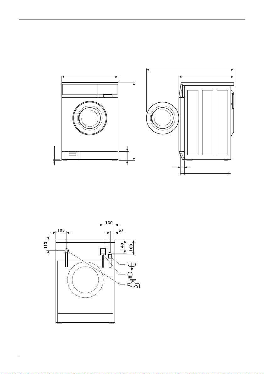
Appliance Dimensions
Front and Side Views
598
+10
-5
850
+10
-5
10
Rear View
Appliances with cold water connection only
100
950
592
50
575
16
Page 5
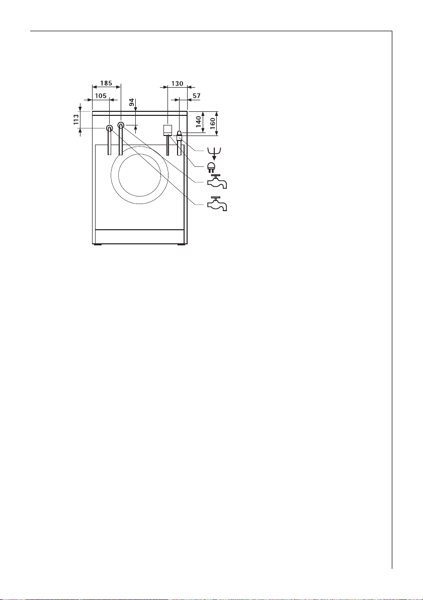
Appliances with hot and cold water connections
Hot water inlet
Cold water inlet
Appliance Installation
The appliance worktop must not be removed to gain a height reduction
3
when installing under a kitchen worktop.
Appliance Transit
• To prevent electrical components becoming wet when moving the
appliance, do not tip the washing machine onto it’s front or the left
hand side (viewed from the front).
• Do not transport the appliance without the transit packaging/bolts/
bar in place. Transporting the appliance without the transport
packaging/bolts/bar in place may cause damage to the product.
• Never lift the appliance by the door.
• The appliance is heavy, care must be taken when moving it.
17
Page 6

Appliance Installation
Removing Transit Packaging
• Ensure all transit packaging is removed prior to installation.
• Retain transit packaging for future use.
F
G
E
C
C
B
B
D
H
A
The appliance is supplied with a spanner (H) and plastic caps (E) (2 pcs.)
3
and (G) (1 pc).
0 Remove the hose holder (A).
0 Remove the 2 screws (B) with the spanner supplied (H).
0 Remove the 4 screws (C).
0 Remove the transit bar (D).
0 Cover the holes left by screws (B) the 2 plastic caps (E).
0 Replace the 4 screws (C), for safe keeping.
0 Remove the screw and compression spring (F) with the spanner (H),
cover the hole with plastic cap (G).
Important: When fitting the plastic caps, press until they snap into the
rear panel securely.
18
Page 7

Appliance Installation
Installation-Site Preparation
• The installation surface must be clean, dry and level.
• Do not install on deep pile carpet.
• If the appliance ist installed next to heat source (e. g. cooking
appliance), a heat insulating pad (85 x 57 cm) must be placed
between the washing machine and the heat source.
• Do not install the appliance in locations where the temperature may
fall below freezing.
• Please ensure that when the appliance is installed it is easily
accessible for the engineer in the event of a breakdown.
Installation on a Suspended Floor
Suspended wooden floors are particularly susceptible to vibration. To
help prevent vibration we recommend you place a waterproof wood
panel, at least 15 mm thick under the appliance, secured to at least 2
floor beams with screws. If possible install the appliance in one of the
corners of the room, where the floor is more stable.
Levelling the Appliance
• The appliance must be levelled using the adjustable feet.
• Adjust the feet using the spanner provided.
• Ensure the spanner is securely pushed onto the hex head on the feet
of the appliance.
• Adjust the feet so that the appliance is level. The appliance must not
rock when weight is applied.
• Check the appliance level using a spirit level.
• Never use strips or shims of wood or cardboard etc to compensate for
any uneveness in the floor. Always use the adjustable feet.
Self Adjusting Foot
Appliances with a spin speed of 1400 r. p. m. and over have a self
adjusting foot fitted (rear right).
• If the appliance vibrates or is unstable during a spin cycle of
1400 r. p. m.: Set the three adjustable feet to length of 10 mm.
• If the self adjusting foot (rear right) does not reach the floor:
Manually extend the self adjusting foot to the required length.
19
Page 8

Electrical Connection
Any electrical work required to install this appliance should be carried
out by a qualified electrician or competent person.
WARNING - THIS APPLIANCE MUST BE EARTHED.
1
The manufacturer declines any liability should these safety
measures not be observed.
Before switching on, make sure the electricity supply voltage is the
same as that indicated on the appliance rating plate. The rating plate is
located at the top of the rim of the open door.
The appliance is supplied with a 13amp plug fitted. In the event of
having to change the fuse in the plug supplied, a 13amp ASTA
approved (BS 1362) fuse must be used.
20
Should the plug need to be
replaced for any reason. The
wires in the mains lead are
coloured in accordance with
the following code:
Green and Yellow : Earth
Blue : Neutral
Brown : Live
Blue
Green
& Yellow
Brown
Cord Clamp
Page 9

Electrical Connection
• The wire coloured green and yellow must be connected to the
terminal marked with the letter “E“ or by the earth symbol or
coloured green and yellow.
• The wire coloured blue must be connected to the terminal “N“ or
coloured black.
• The wire coloured brown must be connected to the terminal marked
“L“ or coloured red.
• Upon completion there must be not cut, or stray strands of wire
present and the cord clamp must be secure over the outer sheath.
WARNING: A cut off plug inserted into a 13 amp socket is a serious
1
safety (shock) hazard. Ensure that the cut off plug is disposed of
safely.
Permanent connection
In the case of a permanent connection it is necessary that you install a
double pole switch between the appliance and the electricity supply
(mains), with a minimum gap of 3 mm between the switch contacts
and of a type suitable for the required load in compliance with the
current electrical regulations.
The switch must not break the yellow and green earth cable at any
point.
This appliance is in accordance with the following EU Guidelines:
;
– Low Voltage Guidelines 73/23 EEC dated 19 February 1973, include
Guideline Change Notice 93/68 EEC
– EMC Guideline 89/336 EEC dated 3 May 1989, including Guideline
Change Notice 92/31 EEC.
This appliance complies with the requirements laid out in the EEC
Directive 76/899.
Voltage 240 V AC Fuse rating 13 amps
See rating plate for further information.
This appliance meets VDE requirements.
Particular regulations of local electricity authorities must be observed.
This appliance conforms to EEC Directive No. 82/499/EWG on radio
interference.
WARNING: Repairs to electrical appliances may only be performed by
1
trained personnel. Improper repairs may lead to serious risks for the
user.
21
Page 10

Water Connection
The washing machine is provided with safety devices preventing back-
3
contamination of the water supply and complies with local water
authority requirements.
This appliance is designed to be permanently plumbed into your home’s
water supply.
Before connecting up the machine to new pipework or to pipework
that has not been used for some time, run off a reasonable amount of
water to flush out any debris that may have collected in the pipes.
Water Pressure
The appliance is designed to operate within the following water
pressure limits:
– minimum 1 bar (14.5 p. s. i.)
– maximum 10 bar (145 p. s. i.)
IMPORTANT
• At more than 10 bar (145 p. s. i.): Install pressure-reducing valve.
• At less than 1 bar (14.5 p. s. i.): Unscrew the inlet hose from the
appliance at the inlet solenoid valve and remove the flow regulator
(to do this, remove the sieve with needle-nose pliers and remove
rubber washer behind the sieve). Replace sieve. Retain the washer for
future use.
Inlet Hose Connection
The inlet hose provided is 1.2 or 1.3 metres depending on the model. If
a longer inlet hose is required contact your AEG Service Force Centre.
Under no circumstances should hoses be connected together to provide
a longer length.
The rubber washers are either set into the inlet hose threaded
connection or supplied separately in the installation kit. These washers
must be fitted to ensure water tight seals. Do not use any other washer.
22
Page 11

0 Connect the hose to the machine with
the right angled connector.
IMPORTANT:
Do not overtighten the plastic nuts on
the threaded connectors.
Rubber Washer
0 Connect the hose end with a straight
connector to the water supply tap with
an 3/4" thread.
Rubber Washer
IMPORTANT:
Do not overtighten the plastic nuts on
Fine Filter
the inlet hose threaded connectors.
WARNING:
Open the water taps slowly and check the connections are
watertight before final positioning of the machine.
23
Page 12

Water Connection
Appliances with hot and cold water fill
Washing machines with hot and cold fill should be connected as shown
below.
hot
cold
hot
WARNING: The incoming hot water temperature must not
exceed 70°C.
If only a cold water supply is available, connect the two hoses to the cold
water outlet by means of a “Y“ connection piece. (A “Y“ piece is available
from your AEG Service Force Centre, part number 645430709).
24
Page 13

Water Connection
Water Drainage
The appliance drain hose should hook into a standpipe, the hook in the
drain hose is formed using the plastic “U-Piece“ supplied, with an
internal diameter of approximately 38 mm (see diagram) thus ensuring
there is an air break between the drain hose and standpipe.
When discharging into a standpipe ensure that the top of the
curve in the hose end is no more
that 90 cm (35.4’’) and no less
than 60 cm (23.6’’) above floor
level.
Max 90 cm (35,4“)
Min 60 cm (23,6“)
The upright standpipe should
have a minimum, length of
30 cm (12’’) from the bottom of
the elbow to the top of the pipe
(see diagram). Make sure that it
is designed in such a way that
the end of the drain hose
cannot be covered with water.
Longer drain hoses are available
in lengths of 2.7 and 4 metres
from your AEG Service Force
Centre.
If you intend the drain hose
from the washing machine to
empty into a sink, make sure
that the sink is empty and the
plug hose is not blocked. Use
the plastic “U-Piece“ supplied.
38mm (11/2“)
diameter standpipe
Min 30 cm (12“)
25
Page 14

AEG Service Force
If you wish to contact your local AEG Service Force Centre for advice or
spare parts, telephone:
0990 234234
26
 Loading...