

Page 1
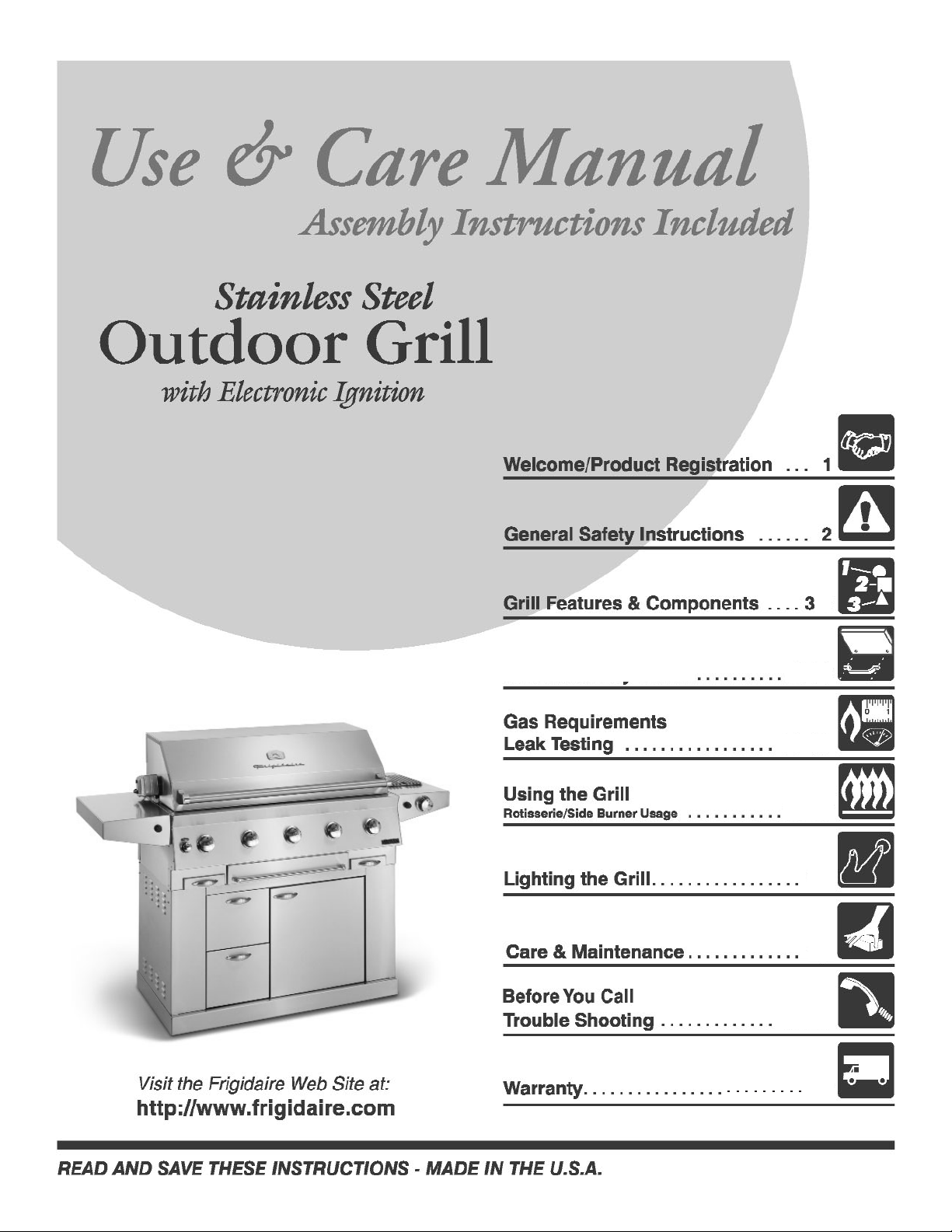
Grill Assembly
Built-In Instructions
4-8
9-11
17-18
12-15
13
16
19
44”
Gallery Series
Page 2
Welcome & Congratulations
Please record Grill information for future reference and service work:
Model #:
Serial #:
Date of Purchase:
Gas Type:
Please retain this manual for future reference
© 2004 Electrolux Home Products, Inc All rights reserved
Congratulations on your purchase of a new gas grill! At Electrolux Home Products, we
are very proud of our product and are completely committed to providing you with the
best service possible. Your satisfaction is our number one priority.
We know you’ll enjoy your new gas grill and Thank You for choosing our product. We
hope you consider us for future purchases.
PLEASE CAREFULLY READ AND SAVE THESE INSTRUCTIONS
This Use & Care Manual provides specific operating instruction for your model. Use your
gas grill only as instructed in this manual. These instructions are not meant to cover every
possible condition and situation that may occur. Common sense and caution must be
practiced when installing, operating and maintaining any appliance.
Questions? 1-800-320-0859
1
Page 3
TESTED IN ACCORDANCE WITH ANSI
Z21.58b-2002/CGA 1.6b-M02 STANDARD FOR
OUTDOOR COOKING GAS APPLIANCES.
THIS GRILL IS FOR OUTDOOR USE ONLY.
Check your local building codes for the proper
method of installation. In the absence of local
codes, this unit should be installed in accordance
with the National Fuel Gas Code No. Z223.1-2002
and the National Electrical Code ANSI/NFPA No.
70-1990
WARNING
DO NOT try lighting this appliance without reading
the “LIGHTING INSTRUCTIONS” section of this
manual.
FOR YOUR SAFETY
DO NOT store or use gasoline or other flammable vapors and
liquids in the vicinity of this or any other appliance.
An LP cylinder not connected for use shall not be stored
in
the vicinity of this or any other appliance.
2
General Safety Instructions
IMPORTANT SAFETY INFORMATION
-
Read this manual carefully before using your grill to reduce the risk of fire, burn hazard or
other injury.
- Extreme care should be used because of the high temperatures produced by this appliance. CHILDREN SHOULD NOT BE LEFT
UNATTENDED IN AN AREA WHERE THE GRILL IS BEING OPERATED.
- This appliance must be kept clear from combustible materials, gasoline or other flammable vapors and liquids. Do not allow
flammable materials to come in contact with grate, burner or hot surfaces.
- Do not repair or replace any part of this appliance unless it is specifically recommended in this manual. A qualified service technician should conduct all other service.
- Follow the installation and servicing instructions provided with this product. Have your grill installed by a qualified service technician. Locate the main gas supply valve so that you know how to shut the gas off to your grill. If you smell gas, make sure all gas
connections are tight before operation. If you continue to smell gas call a qualified technician.
- When lighting a burner, always pay close attention to what you are doing. Be certain you are pushing the ignitor that lights the
burner you intend on using.
FOR YOUR SAFETY
If you smell gas:
1. Shut off gas to the appliance.
2. Extinguish any open flames.
3. Open lid.
4. If odor continues, immediately
call your gas supplier.
FOR OUTDOOR USE ONLY
This appliance is not intended to be
installed in or on recreational vehicles or boats.
CALIFORNIA PROPOSITION 65 - WARN-
ING: The Burning of gas cooking fuels generates
some by products which are on the list of substances
which are known by the State of California to cause
cancer or reproductive harm. California law requires
businesses to warn customers of potential exposure to
such substances. To minimize exposure to these substances, always operate this unit according to the use
and care manual, ensuring you provide good ventila-
tion when cooking with gas.
Page 4
3
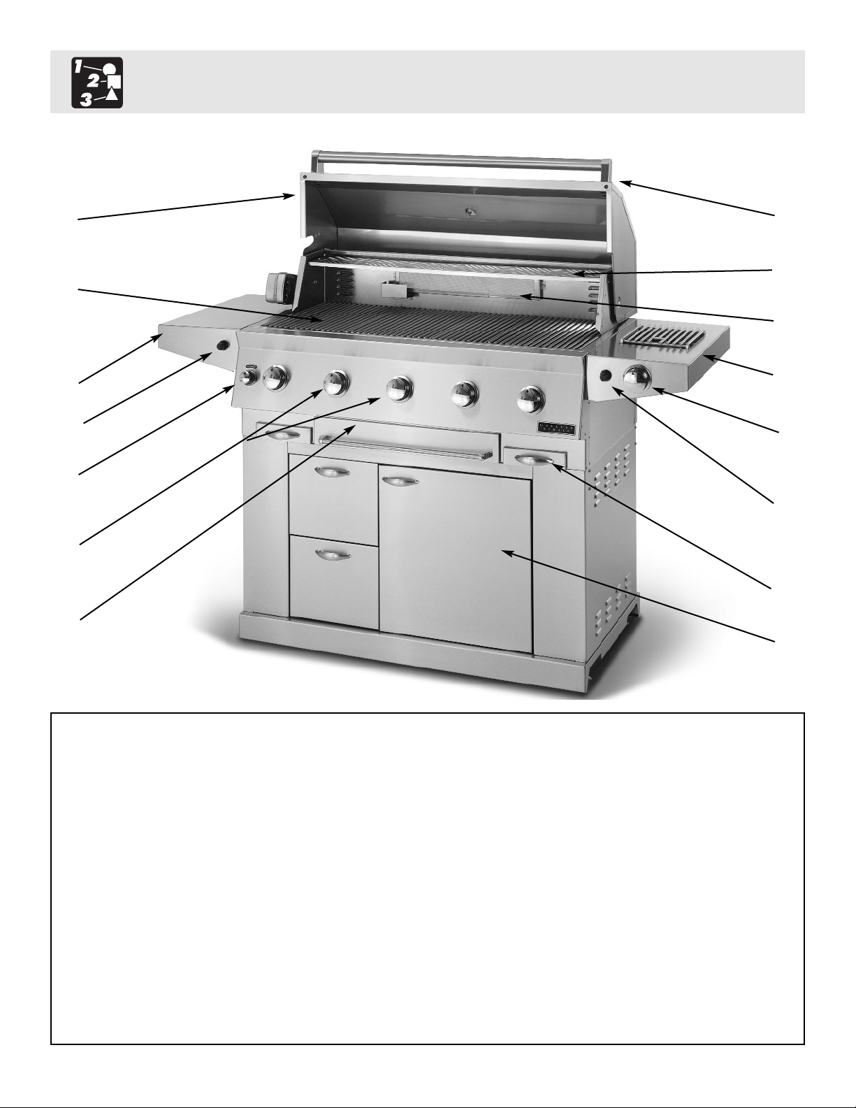
1. Roll top grill hood 8. Warming shelf
2. Grilling/Cooking surface 9. Infrared back burner
3. Side Shelf 10. Electronic ignitors: main, rear infrared
& side burner
4. Control knob: back infrared burner 11. Cart w/doors
5. Control knobs: main burners 12. Drip Pans
6. Warming drawer 13. Side Burner
7. Handle 14. Control knob:side burner
2
1
7
8
9
13
14
10
10
12
11
5
6
4
3
Grill Features: GL44
Page 5
4
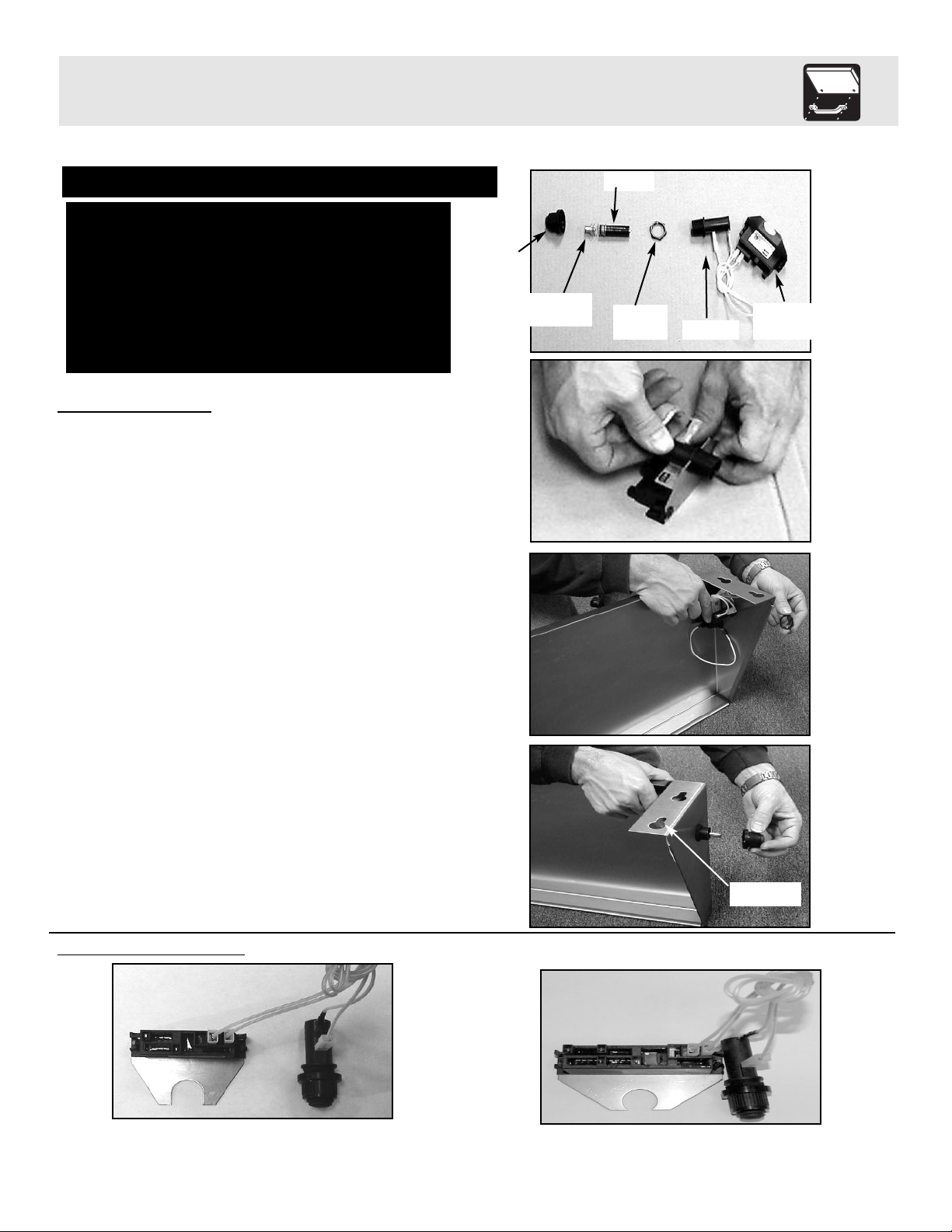
Ignitor Attachment
1. Remove the ignitor cap, spring assembly, battery and lock nut from ignitor. (See Fig. 1)
2. Insert the threaded section of the ignitor into
the U-shaped cut out of the ignitor mounting
bracket. (See Fig. 2)
3. Insert the threaded section of the ignitor
through the hole in the shelf and secure to
shelf using the lock nut. (Use the ignitor
assembly diagrams to determine which
ignitor goes with which shelf depending on
grill model.) Tighten Securely. (See Fig. 3)
4. Re-insert the battery, positive side first, and
spring assembly and attach the ignitor cap.
(See Fig. 4)
5. Repeat above steps for second ignitor
on the Side Burner.
GL44 Ignitor
Assembly
Fig. 1
Fig. 2
Fig. 3
Fig. 4
Note: Prior to assembly remove protective film from stainless steel parts
Assembly requires: 4 tools and a Friend
Tools required:
1/4” socket wrench
1/2” socket wrench
adjustable wrench
scissors
Grill Assembly
Side Burner (Three Wire)
Left Shelf (Double Wire)
Cap
Battery
Spring
Assembly
Locking
Nut
Cylinder
Mounting
Bracket
Keyhole
Page 6
5
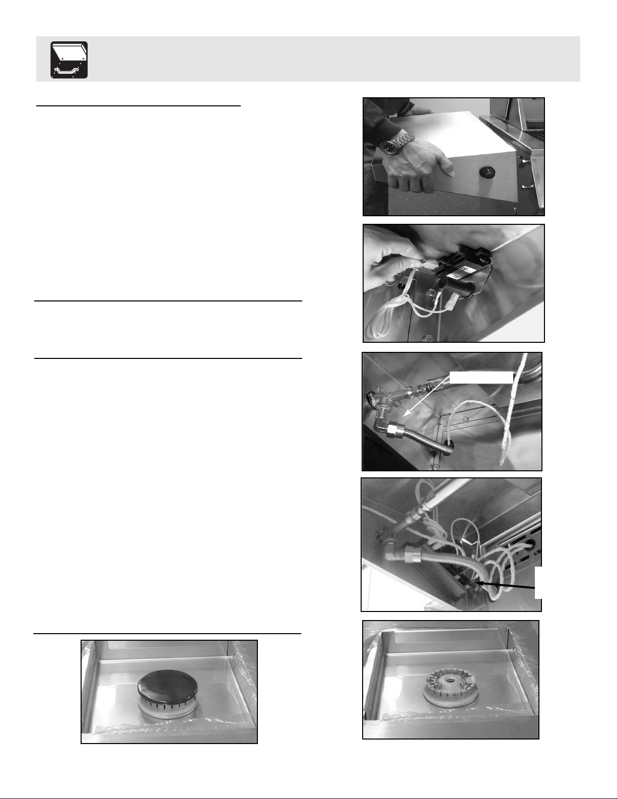
Side Shelf and Side Burner Attachment
1. Loosen the bolts on the side of the grill and
attach the shelf by allowing the bolt heads to
fall through the large opening in the bottom of
the keyhole slots. Then slide the shelves
downward until the bolts are resting against
the top of the key hole slots. Tighten all of
the shelf bolts. (See Fig. 5)
2. Attach the wires coming out from the sides of
the grill to the ignitor terminals. (See Fig. 6)
Note: It does not matter which wire goes to which
terminal on the double wire ignitor
1. Attach the side burner by allowing the bolt
heads to fall through the large opening in the
bottom of the keyhole slots. Then slide the
side burner downward until the bolts are
resting against the top of the key hole slots.
Tighten all of the side burner bolts.
2. Screw the Flex Line coming from the side of
the grill to the fitting on the bottom of the
Side Burner. (See Fig. 7)
3. Attach the ignitor wires coming out from the
side of the grill to ignitor terminals.
(See Fig. 8)
Note: It does not matter which wire goes to which
terminal on the three wire ignitor
4. Install burner into side burner tray lining up
the three cutouts on the underside of the
burner. (See Fig. 9)
5. Install burner cap onto burner (See Fig. 10)
Side Shelf/Side Burner Assembly
Fig. 5
Fig. 6
Fig. 7
Fig. 8
Fig. 9
Fig. 10
Attach to fitting
Ignitor
wires
hookup
Page 7
Grill Assembly
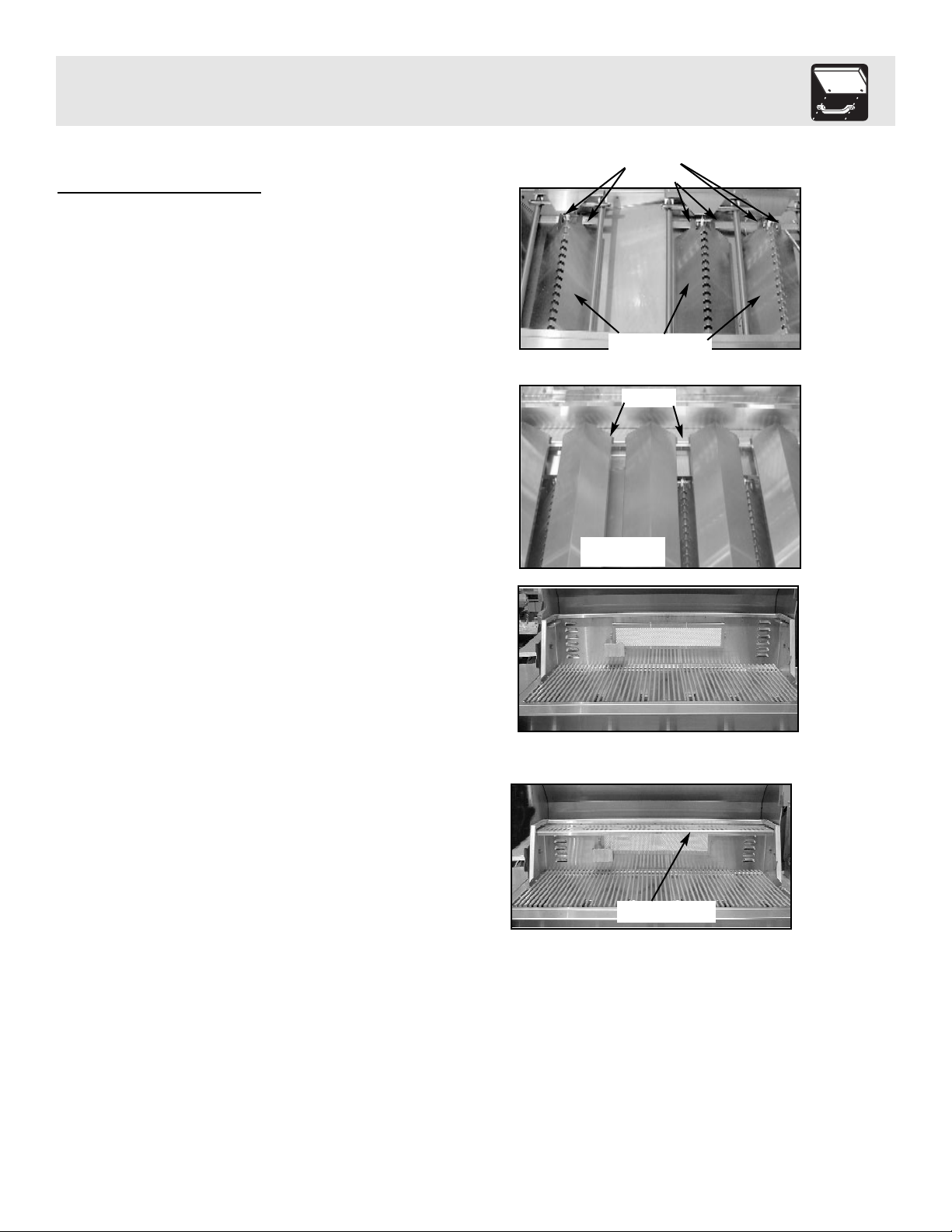
Interior parts installation
1. Check to make sure the bottom Flavor
Grids are correctly installed in the cutouts and
around the ignitors, as they may have shifted
during shipment. (See Fig. 9)
2. Insert the second row of Flavor Grids to cover
the main burners into cutouts with triangle
ridges facing up. (See Fig. 10)
3. Install cooking grates on the ledges provided
on the grill to create your cooking surface.
(See. Fig. 11)
4. Place warming shelf on support brackets by
setting it flat across brackets allowing the two
holes to line up with the stops on each
bracket. (See Fig. 12)
Bottom Flavor Grids
in between burners
Fig. 9
Fig. 11
Fig. 10
Fig. 12
6
Warming Shelf
Cutouts
Top Flavor Grids
cover burners
Cutouts
Page 8
7
Built-In Instructions
Planning and Design
Start by identifying the number and size of components you want to include: Grill, side burner, access
doors for storage or other items you may wish to furnish such as: refrigerator, sink, warming drawer.
Countertops must be constructed with non-combustible, outdoor-safe materials. Consider outdoor lighting to
illuminate after-dark Grilling. For assistance in designing and building your outdoor cooking center, contact a
landscape architect or general contractor. Review the drawings on the following pages to determine the exact
dimensions and items needed for a built-in Grill. Keep in mind that the gas line hook-up is on the right hand
side for the main Grill head. The structure, Grill and support items must be kept level throughout the
installation to ensure proper operation.
Location
Take into account convenience and visual impact as well as traffic flow, wind exposure, and the site’s
structural suitability. The Grill should never be placed in an enclosed area without an approved ventilation
system, or beneath a combustible overhang. Because the Grill exhausts to the rear, it should never be located in
front of a window or less than 12” from hard-to-clean surfaces. We recommend keeping your gas supply lines
as short as possible for best performance. To ensure a perfect fit, we strongly recommend that you have all
components on hand prior to final construction.
Clearance to Non-Combustible Construction
For your safety a minimum of 3” clearance from the back of the Grill to non-combustible construction is
required. You should allow at least 6” side clearance to non-combustible construction. The Frigidaire Grill
can be placed directly adjacent to non-combustible construction below the cooking surface.
Outboard Ignitor Plate Installation
The electronic ignitor requires a standard size electrical box, (available at a local hardware store), with a
minimum depth of 2.5” to be mounted in the structure. It should be placed on the left front or left side of the
built-in island, with the center of the ignitor button no more than 3”-5” from the Grill. The ignitor plate,
sold separately, fits over the standard electrical box once mounted in the structure. (See drawing on following
page). The ground wire for the ignitor needs to be grounded to a metal structure in order for the ignitor to work.
Utilities
For natural gas Grills, consult your local gas utility company for hook-up requirements. All gas connections
should be made by a plumber or a gas supply company. For natural gas installation, the supply line must be at
least 1/2” diameter. The rotisserie requires a 110/120 volt electric supply and GFI receptacle. (6.5 amp min.)
If your plan includes a sink, arrange for your plumber to run a water line to the site.
The Frigidaire Grill can be installed as a built-in Grill. If installed as a built-in Grill, the Grill
surround must be constructed of Non-combustible material.
Page 9
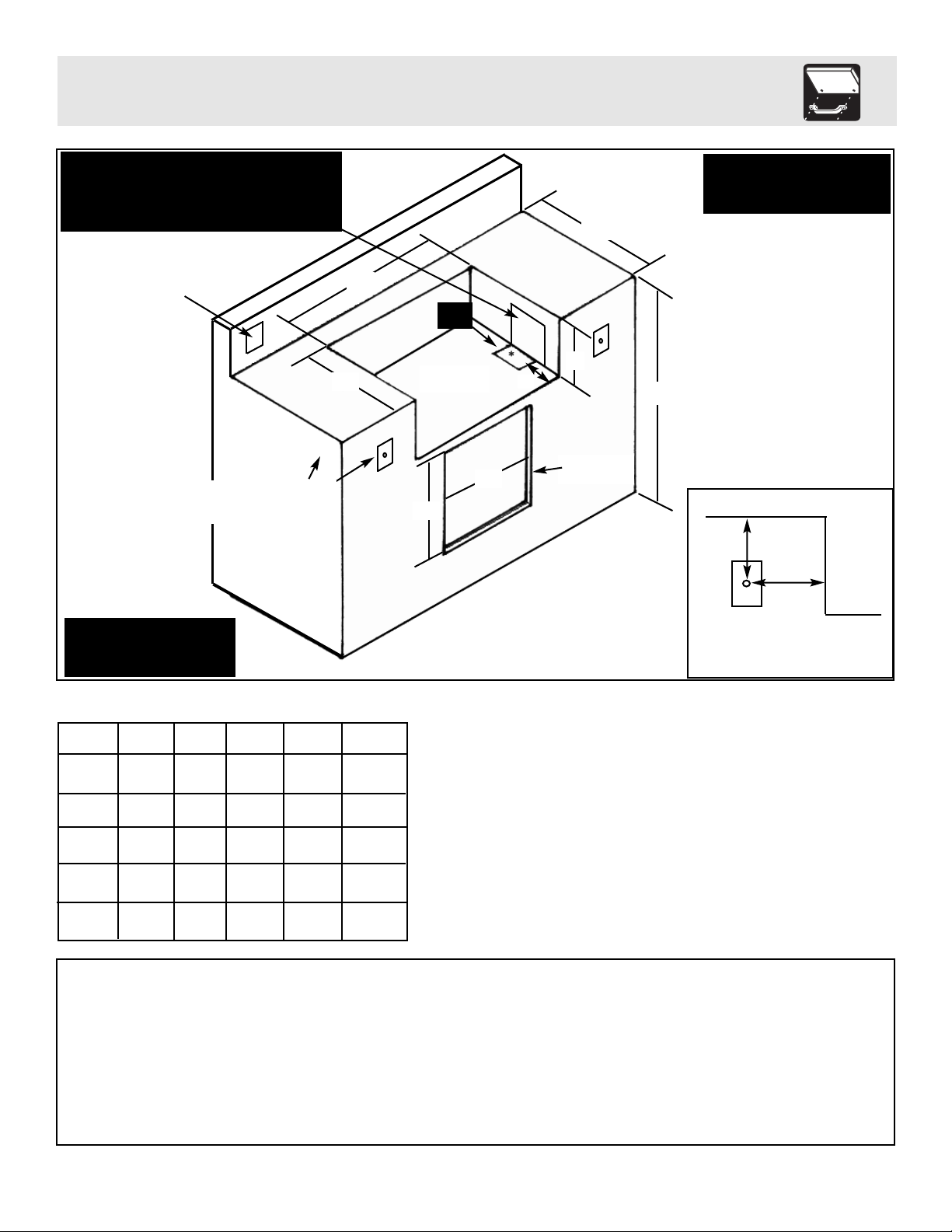
Built-In Instructions
8
35 1/2” Max.
27 1/2” Min.
B
D
E
C
*Gas
Cutout
2”
Opening for
access door(s)
A
B
C
D
E
51”
Grill
51 1/8”
20 7/8”
13
1
/16”
N/A
N/A
44”
Grill
44 1/8”
20
7
/8”
13
1
/16”
N/A
N/A
57”
Grill
57 1/8”
25 1/4”
13
1
/16”
N/A
N/A
Single
Access
Door
N/A
N/A
N/A
18
1
/4”
18
1
/2”
Dual
Access Door
N/A
N/A
N/A
36
1
/8”
18
1
/2”
Additional Requirements:
*Gas connection cut out in floor support needs to be 4” wide x 6” long, set 6” back from front edge.
*Ignitor cutout is equal to a standard electrical outlet with a minimum depth of 2
1
/2”.
*If using a backsplash apron or rear wall, locate electrical service on the left hand side for rotisserie motor connection.
*A minimum clearance of 12” from the back must be maintained between the grill and any combustible construction such as wood
siding of a residence, 3” minimum for non-combustible construction.
3”- 5”
3”- 5”
Grill
Maximum distance to center of
ignitor button from side of grill
IGNITOR PLATE
INSTALLATION
Side cutouts are needed on each side to feed ignitor
wires to the ignitor plates and allow access to side gas
connections
(Size: 10” high x 5” long, set 1” back from front edge)
A
GFI Electrical outlet
for rotisserie motor
(6.5 amp min.)
Built-in Dimensions
Floor Support
area for grill
Note: Make sure to use a
non-combustible base and
sides for the structure
*A minimum 3” clearance is
required between the back of the
grill hood and a non-combustible
surface.
counter top
*Required Ignitor cutout
for front or side mount
Page 10
9
General Information
Verify the type of gas supply to be used, either Natural Gas (NG) or Liquid Propane (L.P)., and make sure the
marking plate (located on the back of the unit) agrees with that of the supply.
Note: Never attach an unregulated gas line to the appliance.
For Natural Gas installations, an installer must supply a gas shutoff valve that is easily accessible to the grill.
All installer supplied parts must conform to local codes, or in the absence of local codes, with the National
Electrical Code, ANSI/NFPA 70-1990, and the National Fuel Gas Code, ANSI Z223.1-1998.
All pipe sealants must be an approved type and resistant to the actions of L.P. gases. Never use pipe sealant
on flare fittings. All gas connections should be made by a competent technician and in accordance with local
codes and ordinances. In the absence of local codes, the installation must comply with the National Fuel Gas
Code, ANSI Z223.1-1998. Gas conversions kits are available from the factory. When ordering gas conversion
kits have the model number, and the type of gas (natural or L.P.) from your grill.
This appliance and its individual shut off valve must be disconnected from the gas supply piping system during any pressure testing of that system at test pressures in excess of 1/2 PSIG (3.5 kPa.).
This appliance must be isolated from the gas supply piping system by closing its individual manual shut-off
valve during any pressure testing of the gas supply piping system at test pressures equal to or less than 1/2
PSIG (3.5 kPa.).
The installation of this appliance must conform with local codes, or in the absence of local codes , with
National Fuel Code, ANSI Z223.1a-1998.
Installation in Canada must be in accordance with the Standard Can1-b149.1 and or .2 (installation code for
gas burning appliances and equipment) and local codes.
Natural Gas Installation
The gas inlet supply pressure should be between 5” and 14” w.c. A step down regulator is required if the line
pressure is in excess of 14” w.c.
Check your local gas utility company or with local codes for instructions on installing gas supply lines. Be
sure to check on type and size of run, and how deep to bury the line. If the gas supply line is too small, the
grill will not operate correctly.
Any joint sealant used must be an approved type and be resistant to the actions of L.P. gases.
Place the installer supplied shut-off valve in an accessible location to enable the gas supply to be cut off to the
unit.
Gas Requirements
Page 11
L.P. Gas Installation
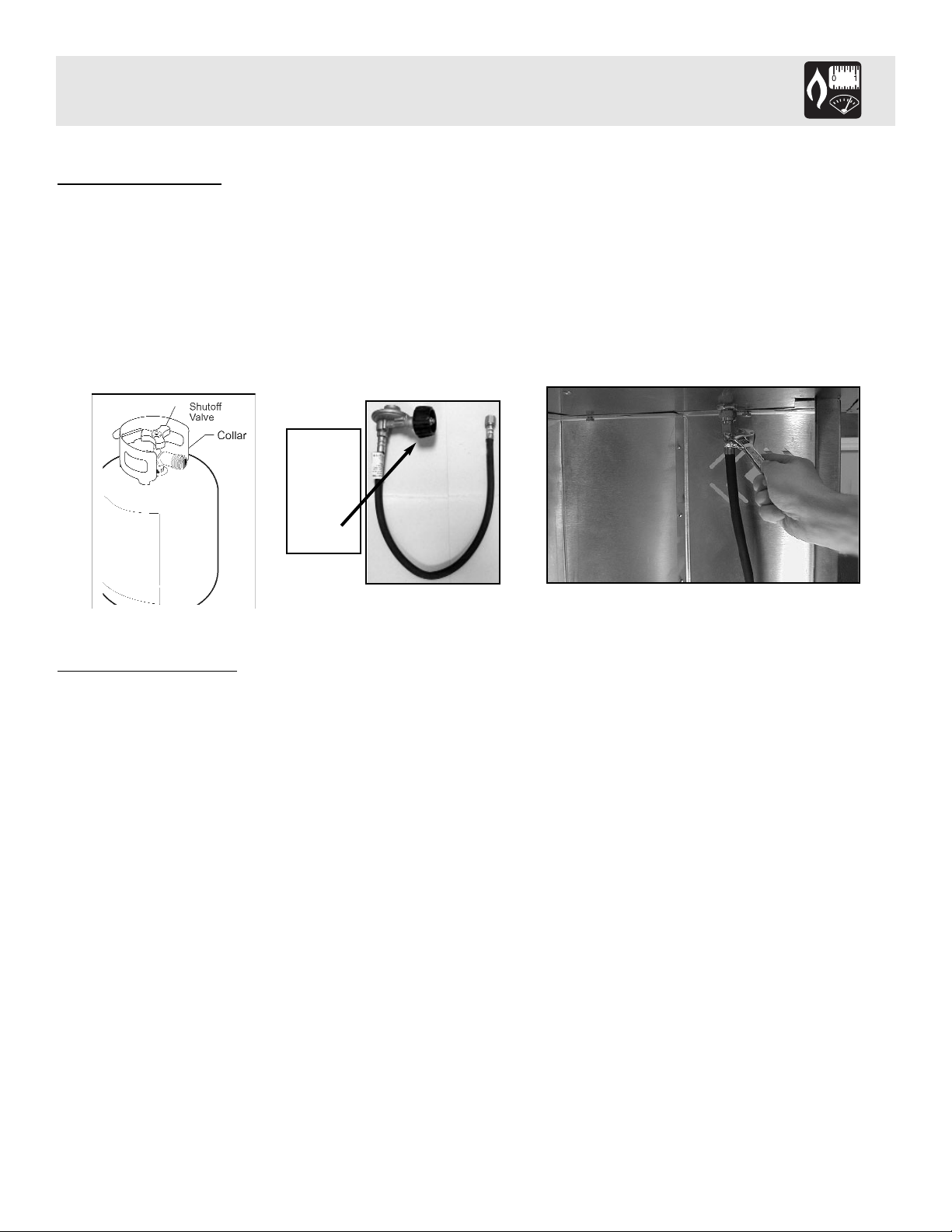
Frigidaire Gas Grills that are set to operate with L.P. gas come with a high capacity hose and regulator
assembly. (Note: Only use the pressure regulator and hose assembly supplied with the grill or a
replacement pressure regulator and hose assemblies specified by Frigidaire). This assembly is designed
to connect directly to a standard 20 lb. L.P. cylinder.
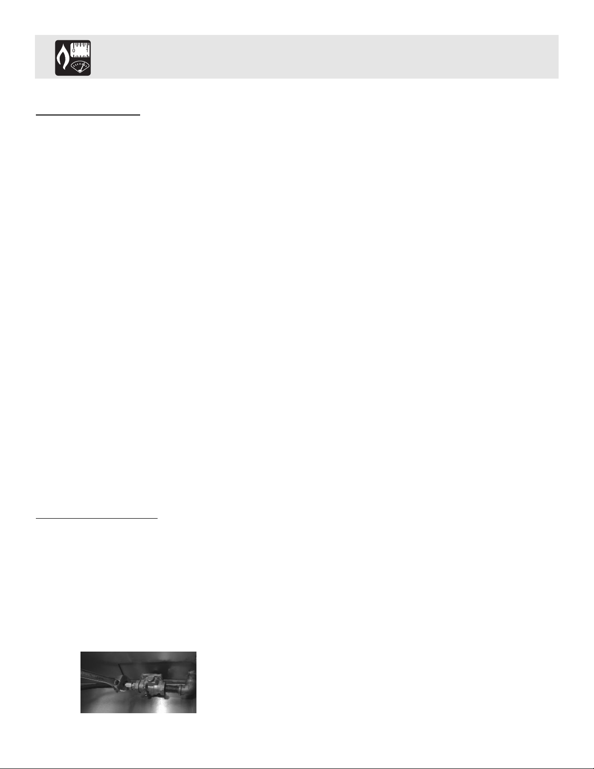
Attach the gas hose assembly to the brass 3/8 flared fitting using an adjustable wrench on the under side of the
grill. Tighten securely and attach other end to the propane tank. (sold separately) (See Fig. 13)
L.P
. Tank Information
Never use a dented or rusted L.P. tank or cylinder with a damaged valve.
The L.P. cylinder must be provided with a shut-off valve terminating in an L.P. gas supply cylinder outlet
specified, as applicable, for connection No. 510 in the standard for compressed gas cylinder valve outlet and
inlet connection ANSI/CGA-V-1. Cylinders must not be stored in a building, garage, or any other enclosed
area. (The L.P. cylinder must have an overfill protection device, OPD, on it.)
The L.P. Gas supply cylinder must be constructed and marked in accordance with the specifications for L.P.
gas cylinders of the U.S. Department of Transportation (DOT) or the National Standard of Canada,
CAN/CAS-B339, “Cylinders, Spheres and Tubes for the Transportation of Dangerous Goods.”
•When not in use, gas supply cylinder valve is to be in the “OFF” position.
•The tank supply system must be arranged for vapor withdrawal. (LP Tank must be kept in an upright
position.)
•The regulator and hose assembly must be inspected before each use of the grill. If there is excessive abrasion
or wear or if the hose is cut, it must be replaced prior to the grill being used again.
•Cylinders must be stored outdoors out of the reach of children and must not be stored in a building, garage or
any other enclosed area.
•Never fill the cylinder beyond 80% full
•Do not store a spare LP-gas cylinder under or near this appliance
10
LP hose/
regulator
supplied
with grill.
(Type 1
connector)
Gas Requirements
Fig. 13
Page 12

General Information
Although all gas connections on the grill are leaked tested at the factory prior to shipment, a complete gas
tightness check must be performed at the installation site due to possible mishandling in shipment, or excessive pressure unknowingly being applied to the unit. Periodically check the whole system for leaks, or immediately check if the smell of gas is detected.
Befor
e T
esting
Do Not smoke while leak testing. Extinguish all open flames. Never leak test with an open flame.
Mix a solution of equal parts mild detergent or liquid soap and water.
T
esting
1. Turn off the burner control knobs.
2. Turn the top knob of the fuel supply cylinder counterclockwise (right to left) one rotation to
open.
3. Apply the soap solution to connections of the fuel supply assembly. If no soap bubbles
appear, the grill is ok to use. If bubbles form at the connections, a leak is detected.
(If a leak is detected, immediately turn off the gas supply, tighten any leaking fittings, turn gas on,
and recheck).
4. Turn off the knob on the fuel supply cylinder.
5. Turn on the burner control knobs for a moment to release the pressure in the hose, then turn
the control knobs back off.
6. Wash off soapy solution with cold water and towel dry.
Check all gas supply fittings before each use and each time the gas supply cylinder is connected to the regulator. Leak test any time a part of the gas system is replaced. Perform a leak test at least once a year whether or
not the L.P. gas supply cylinder has been disconnected.
11
Note: If you cannot stop a gas leak turn off the gas supply and call your local gas utility, or
the dealer you purchased the appliance from. If necessary, replace the faulty part with
a manufacture recommended replacement part.
Leak Testing
Page 13

Grill Location
Do not use the grill in garages, breezeway, sheds or any enclosed area. Never operate the grill in enclosed
areas as this could lead to a carbon monoxide buildup, which could result in injury or death. Place the grill on
a level surface. Avoid moving the grill while it is operation.
Note: The grill will operate best if it is not facing directly into the wind.
Clearance to combustible construction - A minimum of 12” from the sides and back must be maintained from
the gas grill above and below the cooking surface to adjacent vertical combustible construction.
Clearance to non-combustible construction - A minimum of 3” clearance from the back of the grill to noncombustible construction is required for the lid to fully open.
General Rules
Do Not leave the grill unattended while cooking!
1. Make sure the grill has been leak tested and is properly located.
2. Light the grill burners using the instructions on this page.
3. Turn the control knobs to “High” and preheat the grill for 10 minutes.
4. Place the food on the grill and cook to the desired doneness. Adjust heat setting between “High”
and “Low” if necessary.
5. Allow grill to cool down and clean the drip tray after each use.
*Keep any electrical supply cord and the fuel supply hose away from any heated surfaces.
*The location of the burner tube with respect to the the orifice is vital for safe operation. Check to
ensure the orifice is inside of the burner tube before using your grill. This is Very Important.
12
Using the Grill
Page 14
Before Lighting
Warning: Important! Before Lighting...
Check the gas supply line for cuts, wear or abrasion.
Always keep your face and body as far away from the
grill as possible when lighting.
Grill Burner
Lighting
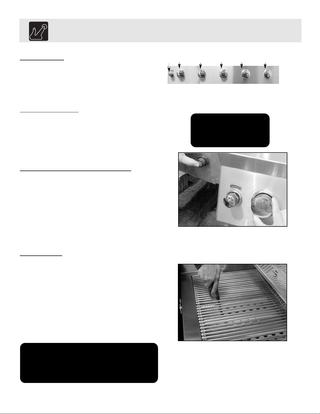
This unit comes equipped with (2) electronic starters
and (4) electrodes. The electronic starter located on the
right shelf lights the Side Burner. The electronic starter
on the left shelf lights the Main Burners, which are controlled by Knobs 1,2,3,4 & 5. The left electronic starter
also lights the Back Infrared Burner.
Lighting the Grill with electr
onic ignitors
Always open the lid before attempting lighting.
Push and turn one of the control knobs counter clockwise to the “HIGH” position and immediately press
the electronic ignitor button. You’ll hear a snapping
sound. It may be necessary to hold the electronic
starter button for about 4 seconds. If the burner does
not light in 4 seconds, turn the knob to OFF and wait
5 minutes before trying again. Repeat above steps to
light remaining burners. (See Fig. 14)
Match Lighting
If by chance the electronic ignitor does not light the
burner, the burner may be lit with a match. Keep
your face as far away from the Grill surface as
possible and pass a lit, long stem match through the
spaces in the Grill rack to the ports of the back
crossover burner between the flavor grids. Position
the match near the burner ports and push and turn the
control knob counter clockwise to the “HIGH”
position. (See Fig. 15)
13
Do not attempt to
“Light” the grill if the
odor of gas is present!!
Fig. 14
Fig. 15
Note: If the grill will not light after
several attempts see the Troubleshooting section of this manual.
Turn the control knobs to the OFF
position when not in use.
Lighting the Grill
Right electric starter for
Side Burner
Left electric starter
For Main Burners #1,
#2, #3, #4 & #6 and
Back Infrared Burner
Back
Infrared
Knob
#1
Knob
#4
Knob
#5
Knob
#3
Knob
#2
Page 15
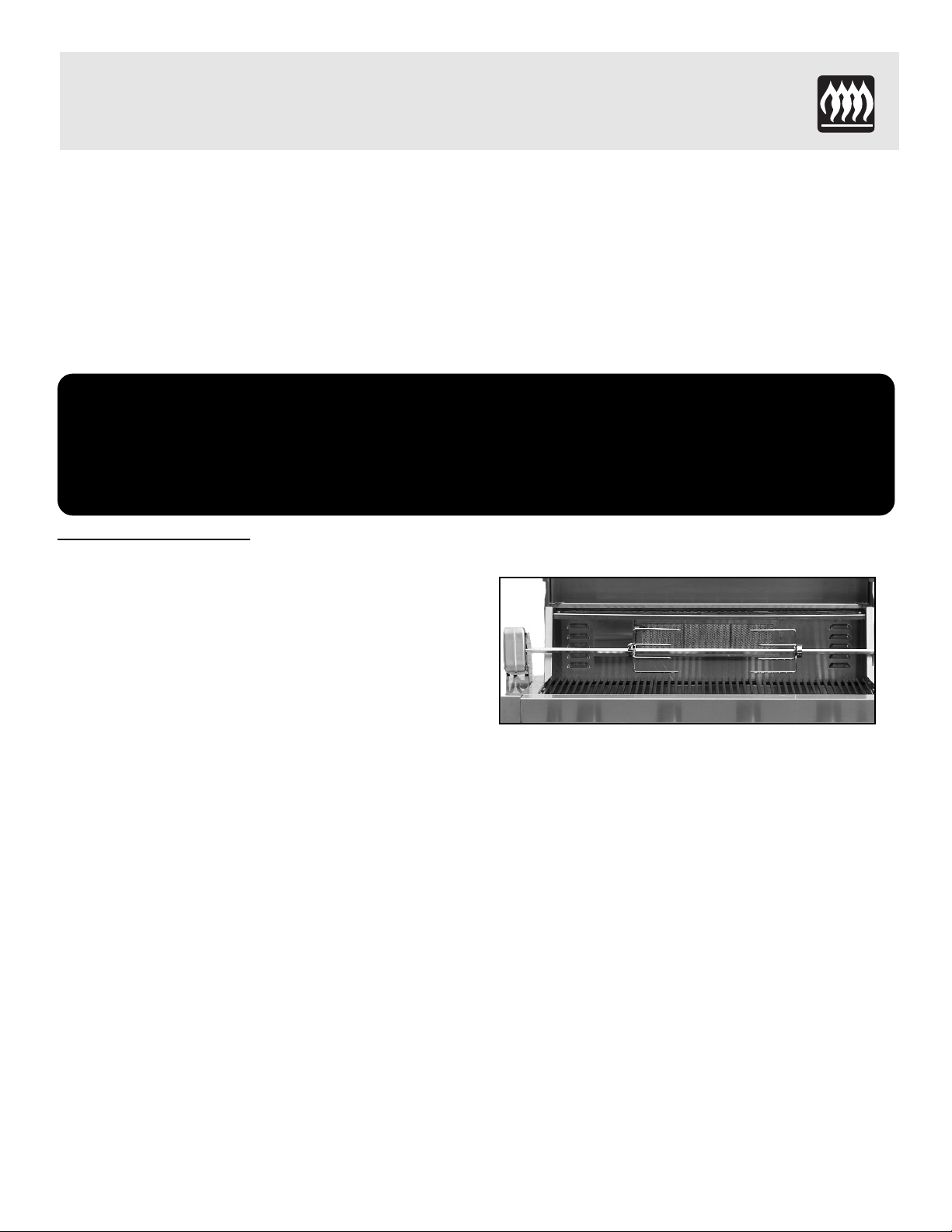
The grill rotisserie system is designed to cook items from the back using infrared heat. The rotisserie burner
is an infrared type which provides intense searing radiant heat. Preferred by chefs over other cooking methods,
this intense heat is magnificent for searing in the natural juices and nutrients found in quality cuts of meats.
Once lit, the rotisserie burner will reach cooking temperatures in 1 minute. The orange/red glow will even out
in about 5 minutes. The rotisserie motor is equipped with metal gears and is capable of turning up to 20 lbs.
of food. The motor is mounted on a bracket on the left side of the grill by sliding the motor over the bracket
with the cord facing the back of the grill. Make sure the motor is straight prior to operating.
14
Attaching the Rotisserie
The motor is mounted on a bracket on the left side of
the grill by sliding the motor over the bracket with
the cord facing the back of the grill.
With the rotisserie motor in place and plugged into an
electrical outlet it is now ready to operate. After
installing rotis rod handle, slide one of the meat forks
onto the rod. (prongs facing away from the handle)
Push the rod through the center of the food, then slide
the second meat fork onto the rod. (prongs toward the
food). Center the food to be cooked on the rod, then
push the meat forks firmly together. Tighten the wing
nuts. It may also be necessary to wrap food with
butcher’s string, (never use nylon or plastic string) to
secure loose portions.
Once the food is secure, insert the pointed end of the
rotis rod into the motor assembly and rest the other
end on the support on the right-hand side of the Grill.
(If needed remove the cooking grates for more
room.). Turn the power switch to the “On” position
to start the rotisserie motor.
Note: Remove the rotisserie when not in use.
Remove warming shelf when using
rotisserie
Warning: Electrical Grounding Instructions
This appliance (rotisserie motor) is equipped with a three-prong (grounding) plug for
your protection against shock hazard and should be plugged directly into a properly
grounded three-prong receptacle. Do not cut or remove the grounding prong from this
plug.
Using the Rotisserie & Side Burner
Page 16
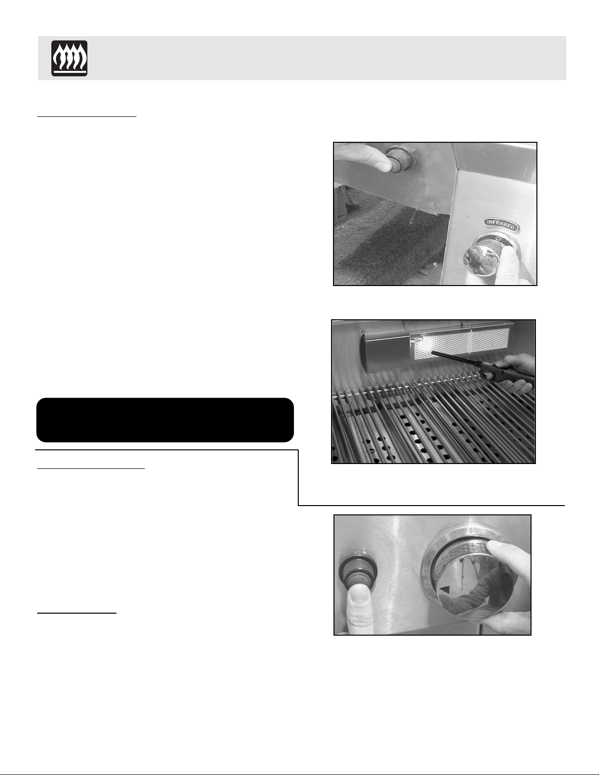
Rotisserie Lighting
Open the lid. Push and turn the control knob counter
clockwise to the “HIGH” position. Wait 5 seconds.
Then press and hold the electronic ignitor button.
You’ll hear a snapping sound. If the burner does not
light in 4 seconds, turn the control knob to OFF and
wait 5 minutes before trying again. Once lit, turn the
control knob to the desired setting. (See Fig. 16)
(If the ignitor does not function, the burner can be lit
by holding a lit match to the burner while the control
knob is turned counter clockwise to “HIGH”.)
(See Fig. 17)
NOTE: After the first use the stainless steel around
the burner will darken. This is a normal
occurrence of the non-rusting, type 304
stainless steel used on the grill. The infrared
panel will also darken after initial use. This is
a normal occurrence.
Side Burner
Lighting
Push and turn the control knob to the “HIGH”position and
immediately press and hold the electronic ignitor button.
You’ll hear a snapping sound. It may be necessary to hold
the electronic starter button for about 4 seconds. If the
burner does not light in 4 seconds, turn the knob to the
“OFF” position and wait 5 minutes before trying again.
Repeat above steps to light remaining burners.
(See Fig. 18)
Match Lighting
If by chance the electronic ignitor does not light the
burner, the burner may be lit with a match. Keep your
face as far away from the burner as possible and place a
lit, long stem match through the spaces in the grate to the
ports of the burner. Position the match near the burner
ports and push and turn the control knob to the
“HIGH”position.
15
Fig. 16
Fig. 17
Fig. 18
Note: Do Not operate the main burners
and infrared back burner at the
same time.
Using the Rotisserie & Side Burner
Page 17

Drip Tray
The drip tray located below the grill, inside the cart, should be cleaned periodically to prevent heavy buildup
of debris.
Note: Allow the drip tray to cool before attempting to clean.
Cooking Grates
The cooking grates can be cleaned immediately after cooking is completed and after turning off the flame.
Wear a barbecue mitt and scrub the cooking grates with a damp cloth. If the grill is allowed to cool down,
cleaning the grates will be easier if removed from the grill and cleaned with a mild detergent.
Stainless Steel
The grill is made from a non-rusting stainless steel. After initial usage, areas of the grill may discolor from
the intense heat given off by the burners, this is normal.
Purchase a mild stainless steel cleaner and rub in the direction of the grain of the metal. Specks of grease can
gather on the surface of the stainless steel and bake on to the surface and give a worn appearance. For
removal use an non-abrasive oven cleaner in conjunction with a stainless cleaner.
Note: Always scrub in the direction of the grain.
Rear
Infrared Burner:
Please light and burn the rear infrared burner at least once a month to ensure there is not a build-up of debris
or grease on the burner. This will ensure the ceramic burner will continue to operate as it should.
16
Care and Maintenance
Page 18
General
Trouble Shooting
You should inspect the burners at least once a year or immediately if any of the following conditions occur:
The smell of gas in conjunction with the burner flames appearing yellow.
The Grill does not reach temperature.
The burners make a popping noise.
The Grill heats unevenly.
Before calling customer service
If the Grill does not function properly, use the following checklist.
17
Problem
Grill will not light when the ignitor button is pushed.
Low heat with knob in “High” position.
Solution
After opening tank valve, be sure one of the
Grill control knobs is on high for at least 4
seconds while pushing ignitor button.
Check tank fuel level.
Check for loose wire connections.
Remove the cooking grates and flavor grids.
Push ignitor button, and check for spark on tip
of electrode.
Check to see if debris is blocking the
electrode sparks.
Check battery/replace battery.
Attempt to match light the burner.
If using L.P. gas, disconnect gas line at tank,
then reconnect.
Check for proper gas supply and pressure.
If using L.P. gas check for low fuel level.
If using L.P. gas check for kinks in supply line.
If only one burner appears low, clear burner
ports of any obstructions.
Pre-heat Grill for a full 10 minutes.
If using L.P. gas, disconnect gas line at tank,
then reconnect.
Trouble Shooting
Page 19
18
Problem
Flame is erratic
Flare-Ups
Burner flame is yellow or orange, in conjunction with the
odor of gas.
Cart door does not align properly with cart
Solution
Check gas connection.
Fuel level may be low.
Grill may be in need of cleaning.
Check flavor grids and cooking grates for
excess build-up.
Ensure Grill is not placed directly in path of
wind.
Be sure the drip tray is clean. (do not use
aluminum foil in drip tray)
Check the burner inlet for obstructions.
Grill may be in a windy area. Move to a less
windy area if possible.
Loosen the four bolts that attach grill head to
cart. Slide grill head either to the left or right
until door is aligned properly. Retighten the
bolts.
Spider
and Insect Warning
Spider and insects can nest in the burners of this or any other Grill and cause the gas to flow from the front of the burner. This is very dangerous condition which can cause a fire to occur behind the valve panel, thereby damaging the Grill
and making it unsafe to operate. We recommend you check at least once a year to be safe.
Trouble Shooting
Page 20

LIMITED LIFETIME WARRANTY
If you have other questions, please contact Customer Service Hotline
(800) 320-0859
Because of continuing product improvement these specifications are subject to change without notice.
4/2004
19
Frigidaire Grills have a Lifetime Warranty on all stainless steel panels, 15 years on stainless burners
and a 5 year warranty on all other parts.
IMPORTANT: We recommend you return the warranty registration card so that you can
be contacted with any questions of safety arise that could affect you.
The return of the warranty registration card is not a condition for
warranty coverage.
LIMITED WARRANTY
If the Frigidaire Grill does not operate properly, first thoroughly carry out the instructions provided
with the unit to ensure that the appliance is installed correctly and check the Troubleshooting section.
•The warranty is nontransferable.
•The warranty is for replacement of defective parts only. Frigidaire will not be responsible for damage
resulting from accident, alteration, misuse, abuse, hostile environments, improper installation or
installation not in accordance with local codes.
•This limited warranty does not cover corrosion or discoloring due to lack of maintenance, misuse,
hostile environments, alterations, accidents or abuse or neglect.
•This limited warranty does not cover any scratches, dents, corrosion or discoloring by heat, abrasive
and chemical cleaners nor any components used in the installation of the appliance.
Warranty
GL44IMD
 Loading...