

Page 1
Website: www.mideaaircon.com
Service manual
CAUTION
- BEFORE SERVICING THE UNIT, READ THE SAFETY
- PRECAUTIONS IN THIS MANUAL.
- ONLY FOR AUTHORIZED SERVICE PERSONNEL.
MODELS:
CE-CF0.3BD/N3-F
CE-CFZ0.3BD/N3-F
0
Page 2

GD Midea Refrigerant Equipment Co. Ltd Service manual for F Dehumidifier
CONTENTS
1. PREFACE
1.1 SAFETY PRECAUTIONS...............................................................................................................1
1.2 INSULATION RESISTANCE TEST................................................................................................1
1.3 FEATURES.....................................................................................................................................2
1.4 CONTROL LOCATIONS................................................................................................................2
1.5 OUTSIDE DIMENSIONS................................................................................................................2
2. ELECTRONIC FUNCTION……………………………………………………………………………………...3
3. TROUBLESHOOTING…………………………………………………………………………………………..4
4. WIRING DIAGRAM.................................................................................................................................8
5. EXPLODED VIEW ..................................................................................................................................8
6. SPARE PARTS LIST…...........................................................................................................................8
1.PREFACE
This SERVICE MANUAL provides various servicing information, including the mech anical and electrical pa rts,
etc. This dehumidifier was manufactured and assembled under a strict quality control system.
The refrigerant is charged at the factory. Be sure to read the safety precautions prior to servicing the unit.
1.1 SAFETY PRECAUTIONS
1. When servicing the unit, set the POWER SWITCH to OFF and unplug the power cord.
2. Inspect the service cord for damage or wear.
If a short circuit is found, replace all parts which have been overheated or damaged by the short circuit.
3. After servicing the unit, make an insulation resistance test to protect the customer from being exposed to
shock hazards.
1.2 INSULATION RESISTANCE TEST
1. Unplug the power cord and connect a jumper lead between the two (2) live pins.
2. The grounding conductor (yellow/green) is to be open.
3. Measure the resistance value with an ohm meter between the jumped lead and each exposed metallic part
on the equipment at all the positions (except OFF) of the ROTARY SWITCH or POWER SWITCH.
4. The value should be over 1MΩ.
1
Page 3
1.3 FEATURES
Auto-defrosting.
Suitable for low-temperature and high-humidity
weather.
water-full alarm and auto shutdown functions.
Powerful dehumidification in wide temperature
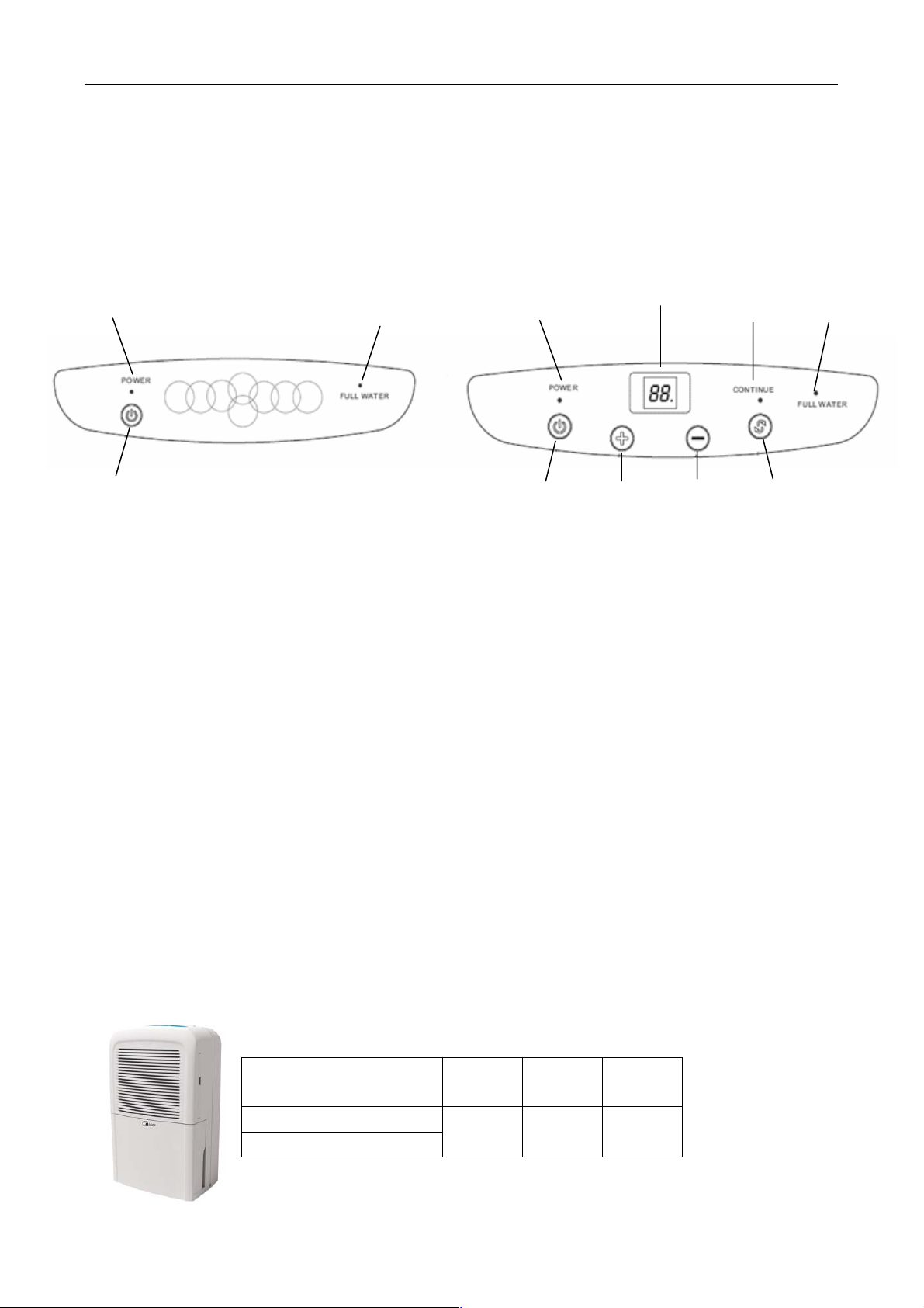
1.4 CONTROL LOCATIONS
2 3 2 8 4 3
1 1 5 6 7
1. ON/OFF Button: Power indicator links
slowly when the power is connected at the
socket (initial power).Press this button at this
time, the unit will directly go into
DEHUMIDIFYING operation with the original
factory humidity setting( 60%RH). Press the
button again, the unit will stop operation.
2 . POWER indicator: At the first time to
connect to the power, it flashes slowly The
POWER indicator lights after the unit is turned
on, and dark after the unit is turned off.
3. FULL WATER indicator: Lights up when the
bucket is full, and the unit stops operating
4.CONTINUE indicator: Lights up when the
unit is on CONTINUOUS DEHUMIDIFYING
range between 5℃~32℃.
LED display.
Humidity display and setting.
Self diagnose and defect display
5. HUMIDITY UP Button: When the unit is
operating, the setting humidity will go up by
pressing this button every time, the range of
justment is from 35%RH to 80% RH.
6. HUMIDITY DOWN Button: When the unit is
operating, the setting humidity will come down
by pressing this button every time, the range of
adjustment is from 80%RH to 35%RH.
7. CONTINUE Button: When the unit is
operational, press the Button will go into
CONTINUOUS DEHUMIDIFYING mode.
8. LED Digital display: This area will display the
room relative humidity under normal operation
and display the setting humidity when setting the
desired humidity.
mode.
1.5 OUTSIDE DIMENSIONS
Model Width
CE-CF0.3BD/N3-F
CE-CFZ0.3BD/N3-F
Height
(mm)
315 505 235
(mm)
Depth
(mm)
2
Page 4

GD Midea Refrigerant Equipment Co. Ltd Service manual for F Dehumidifier
2 Electronic function
2.1 When the unit is just powered on
When the unit is just powered on or the dropped
power is just restored, the unit will immediately
perform the self-diagnosis. The check items include
the water-full, temperature sensor and humidity
sensor. If there is no defect, the power indicator will
flash at 0.5Hz while all other indicators are off. All
buttons are invalid except the ON/OFF button.
2.2 Operating under setting humidity
When the ON/OFF button is pressed for the first
time after the unit is powered on or the power is just
restored from dropping, the unit will operate with a
original factory humidity 60%RH and the power
indicator will light. Under this condition, the humidity
can be set by pressing the Humidity Up/Down
buttons. When the indoor humidity is 5% higher than
the setting humidity, the compressor will be on.
When the indoor humidity is lower than the setting
humidity, the compressor will be off and the fan will
stop operating 3 minutes after the compressor is
shut down. If the indoor humidity is getting 5%
higher than the setting humidity, the fan will be on
immediately and the compressor will start too.
2.3 Continuous Dehumidifying mode
The compressor and the fan motor will always
be on and the Continue and power indicator will be
on. The LED will display the indoor humidity. Setting
humidity is not available.
2.4 Stop operation
When the unit is stopped operation by pressing
the ON/OFF button, the compressor and the fan will
shut down and all indicators will be off. The time for
defrost will be cleared. When the unit is restarted by
pressing the ON/OFF button, the unit will start with
previous set mode. Whether the defrost function
starts need to be prejudged. The self-diagnosis
function will just check the water-full defect. The fan
motor will work same as the compressor.
2.5 Compressor delay start
When the mode is changed but the compressor
does not start or the unit restart after stop workin g, if
the compressor accord with it’s starting condition,
the fan motor will start immediately while the
compressor will delay 3 seconds to re-start.
2.7 Protection and failure mode
2.7.1 Water full protection. When the water tank is
full , the compressor and fan motor will shut down
and the water full indicator will flash with LED
displaying P2. Under this situation, all button is out
of service. After the water is poured, the unit will
restore operating as previous setting.
2.7.2 Anti icing protection.
2.7.2.1 If the time accumulates up to 15 minutes
with compressor operating and the temperature of
o
evaporator lower than -1
C, the Anti-icing protection
function will be activated.
2.7.2.2 When the protection is activated, the
compressor will be off while the fan motor is on with
high speed, and the Turbo indicator will be on with
the LED displaying P1. The time will also be
cleared.
2.7.2.3 If the situation that compressor is off and fan
is on has lasted for 6 minutes or the ON/OFF button
is pressed, the unit will stop anti-icing protection
function.
2.7.2.4 After the Anti-icing function is completed, the
unit will restore operation as previous mode or stop
if the Anti-icing function is completed by pressed the
ON/OFF button.
2.7.3 Sensor failure check. When the output voltage
of sensor is lower than 0.5V or higher than 4.95V,
the unit will alarm and the LED displays E1 for
humidity sensor failure and E2 for temperature
sensor failure. Under this situation, the compressor
and the fan motor will shut down and the Power
indicator will flash at 5Hz. All buttons is out of
service. After the defect is cleared, the unit will not
work until the power to the unit is re-stored.
2.7.4 When the water full and sensor failure occur
together, the water full alarm has the priority on
display.
2.7.5 compressor protection: under all modes, the
compressor will delay 3 minutes to start after it stop.
3
Page 5

p
prop
p
p
3 TROUBLESHOOTING GUIDE
3.1 TROUBLESHOOTING GUIDE
In general, possible trouble is classified in three kinds. One is called Starting Failure which is caused from
an electrical defect, another is ineffective Air Conditioning caused by a defect in the refrigeration circuit and
improper application, and the other is called the Structure Damage.
ROOM AIRCONDITIONER VOLT AGE LIMITS:
NAMEPLATE RATING MINIMUM MAXIMUM
220~240V 198V 254V
3.1.1 Water level protection function abnormal
Abnormal water level protection function includes the following: (1) There is an alarm when the water
level is normal and (2) There is no alarm for full water.
Alarm at normal water
Water tank not
laced properly
Place water
tank carefully
Trouble in input circuit of water
level switch of drive board
components
Water level
switch broken
Replace
switch
Broken Main
chip of PCB
com
onents
Replace PCB
components
3.1.2 Automatic trouble alarm
When the pipe temperature sensor is defective, the motors of the compressor and the fan will be shut
down, and the power indicator will flash at 5 Hz.
Power indicator flashes at 5 Hz
The connector CN3 in
main PCB is loosed
Place it properly
Pipe temperature sensor trouble
No alarm at full water
Floating ball
of water tank
too heavy
Loosed input plug of
water level switch
Trouble in input circuit of water
level switch of drive board
Water level
switch broken
Broken main chip of
PCB components
Replace
switch
Replace pipe temperature sensor
Take out water tank
and remove water
Plug it again
erly
Replace PCB
com
onents
4
Page 6

GD Midea Refrigerant Equipment Co. Ltd Service manual for F Dehumidifier
3.1.3 Humidity sensor check
Humidity display is chaos
Water on the Humidity sensor
board
Dry it over heat
Humidity sensor board trouble
or main PCB defective
Replace humidity sensor
board trouble or main PCB
3.1.4 Fail to start or fail to start motor
3.1.5 Abnormal noise
5
Page 7

GD Midea Refrigerant Equipment Co. Ltd Service manual for F Dehumidifier
3.1.6 Complaint and remedy
Complaint Cause Remedy
No display on
panel or any one of
the button failure.
Fan motor w ill
not run.
Fan motor runs
intermittently
Fan motor
noise
Transformer
(Discharge transformer
before testing)
Display board or main
PCB failure
No power Check voltage at electrical outlet. Correct if none.
Power supply cord Check voltage at the power cord terminal on Main PCB.
Transformer
(Discharge transformer
before testing)
Wire disconnected or
connection loose
Main PCB failure Select fan speed and Check the voltage of P1, P2 on main
Capacitor (Discharge
capacitor before testing)
Will not rotate Fan blade hitting shroud or blower hitting scroll. Realign
Revolves on over
load.
Fan Replace the fan if cracked, out of balance, or partially
Blower Replace the blower if cracked, out of balance, or partially
Loose screws Tighten them.
Check resistance between the two input/output lines on
transformer. Replace the transformer if either of the input/output
is open or the transformer is damaged.
Replace the display board if it is +5V else replace the main
PCB.
Replace the power cord if none.
Check resistance between the two input/output lines on
transformer. Replace the transformer if either of the input/output
is open or the transformer is damaged.
Connect w ire. Refer to wiring diagram for terminal
identification. Loose. Repair or replace loss e terminal.
PCB. Replace the main PCB if no voltage.
Test capacitor . Replace if not within 10% of manufacture's
rating. replace if shorted, open or damaged
assembly. Check fan motor bearings. Replace the motor if motor
shaft don't rotate.
Check voltage. Call an electrician if not with in limits.
Test capacitor . Replace if not within 10% of manufacture's
rating. Replace if shorted, open or damaged.
Check bearings. Replace the motor if the fan blade can't
rotate freely.
Pay attention to any change from high speed to low speed.
Replace the motor if the speed does not change.
missing.
missing.
6
Page 8

GD Midea Refrigerant Equipment Co. Ltd Service manual for F Dehumidifier
Worn bearings Replace the motor if knocking sounds continue w hen
running or loose, or the motor hums or noise appears to be
internal while running.
Excessive
noise
Compress or
will not run while
fan motor runs
Insufficient
capacity
Stop instantly
after
startup.
The
compressor not to
stop even the room
humidity has got to
the setting value.
The unit starts
and s tops
Copper tubing Remove the cabinet and carefully rearrange tubing not to
contact cabinet, compress or, shroud and barrier.
Voltage Check voltage. Call an electrician if not within limits.
Wiring Check the w ire connections, if loose, repair or replace the
terminal. If wires are of f, refer to wiring diagram for identification,
and replace. Check w ire locations. If not per wiring diagram,
correct.
Main PCB failure Replace the main PCB if open.
Capacitor (Discharge
capacitor before testing)
Humidity sensor Replace if shorted, open, or damaged.
Compressor Check the compressor f or open circuit or ground. If open or
Air filter Clean or replace if restricted.
Condenser and
Evaporator
Fan motor Check the fan capacitor and replace if not within 10% of
Room structure Take proper measures to make the door and window s
Air flow Clean or remove if any barrier is found to block the
Less refrigerant Check the tubes for reasons of leakage. Recycle the
Capillary tube Regulate the flow if capillary tube and make the evaporating
Compress The inlet and outlet valve of the compressor is damag ed,
Refrigerant The amount of the refrigerant is too much, making the
Compressor The compressor is heat stuck. Replace after checking for the
Humidity sensor Check and replace if the Humidity sensor is open or
Main PCB Check and replace the main PCB
Power supply The input power supply voltage is too low . Call an electrician
Check the capacitor. Replace if not within 10% of
manufacturers rating. Replace if shorted, open, or damaged.
grounded, replace the compressor.
Clean or replace if restricted.
manufactures rating.
sealed w ell if gap is found.
inlet/outlet wind flow of the unit.
refrigerant, correct the leakage points and recharge.
temperature appropriate if the evaporator is frosted.
making the low pressure connected with the high pressure. The
refrigerating system is difficult to produce high pres sure and low
pressure. Replace the compressor after checking f or the reason.
compressor load too big. Recycle and recharge the refrigerant
after checking for the reason.
reason.
damaged.
if not within limits.
7
Page 9

GD Midea Refrigerant Equipment Co. Ltd Service manual for F Dehumidifier
frequently.
4 WIRING DIAGRAM
4.1 For models:
CE-CF0.3BD/N3-F
CE-CFZ0.3BD/N3-F
Humidity sensor Replace it.
Main PCB Check and replace the main PCB.
5 EXPLODED VIEWS
(See attached files)
6 SPECIFICATIONS
(See attached files)
8
 Loading...