

Page 1

Installation & User manual
ERHC1238S (120 cm)
ERHC938S (90 cm)
Canopy range hood
Page 2
Congratulations
Congratulations and thank you for choosing
our rangehood. We are sure you will find it a
pleasure to use.
Before you use the rangehood, we
recommend that you read t hrough the
relevant sections of this m anual, w hich
provides a description of your appliance and
it s funct ions.
To avoid the risks that are alw ays present
when you use an appliance, it is important
that the appliance is inst alled correctly and
that you read the safety inst ructions
carefully t o avoid m isuse and hazards.
We recommend that you keep this
instruct ion booklet for future reference and
pass it on to any fut ure ow ners.
After unpacking t he appliance, please check
it is not damaged. If in doubt, do not use the
appliance but contact your local custom er
care centre.
Conditions of use
This appliance is intended to be used in
household and similar applications such as :
• st aff kit ch en ar eas in sh o p s, o f f ices and
other working environments.
• f ar m h o u ses.
• by client s in h o t el s, m ot els an d o t h er
Contents
Important Safety instructions………..3
Description of rangehood……………..4
Components list…………………………….4
Technical specification………………….4
Rangehood dimensions…………………5
Installation…………………………………….5
Using your rangehood……………….…..9
Maintaining your rangehood…..…...10
Troubleshooting…………………………..11
Optional ducting accessories…….….12
Warranty……………………………………...13
TIPS & INFORMATION
IMPORTANT – CHECK FOR ANY DAMAGES OR
MARKS. If you find t he rangehood is damaged
or m arked, you m ust report it within 7 days if
you wish to claim for damage/ marks under
t h e m an u f act u r er ‟s w ar r an t y. Thi s d o es n o t
affect your statut ory rights.
ENVIRONMENTAL TIPS
INFORMATION ON DISPOSAL FOR USERS
• Mo st of t he p ac kin g m at er ials ar e r ecyclab l e.
Please dispose of t hose materials through
your local recycling depot or by placing t hem
in appropriate collection containers.
• If yo u wish t o discar d t h is p r o du c t , please
cont act your local aut horit ies and ask for t he
correct method of disposal.
Page 3
P a g e | 3
Accessible parts may become hot when used with cooking appliances.
Page 4
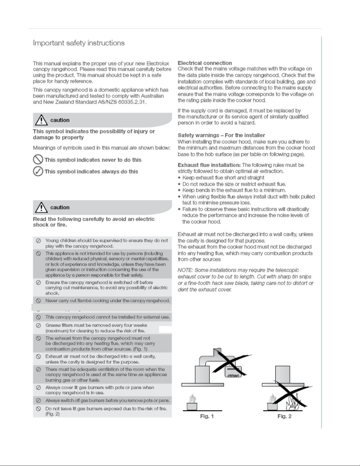
Components list
Model
ERCH1238S
(120 cm)
ERHC938S
(90 cm)
Main body and fan assemblies
2 fans
1 fan
Grease filters
4
3
Exhaust transition
2
1
Exhaust transition seal
2
1
Damper 2 1
Exhaust transition screws
8
4
ERHC938S
ERHC1238S
Additional items required for installation
Fixings required to attach rangehood
body and anti tilt points
Worm drive clamps, Duct tape or cable
ties
Ducting accessories
Product Description
Technical specification
Power supply: 240 Volts 50 Hz. Connects to 10A power point
Lights:
o 4 x 20 watt, 240 volts halogen (1200mm model)
o 3 x 20 watt, 240 volts halogen (900 mm model)
Page 5
P a g e | 5
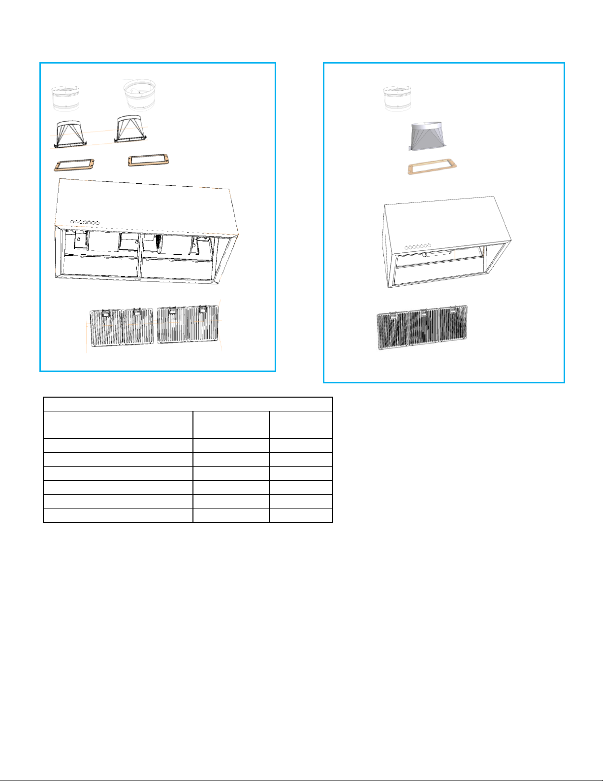
Model A B
C
ERHC938S
900
415
580
ERHC1238S
1200
415
580
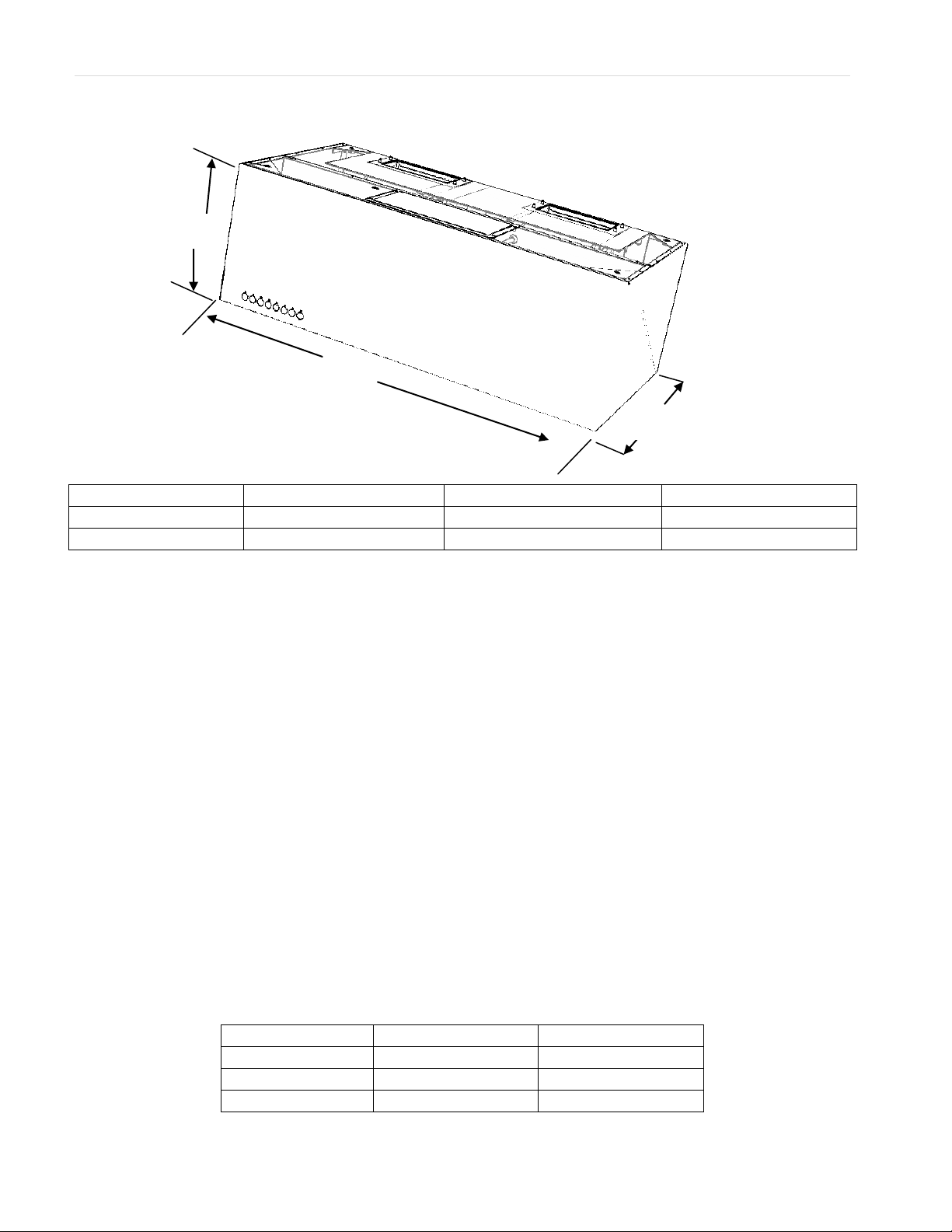
Cooker type
Minimum height*
Maximum height
Electric Hob
600 mm
1,200 mm
Gas Hob
650 mm
1,200 mm
Gas BBQ open grill
1,200 mm
1,200 mm
Rangehood Installation
1. Using a sprit level mark a vertical
centre line on the wall where the
hood is to be positioned, and a
horizontal line at the hood base
position.
NOTE: See table below for the minimum
and maximum height of the underside of
the hood.
2. Mark the location for the wall
mounting points and anti-tilt fixing
points as shown in (Fig. B).
3. Inst all suitable screws for
rangehood mounting points (to
support a t otal weight of 50kg)
to t he wall as marked (Fig. B).
Dimensions
B
A
C
* If t he inst ruct ions of the hob specify a greater dist ance than the minim um above, t hen that
shall be the minimum height for installation.
Page 6

Rangehood Installation (continued)
4. Prior to installing t he hood into position fix exhaust t ransition duct using screws
supplied, ensuring the seal is between t he rangehood top panel and the base of
the exhaust transition (Fig. C).
Transition pieces
1200mm model
Transition piece screw
holes (4 places)
Fig. C
Min.
Max
Top of
cooker
Mounting
points
Anti-tilt points
B
A
C
D1
D2
D3
D4
Fig. B
Warning: Failure to install the screws or fixing device in accordance with these instructions may
result in electrical hazards
!
Page 7

A B C
D1
D2
D3
D4
D5
D6
900mm model
366 mm
46 mm
500 mm
750mm
700 mm
650 mm
600 mm
787 mm
485 mm
1200mm model
366 mm
46 mm
900 mm
975 mm
925 mm
875 mm
825 mm
1085 mm
485 mm
If additional or alternative mounting points are required there 4 x M10 threaded mounting
points on the top of the hood as highlighted in the image below.
5. Mounting and securing the transition pieces is shown in Figure C.
! Important note: Pre-form ed holes must be used t o secure t ransit ion piece.
Fit ting screws in alternate locations may cause electrical safety risk.
6. Hang hood on the mount ing screw s, t ighten mounting screws t hen secure at the anti-tilt
locat ions as indicated in (Fig. B).
7. The canopy rangehood has been supplied w ith duct t ransit ion piece/ s, 200m m diam et er noncombustible flue pipe can be used with the transit ion piece/ s. Cont inue t he centre line to the
ceiling. Fit preferred flue pipe to the fan t ransition duct (Fig. D1 & D2).
Use w orm drive clamps, cable ties or suitable duct tape t o secure flexible pipe to the t ransit ion
duct .
NOTE: We recom mend ext ending flue pipe t hrough the roof to external roof cowl to vent
exhaust externally. We do not recom mend venting int o ceiling cavit y.
NOTE: To ensure optimum perform ance of the rangehood, t he use of rigid ducting is
recom mended.
The use of bends should be avoided. Rigid flexible duct ing is suitable, alt hough loose flexible
ducting is unacceptable. All duct ing must be fire ret ardant .
Electrical connection
Check that the inst allation com plies w it h the standards of local building, gas and electrical
authorit ies. Before connect ing t o t he mains supply ensure t hat t he mains volt age corresponds
to t he voltage on t he rat ing plate inside the rangehood.
D5
D6
Rangehood Installation (continued)
P a g e | 7
Page 8

Roof cowl
Flue (extension may be
required, depending on
installation)
Transition
Flue cover & flue cover
supports (optional
accessory, depending on
installation type)
Transition
90° Elbow
Flue (extension may be
required, depending on
installation)
Wall Vent
Front
Rear
Fig. D1
Fig. D2
Page 9

P a g e | 9
Using the Rangehood
Control operation
a. Lock
b. Speed 1 (minimum)
c. Speed 2
d. Speed 3
e. Speed 4 (maximum)
f. Timer off
g. Lamp
Lock – Press an d ho ld „lo ck‟ b u t t on f o r 3 se co n d s t o l o ck cont rol interface w hen
cleaning, press and hold for 3 seconds t o unlock cont rol interface
Speed 1– suitable for light frying and light barbecuing
Speed 2– suitable for frying, w ok cooking and barbecuing
Speed 3– suitable for int ensive frying, intensive wok cooking and barbecuing
Speed 4– suitable for very smoky cooking and/ or t o clear smoke from an area
that has a build up of sm oke
Timer off – At t he end of cooking if the t imer is activat ed, the rangehood will
cont inue to run for an addit ional 5 minutes to remove any odours t hat remain at
the com plet ion of cooking. During the 5 minute period t he fan speed w ill
gradually reduce unt il the canopy turns itself OFF.
When t he t im er fu n ct io n is act ivat ed t h e “ Tim er ” LED w ill illum in at e an d t h e
previously selected fan sped LED will turn off.
To deact ivate t he timer, press the t im er butt on again or press a fan speed button
to resume normal operation
Lamp – Press t h e „lam p ‟ sym bo l t o t ur n t he lam p s ON, The fir st p r e ss w i ll set t h e
lam ps to maximum intensit y. The second press will set the lamps t o half
intensity. The third press will turn the lam ps OFF.
a b c
d
e
f
g
ON
½ intensity
OFF
Page 10

Maintenance and cleaning
Caution
• Before maintenance or cleaning is carried out, the canopy rangehood should be
disconnected from the main power supply. Ensure that the rangehood is switched
off at the wall socket and the plug removed.
• External & internal surfaces are susceptible to scratches and abrasions, so please
follow the cleaning instructions to ensure the best possible result is achieved
without damage.
Stainless Steel Surface
Clean stainless steel surfaces using non-abrasive cleaning product s that are
specifically for use on st ainless st eel.
To ensure best result s also use an even pressure and follow t he grain of the stainless
steel. Use of a soft cloth reduces the risk of scrat ching. If the clot h is wet ensure t hat
a dry soft clot h is used to wipe down the surface again reducing t he risk of any
surface rust appearing.
Control panel surface
Use non-abrasive cleaning products
The control panel can be cleaned using warm soapy water.
Ensure the cloth is well wrung before cleaning. Use a dry soft clot h t o rem ove any
excess moisture left after cleaning.
Cleaning grease filters
The filters can be cleaned eit her by hand or in t he dishwasher. Aft er cleaning ensure
that the filters are complet ely dry before refitt ing.
By hand : Soak in warm water and some washing up liquid.
For st ubborn grease st ains use a soft nylon brush t o help remove t hese stains.
In a dishwasher : Ensure that placem ent of t he filters is made so as to not impede the
function of the dishwasher spray arm . Washing the filt ers in a dishwasher may cause
discolouration over time although it w ill not affect their performance. Filters should
be washed separately to crockery and kit chen utensils.
Inner panels and trough
After each use the inner panels and trough should be wiped clean with non-abrasive cleaning
products to prevent excessive build up of oils / grease.
Page 11

P a g e | 11
TROUBLESHOOTING GUIDE
Problem
Remedy
The cooker hood will not start
Check that cooker hood is connected to an electrical
supply
Check that a fan speed has been selected
The cooker hood is not working
Check that fan speed is high enough for the task
The grease filters are clean
The kitchen is adequately vented to allow entry of
fresh air
Check ducting and outlets are not blocked
The cooker hood has switched off during operation
The safety device may have tripped – turn off the hob
and wait for the device to reset. If the hood is
installed below the heights indicated in the
installation instructions the motor will cut out
frequently which will damage the hood
If you have completed all of the above checks and are still experiencing difficulty, please contact your local
Electrolux Service Centre
Changing the halogen lamps
Using a sm all flat blade screw driver rem ove t he inner stainless steel ring to
gain access to t he halogen globe.
When rem oving the inner ring, do so carefully, as t he glass lens could easily fall
out of the inner ring. Remove halogen globe, w hilst cool, and replace carefully
with a new globe.
The ERHC1238S rangehood has 4 x 20W, 12 volt halogen globes.
The ERHC938S rangehood has 3 x 20W, 12 volt halogen globes.
When handling globes hold with a clot h or gloves to ensure perspiration does
not come in contact w it h the globe as this can reduce the life of t he globe.
Trouble shooting
Page 12

NOTE: Accessories are to be purchased separately
Part number
Description
AR200RC
200mm Roof cowl
AR200F
200mm Flue (length = 1,200mm )
AR200WV
200mm Wall vent
AR200E
200mm 90° Elbow
AR200FD
200mm semi rigid flexible flue (0.7 m min & 3.0m max length )
AR200FJ
200mm Flue joiner
AR200WC
200mm worm drive clamp
AR209FS
Stainless flue cover to suit 900mm model
AR212FS
Stainless flue cover to suit 1200mm model
AR200RC
AR200F
AR200FD
AR200FJ
AR200E
AR200WV
AR200WC
Page 13

P a g e | 13
Page 14

 Loading...