

Page 1

Kochendwassergerät
Thermofix E, EL, GL
Water Heater
Chauffe-eau
«bouilloire»
Boiler voor
kokend water
Montage- und
Gebrauchsanweisung
Instructions for
installation and use
Instructions de mon
tage et mode d’emploi
Montage- en gebruiksaanwijzing
AEG
Page 2
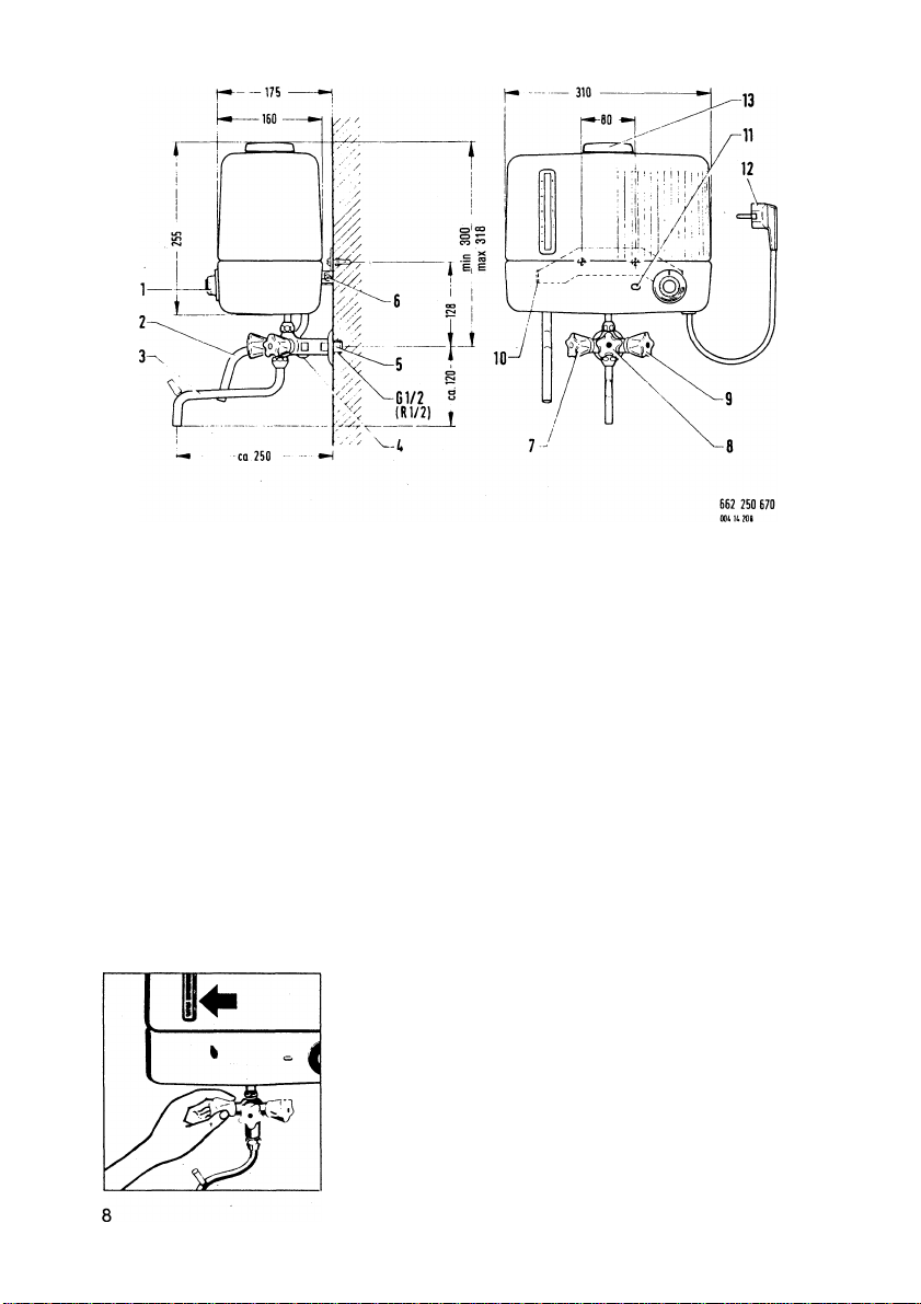
Temperature selection dial
1.
with pushbutton ON switch
2. Overflow pipe
Swivel spout 10. Wall mounting bracket
3.
4.
Flow control screw 11.
Cold water connection
5.
Wall mounting screw
6.
7. Tap handle, white (for filling)
Tap handle, red (hot water)
8.
Tap handle, blue (cold water)
9.
Indicating lamp
12. Connection lead (0.5 m long)
Cap
13.
1. Instructions for the user
1.1 Operating the appliance
Filling with water
Fill the container with the required amount of water
(from 0.5 to 5 litres) by turning the LH white tap handle.
The container Is provided with a scale which indicates
the amount of water filled.
Page 3
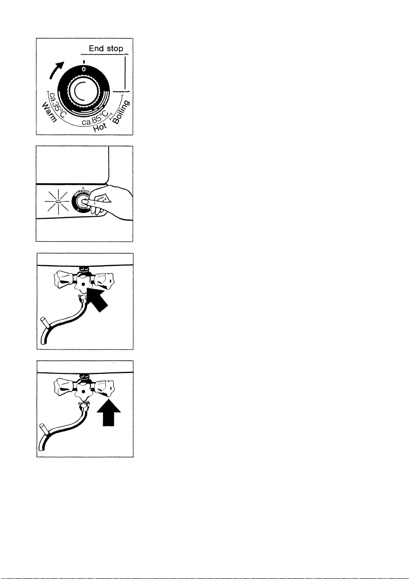
Setting the water temperature
Set the appliance to the desired water temperature by
turning the temperature selection dial:
The white range of the selection dial:
Warm to hot water from approx. 35 X to approx.
85 X
The red range of the selection dial:
Boiling water
(Continuous on model Thermofix E,
thermostatically controlled on models Thermofix
EL and GL - once the required temperature has
been, the fitted buzzer will operated).
Please note: The temperature selection dial cannot be
overwound!
Switching the appliance ON
Press the pushbutton which is located in the centre of
the selection dial. The indicating lamp will now light up
and the appliance will start to heat the water.
Switching the appliance OFF
If the appliance has been set to a temperature within the
white range of the selection dial, it will switch itself off
automatically once the set temperature has been rea
ched. _ - _
The appliance can be switched off at any time simply by
turning the temperature selection dial anticlockwise.
Caution: If the appliance has been set to continuous
boiling (Thermofix E), it is necessary to switch it off ma
nually.
With the thermostatically controlled boiling facility
(Thermofix EL, GL), the appliance will switch itself off
automatically when the boiling point has been reached
and will switch itself on again after the temperature has
droped. Here, too, the appliance must be switched off
manually.
To obtain warm or hot water
Turn the handle of the middle tap (marked red).
To obtain cold water
Turn the handle of the right-hand tap (marked blue)
Cold water can be obtained at any time, even whilst a fil
. xed by opening the red and blue taps simultaneously.
Important Note:
ling of water is heating up. Cold and hot water can be mi-
Installation and initial operation
Installation and initial operation of the water heater must be carried out by a suitably
qualified person who is responsible for ensuring that the work is done correctly and
who can explain to the user how the appliance must be operated.
The appliance must not be switched on when empty!
9
Page 4
The overflow pipe must not be closed or blocked, nor may it be extended by means of
flexible tubing or piping.
Caution: The water container, mixer valve, swivel spout and overflow pipe will
inevitably become hot (up to 100 °C) during use. Please therefore ensure that small
children are kept well out of reach of the appliance.
An additional safety device to prevent overheating is installed in this appliance, which
cuts out if there is a functional defect or the appliance is used improperly.
If the defect is still not rectified, the appliance absolutely must be inspected by an
electrician.
1.3 Care of your appliance
Wipe the appliance from time to time with a damp cloth and then rub dry. The
chromiumplated parts may also be cleaned with a suitable cleanser.
1.4 Maintenance of appliance
Decalcifying
Important: Regular decalcifying ensures troublefree
operation.
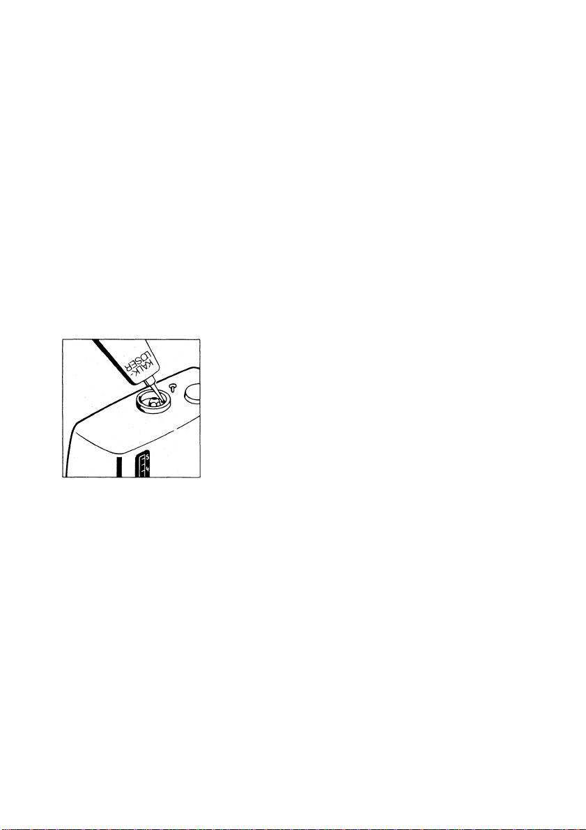
Use only liquid decalcifying agents, e.g. Cillit
décalcifier. Fill the appliance with 1 litre of water and
heat to approx. 50 °C (beginning of the second white
line on the temperature selection dial).
Remove the cap (13) and stopper from the top of the
container and pour in 50 - 100 ml of decalcifying agent
depending on the amount of furring. Replace the
stopper and cap and allow the decalcifying agent to
take effect for approx. 30 minutes. Then fill the container
to the 5 litre mark and reheat to 50 °C.
Leave the appliance for a further 30 minutes and then flush thoroughly with cold water,
making sure that the water can escape freely through the overflow pipe. Now empty the
appliance and re-flush with fresh water.
Caution! Concentrations of water-softener above the permitted level can damage or
even destroy the container seal!
Please do not use vinegar.
2. Important notes on installation
2.1 General
All AEi3 water heaters are manufactured and tested in accordance with pertinent VDE
regulations and DIN standards. They have been passed as safe in accordance with the
German laws on technical equipment and bear the interference suppression sym
bol, in compliance with DIN 44536 and also the 'splashproof symbol’. When instal
ling the appliance, please observe the technical data given on the nameplate as well as
the technical requirements of your local electricity and water boards.
10
Page 5
2.2 Technical features
The water heater is equipped with a 5 litre water container and a three-way mixing valve
which ist fitted with a G V2 A (R V2) connecting thread. The appliance may be used only as
an open, non-pressurized unit.
Thermofix E: Enamelled steel water container. Automatic switch-off in the „warr^“ and
„hot“ temperature ranges and continuous heating in the „boiling“ range.
Thermofix EL: Enamelled steel water container. Automatic switch-off in the „warm“ and
„hot“ temperature ranges. In the „boiling“ range the appliance switches itself off auto
matically and switches itself on again when the temperature drops below boiling point.
Thermofix GL: Glass water container, temperature control as on Thermofix EL.
2.3 Installing the appliance
The water heater should be installed only in a room which is free from frost. If the ap
pliance is nevertheless exposed to frost, make sure that it is completely emptied.
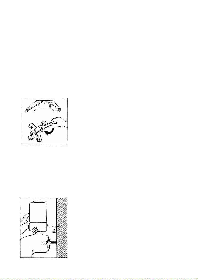
Securing the wall mounting bracket
Using the mounting template supplied, mark the posi
tions of the screwholes for fixing the wall mounting
bracket. Now fix the bracket to the wall by means of wall
plugs and suitable woodscrews, making sure that the
bracket is perfectly horizontal. The oblong holes permit
lateral and vertical adjustment.
Important! If the water heater is to replace an applian
ce of another make, you can use a universal wall su
spension bracket which is available as an accessory (EN0. 612 899 300, illustration on page 14). If this wall
suspension bracket is used, there will be need to drill
new mounting holes.
Fitting the three-way mixing valve
The mixing valve Is fitted with a DIN ISO 288 G V2 A thread for connection to the water
supply.
The thread must be properly wound with hemp or silicon sealing tape. Slide the cover
plate over the water pipe and then, using a suitable open-ended wrench, screw the mi
xing valve into the water pipe. With the last turn align the mixing valve in such a way that
the flow control screw is pointing downwards. Attach the swivel spout to the underside
of the mixing valve by means of the cap nut.
Fitting the water container
Push the cap nut of the pinch-type fitting, together with
the washer and the expanding seal, onto the inlet and
outlet tube of the water container.
Attach the inlet and outlet tubes of the appliance to the
mixing valve, at the same time guiding the screws of the
rear angle bracket into the oblong holes of the wall
mounting bracket.
The wall clearance and the vertical position of the ap
pliance can be adjusted by means of the oblong holes.
Once adjustment has been made, tighten the screws of
the wall mounting bracket and the cap nut of the pinchtype fitting. -j-j
Page 6
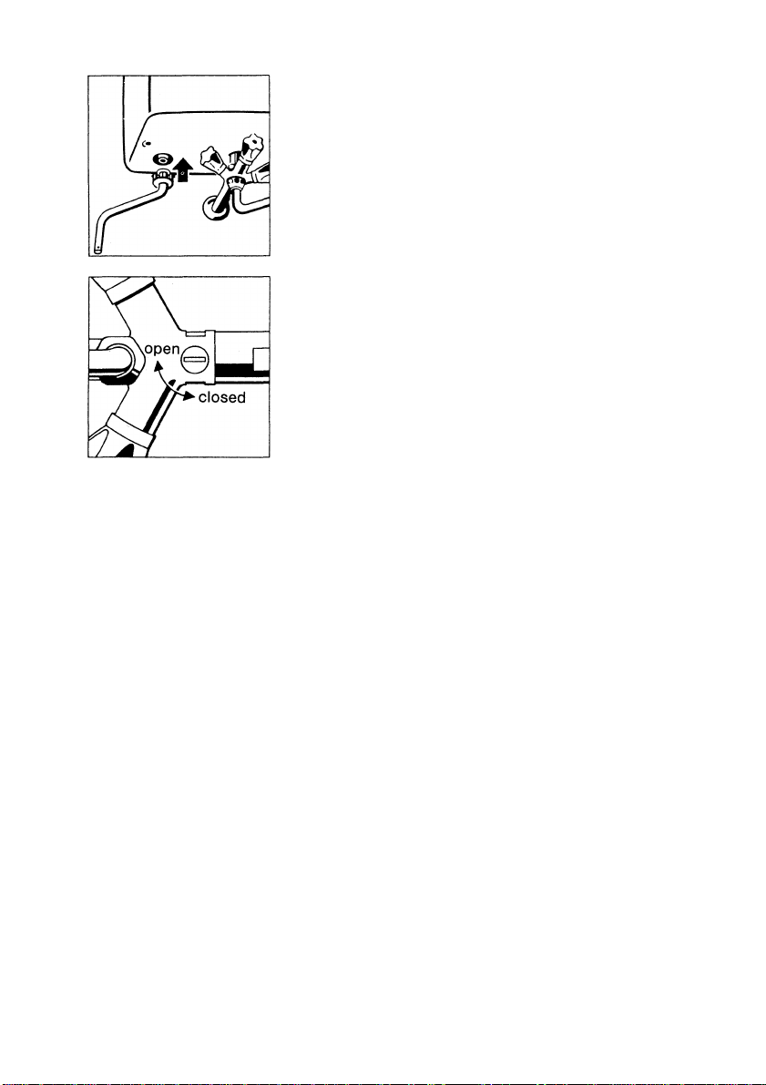
Fitting the overflow pipe
Slide the fixing bush over the end of the overflow pipe.
Push the overflow pipe onto the outlet pipe which pro
trudes from the appliance housing and secure by pres
sing in the retaining rings.
Setting the flow control screw
In cases where the water pressure Is extremely high, the
inlet flow of the cold water can be reduced by means of
the flow control screw. Turn the screw In the direction
marked „closed“.
The cold water supply can be shut off completely by set
ting the slot of the flow control screw exactly at right
angles to the direction of flow. Maximum flow rate is ob
tained by setting the slot of the flow control screw in line
with the direction of flow.
In order to clean the flow control valve, turn the screw
through an angle of 180 ° and flush thoroughly.
2.5 Electrical conriection
The electrical connection must not be carried out until the appliance has been proper
ly connected to the water supply.
When effecting the electical connection pay particular attention to the requirements of
your local electricity supply authority and any other generally applicable regulations (in
Germany: VDE 0100).
The water heater is supplied with a connection lead of a length of approx. 0.5 m which is
fitted with an earthed safety plug. It ist advisable to provide the applicae with a separate
electrical circuit.
2.6 Initial operation and control
Initial operation of the water heater must be carried out by a suitably qualified person
who is responsible for ensuring that the work is done correctly and who can explain to
the user how the appliance must be operated.
Correct operation should be ascertained during initial operation.
Important: Possible dirt and residues resulting from installation should be removed
prior to initial operation by flushing the appliance thoroughly. Then fill the appliance
with water, bring it to the boil and then flush it a second time.
After installing the appliance please hand this instruction manual to the user!
12
Page 7
3. After-sales service
Complaints which arise through failure to observe these instructions cannot be
acknowledged!
Any faults which are not mentioned in this instruction manual must be referred to our af
ter-sales service department.
The list of addresses can be obtained from the guarantee conditions which accompa
ny the unit.
It is essential that you state the model designation and the E-Number given on the na
meplate in order to avoid unnecessary queries.
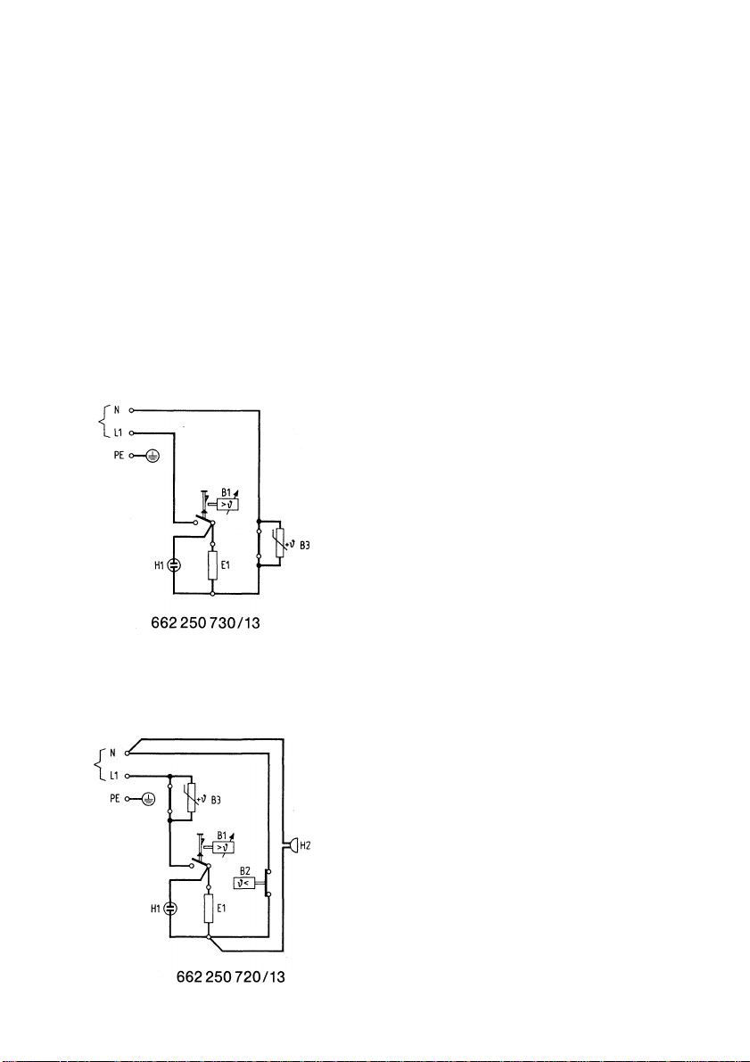
Wiring diagram for Thermofix E
Q = ON button for B 1
H1 = Indicating lamp,
H 2 = Buzzer
E = Heating element
X = Terminal board - 2-pole - inside appliance
B1 = Temperature selection limiter
B2 = Steam regulator
B3 = Temperature control
Wiring diagram for Thermofix ELyGL
13
Page 8
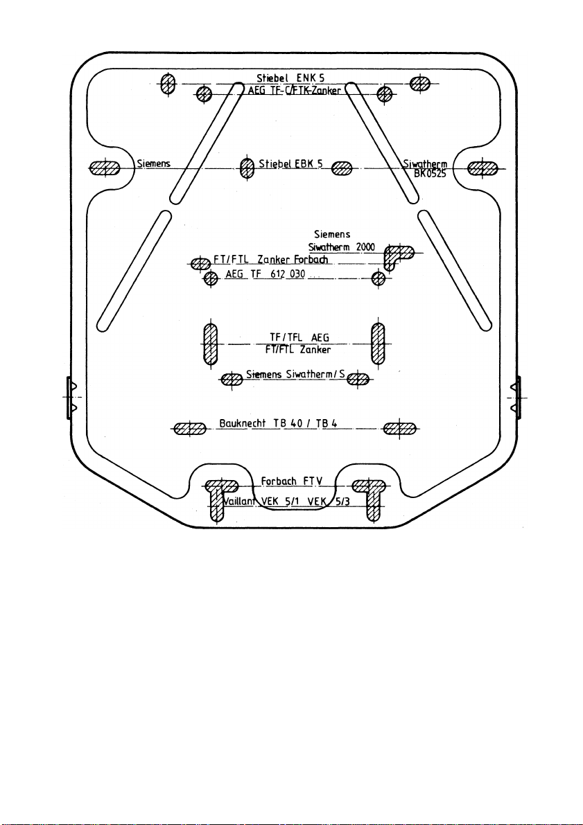
Universal-Wandaufhangung
Universal wall bracket
14
 Loading...