

Page 1
INSTRUCTIONS
FOR
INSTALLATION
USE AND
MAINTENANCE
FOR COOKING
- GB -
Page 2
F
Fig. 2
1/2"
HOSE ATTACHMENT
A=
FOR LIQUID GAS
FLEXIBLE PIPE
T=
C
G
F
Fig. 3
BACK SIDE
HOSE ATTACHMENT
B=
FOR NATURAL GAS
(AND TOWN GAS
EXTRA E.E.C.
COUNTRY ONLY)
T=
FLEXIBLE PIPE
Flexible
tube
entry
Fig. 13
Fig. 15
1
8
1
2
3
4
8
7
5
6
2
7
3
6
4
5
Fig. 14
G
A
Fig. 16
Fig. 4
BACK SIDE
B
Fig. 5B
3
4
2
Fig. 7
BARS
Inflexible
tube
entry
170
Fig. 8
A
Fig. 5A
Fig. 6
NO NO YES
T
Z
Fig. 17
230 V ~
L1
N
E
E = GREEN and Yellow / N = BLUE / L1-L2-L3 = BROWN
400 V 2N~ 400 V 3N~
L1
1
2
L2
3
4
N
5
E
L1
1
L2
2
L3
3
4
N
5
Fig. 17B
BURNER PAN
FAST 12÷18 cm
SEMI FAST
18÷24 cm
Fig. 19
Fig. 17A
1
2
3
4
5
Max
E
Off
Low
Fig. 18
A
Fig. 20
Max
Fig. 9
Fig. 11
Low
Off
Fig. 10
Fig. 12
1
2
3
4
5
Fig. 21
V
B
F
8
7
6
Fig. 22
P
S
Fig. 23
2
Fig. 24
Page 3
Getting to know your new cooker
Thank you for choosing one of our products.
Our cookers are of simple, rational design. They are constructed to the best
standards to ensure good service and outstanding safety.
Please read this manual carefully; it will provide all the advice needed to allow
you to obtain the best results from the very first day.
These instructions for use are divided into two sections:
1st section: for the qualified technician
2nd section: for the user
1ST SECTION
FOR THE QUALIFIED TECHNICIAN
INSTALLATION
IMPORTANT: The gas and electricity connections and any adjustments must
be made by skilled staff. The manufacturer refuses all liability for
damage of any kind resulting from failure to comply with current
regulations or negligent installation of the appliance.
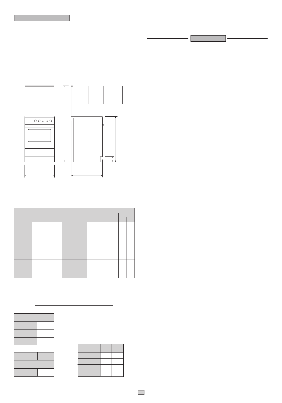
Fig. 1
OVERALL DIMENSIONS
MODEL WIDTH (X)
51 480
52 495
1320
845
X
500
100
TECHNICAL DATA: GAS PART
CHART 1
GAS TYPE
NATURAL
GAS
BUTANE GAS
L.P.G. GAS
PROPANE GAS
TOWN
GAS
OPERATING
PRESSURE
mbar
20
28
30
37
8
NOZZLE
Ø
DESIGNATION
Nº
FAST
135
SEMI-FAST
95
OVEN THERMOSTAT
130
OVEN THERMOMETER
135
105
GRILL
FAST
85
SEMI-FAST
62
OVEN THERMOSTAT
80
OVEN THERMOMETER
85
70
GRILL
265
FAST
170
SEMI-FAST
250
OVEN THERMOSTAT
255
OVEN THERMOMETER
210
GRILL
BURNER
POWER
kW
Max. Min.
0,62
3,09
0,32
1,56
3,00
3,00
1,90
0,62
3,09
0,32
1,56
3,00
3,00
1,90
0,62
3,09
0,32
1,56
3,00
3,00
1,90
FLOW RATE
l/h g/h
Max Min. Max Min.
59
295
30
149
286
286
181
703
355
682
682
432
141
73
225
114
219
219
138
Values for town gas injectors are valid for extra european country only.
TECHNICAL DATA: ELECTRICAL PART
CHART 2
CONVENTIONAL
OVEN
UPPER
ELEMENT
LOWER
ELEMENT
GRILL
ELEMENT
GAS
OVEN
NB.
When gas grill is not fitted
GRILL
ELEMENT
Watt
550
1400
550 +
1400
Watt
1400
CHART 3
ELECTRIC
HOT PLATES
RAPID
STANDARD
RAPID
STANDARD
ø
mm
145
145
180
180
Watt
1500
1000
2000
1500
N.B.: The fast electric hot plates are marked with a red dot.
1) INSTALLING THE COOKER
After removing the external packaging and the internal packaging of the various
moving parts, position the cooker ensuring that the installation area is normally
ventilated without any drafts which might blow out the burners. To ensure perfect
presentation, the stainless steel parts are mounted on the appliance protected
by a plastic covering, which must be removed before using the appliance.
N.B.: The sides of adjoing kitchen units in contact with the cooker must be capable
of withstanding temperatures of approximately 90°C. It is essential that furniture
in contact with the cooker are heat resistant or protected by a similar material.
If the adjacent cabinet top is higher than the cooker hob, a 20 mm, clearance
should be kept between the furniture unless lined with a suitable fireproof material
the clearance above the cooker hot should be at least of 630 mm.
GAS APPLIANCES
This appliance is not connected to a device to vent the combustion products. It must
therefore be installed and connected in conformity with the installation standards in
force. Particular attention must be paid to the standards on ventilation of the room.
1a) VENTILATION OF ROOMS
Remember that this appliance can be installed and work in well-ventilated rooms only,
according to the standards in force, such as to allow, with openings on the external
walls or with special ducts, a correct natural or forced ventilation ensuring permanently
and sufficiently both the entry of the air needed for correct combustion and the removal
of spent air. In particular when there is only this gas appliance in the room, there must
be a hood over the appliance to ensure the natural and direct removal of spent air,
with a vertical straight duct of length equal to at least twice the diameter and a minimum
section of at least 100 cm
must be a similar 100 cm
2
. For the indispensable entry of fresh air into the room there
2
(5,16 cm2 x kW) opening directly to theoutside, situated
at a height near floor level so that it is not blocked either inside or outside the wall and
so as not to cause disturbances to correct burners combustion and to the regular
removal of spent air and with a difference of height with respect to the outlet opening
of at least 180 cm. Remember that the quantity of air necessary for combustion must
never be less than 2m
3
/h for each kW of power (see total power in kW on the appliance
data plate).
In all other cases, i.e. when there are other gas appliances in the same room, or when
43
23
natural direct ventilation is not possible and natural indirect or forced ventilation must
be installed, contact a qualified specialist who will install and make the ventilation
system, scrupulously observing the regulations contained in the standards in force.
The openings must be so positioned that there are no draughts of air which cannot
be tolerated by the occupants.
2) GAS CONNECTIONS
The installation must be in accordance with regulations set by the local gas Authority.
This appliance belongs to class "1" against fire dangers (see N.B.). Between the cooker
and gas supply line is required a gas shut off valve (easy of access) to be kept closed
when the cooker is not in use. The pressure regulators for Lpg must be in accordance
with the requirements.
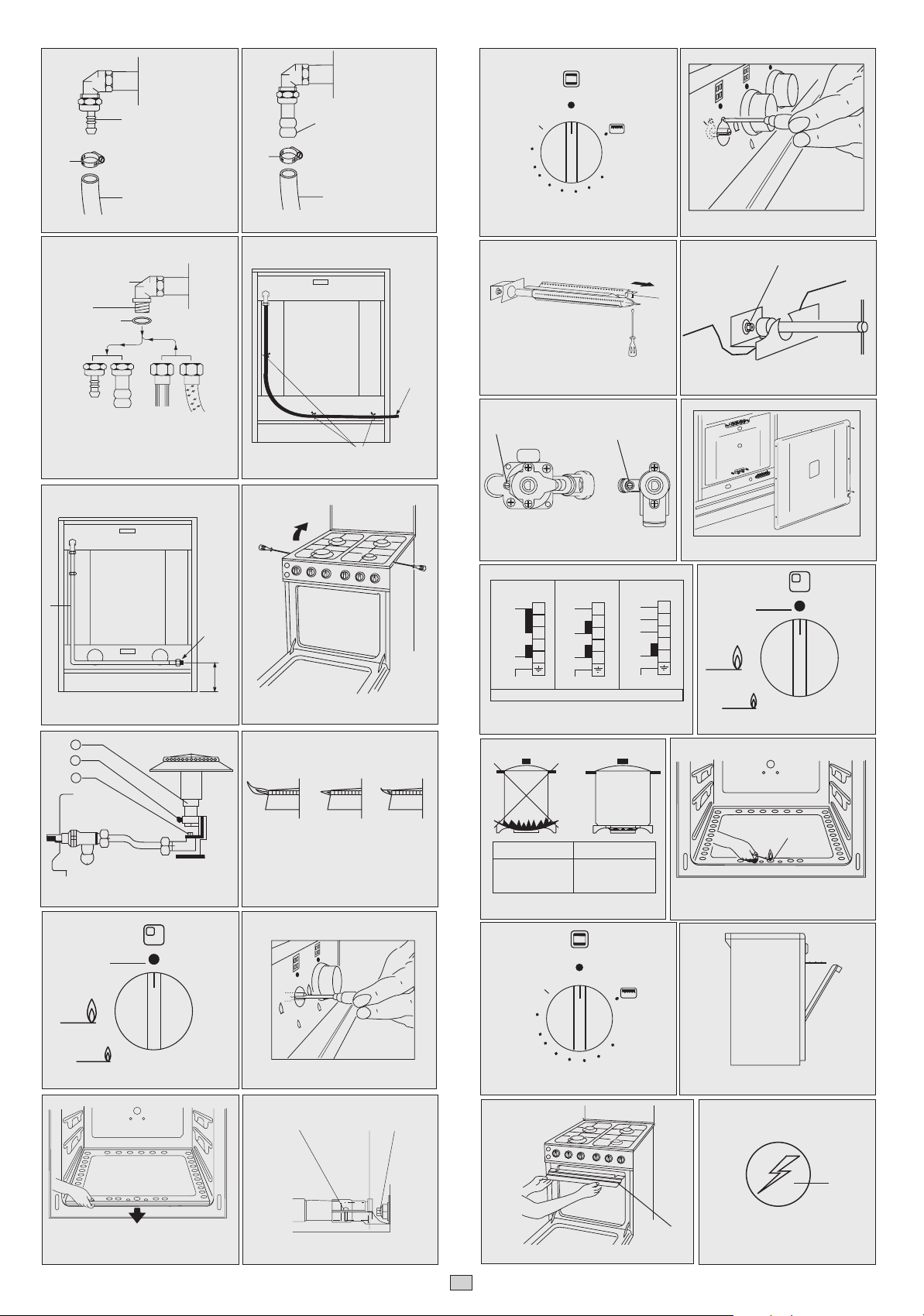
2a) CONNECTION TO GAS CYLINDER
Cooker working with Lpg gas can be connected with a flexible pipe (T ø 8 mm) fixed
to inlet connector A (fig. 2). The pipe must always comply with the regulations in force
in the country where the appliance is installed. Both ends must always be secured by
means of a hose clamp F (fig. 2).
2b) COOKER SET FOR NATURAL GAS AND (TOWN GAS EXTRA E.E.C. COUNTRY)
The flexible pipe (T ø 13 mm) must comply with the rules in force in the country in
question. The pipe must be fixed to the inlet connector B (fig. 3) and to the main gas
tap. Both end be secured with hose clamp F (fig. 3).
WARNING
The flexible pipe must never reach, in any point a temperature higher than 50°C above
the ambient temperature. Do not submit it to torsion or tension efforts. It must not
present strangling or sharp bent. It is advisable to replace it periodically.
Pipe connection
Make the connection using an iron (R) or copper pipe (S) starting from attachment
3
Page 4

C in (fig. 4). Remove hose attachment B using a 23 mm spanner. When making
the connection include an accessible ensure that the seal G is always placed
between the hose attachment and union C (fig. 4). When the connection is complete,
always check that there are no gas leaks from the union.
N.B. The connection between the end of the gas train and the supply can be made
on the right so that the gas pipe does not have to pass behind the cooker. In case
of connection on the left please relate to what already described in paragraph gas
connection having care to let the flexible tube pass through a holder see (fig. 5A)
in case of inflexible connection, see (fig. 5B).
3) ELECTRICAL CONNECTION
The appliance belong to class "X" against fire dangers (see N.B par. 1).
Connection of the appliance to the power mains should be done by a licensed
electrician familiar with local safety regulations.
- This appliance must be earthed by law.
- Before connecting the appliance to the electrical supply, check that the
earth system in your house is working correctly.
- Check that unit voltage and power, marked on the rating plate applied on the
appliance, are correct for the supply;
- It is necessary that the feeding network is protected by a powerful switch able
to disconnect completely the network with a contacts separation of at least 3
mm.
Be sure that the earth wire green/yellow is not interrupted by the switch.
Important: The wires in the mains lead are so coloured:
- green/yellow = earth “ ”
- blue = neutral “N”
- brown = live “L”
- The supply cable must not come into contact with any component the temperature
of which exceeds the ambient temperature by 50°C;
- If a plug is used for connection, the plug to be connected to the supply cable
and the socket to which it is connected must be of the same type (conforming
to the standards).
- Easy access to the plug or the switch is ensured once the appliance is installed;
- Ensure that there is sufficient cable allowed for any subsequent removal of the
unit.
The manufacturer declines all responsibility for any damage to persons or
things caused by failure to observe the rules indicated above.
4) CONVERSION FOR DIFFERENT TYPES OF GAS
The cooker carries a label specifying the type of gas for which it has been preset.
If it is to be used with a different type of gas, convert as follows with:
— Replacement of the hose attachment as in the previous section "Gas connection"
— Replacement of the nozzles and air adjustment.
When using liquid gas this screw must be fully tightened.
After making this adjustment check that the burner remains on when switched
rapidly from full on to minimum position and viceversa.
4c) Gas grill Burner
The figure 15 represent the gas grill burner
The nozzle is replaced as described below:
— Open the oven door.
— Unscrew the screw A which fasten the grill burner to the oven ceiling
and estract the burner from the oven (fig. 15)
— Introduce in the nozzle-holder a 10 mm socket spanner and remove the nozzle G (fig. 16) replacing
it with the new one suitable for the new gas type (see Chart 1)
— Once executed such operation reset the burner and check that it remains on.
In case of problem, move the burner back or before placing it in position for
to get a correct combustion and a good regulation of the air.
— Minimum setting
Since the grill burner always operates at full flame, there is no need to regulate
the minimum setting.
— Important
Once the procedure for adapting the cooker to one type of gas or another
is complete, we strongly advise staff to check using soapy water that
there are no leaks from the unions used to make the conversion.
4d) Burners with safety valve
The procedure for regulating the minimum flame on cookers with safety valves
on the hob burners, oven and grill burners is as described in paragraphs 4a,
4b and 4c. However, in this case the minimum setting screw Tor Z is on the
left of the rod of the gas tap or the thermostat (fig. 17).
TRANSFORMATION OF ELECTRIC FEED TYPE
Some cookers, even if manufactured for working at 230V~, can be feeded with
threephases systems. For their transformation you have to disconnect current,
remove the back side of the cooker (fig. 17A) and settle the movable connectars
in terminals block (see fig. 17B)
Chart 4
Type of
cooker
Full gas
Full gas with elect. grill
Full gas with 1 elect. plate
Full gas with el. oven
1 electric plate
Single phase connections 230V~
Main cable Features
Caoutchout H05 RR-F
Caoutchout H05 RR-F
Caoutchout H05 RR-F
Caoutchout H05 RR-F
3 x 0,75 mm
3 x 1 mm
3 x 1 mm
3 x 1,5 mm
2
2
2
2
4a) Hob
The nozzles are replaced as described below:
— Disconnect the electricity supply plug if present and close the gas tap installed
upstream of the appliance.
— Remove the hob pan stands, flame caps and burner cups.
— With a screwdriver remove the two screws locking the hob, raise it up and
secure it to prevent from falling back down (see fig. 6)
— Remove the nozzle (2 fig. 7) and screw on the new one suitable for the new
gas type (see chart 1).
— Regulate the flame by backing off the screw (4 fig. 7). Raise or lower the pipe
(3 fig. 7). The best flame conditions are shown in (fig. 8) (regulate with burners
hot if possible).
— Reassemble all components, following the above sequence in reverse order.
— Low flame setting (olso for oven with thermometer)
To obtain this, set the knob in the position where the gas tap opening is
minimum (this position is indicated by a small flame screen-printed on to the
fascia in fig. 9). Slide the knob off and adjust the inside screw coaxial with the
rod of the gas tap (hole in the centre of the knob mounting rod, fig. 10).
Tighten or back off the screw until the flame is brought down to the level
required. This adjustment must be made with the burner on.
When using liquid gas this screw must be fully tightened. After making
this adjustment check that the burner remains on when switched rapidly from
full heat to minimum position and viceversa.
4b) Gas oven burner
— Remove the oven bottom (fig. 11).
— Unscrew the screws V (fig. 12) and remove the upper collar fixing the air muff
fig. 12) in order to have easier access to the nozzle.
B (
— Remove the nozzle (F fig. 12) and screw on the one which is suitable for the
new type of gas (see chart 1).
— Regulate the flame by backing off the screws (V fig. 12) and move the pipe
(B fig. 12) backwards or forwards.
— Regulating the thermostat low flame position.
To do this, turn the oven to full heat (8) for about 10 minutes, then bring the
knob back to the minimum setting, position 1 (fig. 13). Remove the knob and
use the screw on the body of the thermostat (fig. 14) to set the flame size.
Type of
cooker
4 el. plates and elect. oven
Features
Keeping in consideration the simultainety coefficient of 0,75.
Single phase
connection
230 V~
Caoutchout H05 RR-F
3 x 4 mm2 4 x 2,5 mm2 5 x 1,5 mm
Three phases
connection
400V 2N~
230V 3~
Caoutchout H05 RR-F Caoutchout H05 RR-F
Three phases
connection
400V 3N~
2
FACIA PANELS
The below facia panels and hobs present the most of our productions.
For further information please consult this booklet following paragraphs.
FACIA PANELS DESCRIPTIONS
1) Knob for burner A and for electric plate A
2) Knob for burner B and for electric plate E-B
3) Knob for burner C and electric plate C
4) Knob for burner D and electric plate D
5) Knob for gas oven or electric oven
6) Knob for Timer (Optional)
7) Ignition button (Optional)
8) Oven light button (Optional)
9) Grill/turnspit button (Optional)
10) Warning light for electric plates.
4
Page 5

ENAMELLED FACIA PANELS
9 3462 51 78
2 10 1 5 3746
If the appliance is supplied with it, the functioning of the heating element is
highlighted by the illumination of the oven light, otherwise it will be indicated
by a warning light placed on the facia-panel.
6a) Lighting the burner manually
Open the oven door and place a lighted match against the hole in the centre
of the oven bottom A (fig. 20). Turn the oven knob anticlockwise until the
pointer reaches (8) (full heat) (Fig. 21). Look at the holes in the oven bottom
to check that the burner has ignited, close the door and position the knob as
required (Chart B). To switch the burner off turn the knob clockwise until the
pointer is vertical on ( ) (fig. 21).
CHART B
9342 51 7 8
Knob Position
1 140 °C
2 150 °C
3 160 °C
4 170 °C
5 190 °C
6 210 °C
7 230 °C
8 250 °C
Temperature °C
OVEN WITH THERMOMETER
The oven knob is of the same model of the ones of the hob's burners (fig. 18).
The thermometer, situated on the oven door, signals the temperature of the oven.
Only the utilisation will consent you to find a perfect regulation of the knob, in order
to obtain the temperature required.
BC
DA
EC
DA
BC
DA
C
DA
2nd Section
USE
WARNING:
Children should be kept away while the oven or grill (gas or electric) is
in use since accessible parts become hot.
- Do not use oven base panel as a shelf, make use of the oven shelves.
- To avoid splattering and smoke, position collecting tray under the turnspit with
some water in it.
- Never close the drop down tempered glass lid when burners or electric hot-
plates are on or they are still hot, wait until they cool down and then close lid.
- Always turn pan handles to the side or to the back of the hob. If they are left
out intothe room they can easily be hit or reached by children, this knocking
the pan off the hob.
- Don't let children sit down or play with the oven door. Do not use the drop
down door as a stool to reach above cabinets.
- Once your cooking is oven make sure to close the main gas supply.
The gas taps are fitted with a safety device prevent them from being opened
accidentally
5) GAS HOB
5a) Lighting burners manually
Open the gas tap on the metre or the gas cylinder, light a match and place
it against the burner to be lit. Then press the relative knob and turn it
anticlockwise until the flame setting required is reached (fig. 18). Over each
knob, the fascia panel is screen-printed with a diagram indicating the relative
burner. To turn off the burner turn the knob clockwise to ( ) (fig. 18).
The minimum position is at the end anti-clockwise rotation of the knob. All
operation positions must be chosen between the positions of max. and min.,
never choose them between max. and off.
5b) Using hob burners
The hob consists of burners of different sizes.
To ensure optimum efficiency in use of gas, with minimum consumption, follow
the hints given below:
— Each burner must be used with a suitably sized pan (fig. 19) so that the
flames do not project beyond the pan bottom.
— Once the contents are boiling, turn the knob down to minimum (low flame
fig. 18).
— Always put the lid on the pan.
6) GAS OVEN
For reasons concerning safety and regulations in force, the simultaneous use
of the gas oven burner together with electrical:gas grill is forbidden (EEC
normes). In case of gas oven with gas grill, see knob with double selection
fig. 21. In case of gas oven with electrical grill, the gas oven burner cannot
be switched on by pushing the grill button (fig. 31) and if it is in function it will
turn off.
150
MIN
200
250
MAX
6b) Using the gas oven
The first time the oven is used, allow it to heat up for about 30 minutes at
full heat, in order to eliminate any smells or fumes produced by internal
components. To start cooking, turn the pointer of the knob in (fig. 21) to the
temperature required (chart B). Wait at least 15 minutes before placing the
food inside, to cooking times.
CHART C
Food
MEAT PASTRY
ROASTED PORK 185-210 FRUIT CAKE 220
ROASTED BEEF 250 MARGHERITA CAKE 190
ROASTED VEAL 220 BRIOCHES 175
ROASTED LAMB 220 SCONES 235
ROASTED HARE 230 RING-SHAPED CAKE 190
ROASTED RABBIT 235 PUFF-PASTE 200
ROASTED TURKEY 220 GRAPES CAKE 200
ROASTED GOOSE 235 STRUDEL 180
ROASTED DUCK 225 SAVOIA BISCUIT 290
ROASTED CHICKEN 235 APPLE FRITTER 200
ROAST-BEEF 200-225 PUDDING 200
FISH 200-225 TOAST 250
Temperature °C
Food
BREAD 230
Temperature °C
7) GAS GRILL
7a) Lighting the burner manually
To light the grill, simply open the oven door fully, turn the knob clockwise until the
pointer is against the symbol (fig. 21)
and place a lighted match against the grill burner. To switch the burner off turn
the knob anticlockwise until the pointer is vertical on “ ” (fig. 21).
7b) Using the gas grill
After ignition, wait for 5 minutes before placing the food under the grill and leave
the oven door half opened as shown in (fig. 22). To prevent the knobs and gas
taps from overheating, the guard (canopy) S (fig. 23) must be fitted.
Electrical ignition for hob burners (optional)
Follow the initial procedure as described in paragraphs 5a.
In this case no match is required; simple keep button‚ on the facia panels pressed
(fig. 24) to ignite the burner.
8) APPLIANCES WITH SAFETY VALVE
To light the burners proceed as described in the precedent paragraphs.
However, in this case, once the knobs have been turned on they must be pressed
for 10 seconds to heat the thermocouple bulb (fig. 25). If the burner flame goes
out for any reason, the safety valve will automatically intervene and cut off the gas
flow to the burner concerned.
Example of hob burner with thermocouple (T) and electric ignition (C) (
fig. 26).
9) ELECTRIC HOT-PLATES
When an electric hot-plate is used for the first time or after it has been out
of service for a long period, operate on setting 1 for about 20 minutes to
eliminate any moisture from the internal insulating material.
5
Page 6

— Use pans with a thick, flat bottom (fig. 27).
— Never use pans with diameter smaller than that of the hot-plate itself.
— Dry the bottom of the pan before placing it on the hot-plate.
— Do not switch on the power until the pan has been placed on the hot-plate.
— For good maintenance, after use wipe the hot-plate over with a rag dipped
in oil, so that its surface is always clean and shining. This will prevent rusting.
— The hot-plates are independently controlled by a 7-position switch activated
by turning the knob clockwise to the position required (fig. 28).
Over each knob, the fascia panel is screen-printed with a diagram indicating
the relative hot-plate R (fig. 28). A red indicator light shows that one or more
hot-plates are in operation.
— For purely guideline purposes Chart D shows settings. The power values
corresponding to the various knob positions are shown in Chart E.
CHART D
CHART E
Type of electric plates No. position 1 2 3 4 5 6
Ø145 Standard 1000W 6 + 0 100 165 250 500 750 1000
Ø145 Rapid 1500W 6 + 0 135 180 250 625 875 1500
Ø180 Standard 1500W 6 + 0 135 220 300 850 1150 1500
Ø180 Rapid 2000W 6 + 0 175 220 300 850 1150 2000
Rapide
Electric
Plates
Heat
Power
0 Off
1 Slight
2 Mild
3 Slow
4 Medium
5 High
6 Max
Power heating of the electric plates
To melt butter, chocolate etc. To warm up
small amounts of liquid.
To warm up more amounts of liquid. Suitable
for creams and sauces.
To defrost frozen food, for stewed meat, to
reach the boiling temperature, for white meat
or fish.
For food requiring the boiling temperature.
For chops or steaks. For boiled meat
To boil big amounts of liquid. To dry.
Possible Cookings
10) USE OF CONVENTIONAL ELECTRIC OVEN
The first time the oven is used allow it to heat up for about 30 minutes at full
heat, in order to eliminate any smells or fumes produced by internal components.
To start cooking, turn the knob of the electric thermostat for oven/grill (fig.
29) gives possibility to choose the requires oven temperature (chart F) and
to make the oven function and wait at least 15 minutes before placing food
inside.
IMPORTANT
— In this cooker normally the oven lamp functions as an indicator light of the
oven; before using the oven always check that the oven bulb is not burned
out and that is always lighted with the control knob of the oven switched on
in each position
Function selection
Oven switched off
O
Oven Light (only)
Lower electric element on AND OVEN LIGHT
Upper electric element on AND OVEN LIGHT
Grill on (and turnspit when available) AND OVEN LIGHT
NOTE:
After ignition, wait for 5 minutes before placing the food under the grill and leave
the oven door half opened as shown in (fig. 22). To prevent the knobs and gas
taps from overheating, the guard (canopy) S (fig. 23) must be fitted.
The following chart F of the temperatures in the oven doesn't have validity when
using the above mentioned heating functions.
CHART F
Knob Position
150
270
390
4 110
5 130
6 150
7 170
8 190
9 210
10 230
11 250
Static Oven °C
The indicator light for the oven thermostat optionally available is illuminated when
the oven control is switched on in each heating functions. This light goes out the
oven when the selected temperature is reached in the center of the oven, and the
food may be placed inside the oven for cooking. Chart G shows guideline cooking
times.
6
CHART G
Food
MEAT PASTRY
ROASTED PORK 225 FRUIT CAKE 225
ROASTED BEEF 225 MARGHERITA CAKE 175-200
ROASTED VEAL 225 BRIOCHES 175-200
ROASTED LAMP 225 SCONES 220-250
ROASTED HARE 230 RING-SHAPED CAKE 180-200
ROASTED RABBIT 250 PUFF-PASTE 200-220
ROASTED TURKEY 250 GRAPES CAKE 250
ROASTED GOOSE 250 STRUDEL 180
ROASTED DUCK 225 SAVOIA BISCUIT 190
ROASTED CHICKEN 250 APPLE FRITTER 200-220
ROAST-BEEF 250 PUDDING 200-220
FISH 200-225 TOAST 250
Temperature °C
Food
BREAD 220
Temperature °C
12) USING THE ROTISSERIE
— To prevent the knobs and gas taps from overheating, the (canopy) (S fig. 23)
must be fitted as explained in section 7b. The oven door must be kept opened
during cooking.
— Place the chicken or piece of meat for roasting on the spit L (fig. 30), ensuring
that it is gripped securely between the two forks F (fig. 30) and balancing it
properly to avoid unnecessary strain on the gear motor R (fig. 30) at the back
of the oven.
— After having placed the tip of the spit in the driving pivot of the motor P hang
the spit support G inserting and turning it from the inside of the oven as shown
in (fig. 30).
— Unscrew the handle S
— Start the gear motor by pressing the button on the fascia panel (fig. 31) in
gas ovens; on cookers with electric oven this function is provided by selector
(fig. 29)
— Juices can be collected in the dripping-pan, which must be placed on the
lowest level.
13) TIMERS (Optional)
Our cookers may be equipped with two different types of timers.
Minute minder bell: timer with ringing alarm to signal end of cooking time
(fig. 32).
Cooking end timer: automatically switches off oven when cooking is over
(fig. 33).
13a) Minute minder bell
Turn knob G (fig. 32) clockwise, stopping the pointer at the time selected.
The minute timer can be regulated from 1 to 60 minutes. When the preset
time has passed, a ringing alarm signals that the food is cooked.
13b) Cooking end programmer
For use in manual mode, turn the knob G (fig. 33) anticlockwise to the
( ) mark. To programme cooking time, turn clockwise and set a cooking
time using the knob (max. 120 minutes).
When the cooking time is over the oven is automatically switched off.
Now select the temperature required using the thermostat knob (fig. 29).
GENERAL CLEANING
It is advisable always clean off spillage as quickly as possible to prevent
burning on, which will make removal more difficult but cleaning should only
be carried out when the appliance is COOL and SWITCHED OFF AT THE
MAINS SUPPLY.
Do not utilize the optional dish
— Warming compartment to store aerosol bombs or inflammable products.
— When cleaning no water should enter in to the burners holes of the hob or in
to the slots of the bottom of the oven.
Be careful in replacing correctly all the parts removed for better cleaning because
improper positioning will cause damages to the appliance and painful accidents
and mainly:
The burner cup (B) must be deeply inserted in to the proper support in order to
avoid gas leakage.
The burner flame spreader (A) must rest with the studs in the proper seats of the
cup in order to avoid flash back or extinquishing of the flame (fig. 34).
CLEANING ENAMELLED PARTS
To keep the enamelled parts shiny, clean them regularly with lukewarm soapy
water. Do not clean when they are still not and never use abrasive powders. Never
allow vinegar or lemon or tomato juice to stand on enamelled surfaces. One
special feature of the oven is that the inner window A (fig. 35) can be removed
by just unscrewing screws V (fig. 35) to allow their inside surfaces to be cleaned.
Clean the outer glazed surfaces with a damp cloth when the oven is cold, ensuring
that no abrasives are used.
CLEANING ELECTRIC PLATES
It is advisable to clean the electric plates with wet rags and grease them afterwards
with a drop of mineral oil: this prevent rust making on their surface.
Page 7

MAINTENANCE
N.B: BEFORE CARRYING OUT ANY MAINTENANCE DISCONNECT THE
POWER SUPPLY AND CLOSE THE GAS TAP OF THE CYLINDER OR
MAINS LINE.
Check often that gas connection is in good conditions, and when made with rubber
tube replace it at least every two years and always before the expiring date of the
tube.
CHANGING THE OVEN LIGHT BULB
Unscrew the glass guard C (fig. 36) by turning anticlockwise. Replace the oven light
bulb with another rated to resist heat up to 300°C type E 14, 15W 230 V~ (L).
Replace the glass guard and screw on clockwise.
GREASING THE TAPS AND THERMOSTAT
This maintenance must be carried out by qualified technician.
— With a screw driver remove the two screws locking the hob, rise it up and secure
it to prevent from falling down (fig. 6). Pull and remove all the facia knobs.
No tools are needed since they are simply pressed on to the rods.
— Open the oven door and unscrew completely the two screws with a screws driver
located on botton bordering of facia panel and the screw located upper the side
of cooker (fig. 37).
— Draw the facia panel following the arrow direction (fig. 37).
1) Remove the body of the tap or thermostat (see fig. 38) following the order shown
in the diagram.
2) Clean the cone and its housing with a rag soaked in solvent.
3) Grease the cone slightly with an appropriate grease.
4) Fit the cone and move through its stroke a few times. Remove again. Wipe off
any excess grease, ensuring that the gas orifices are not blocked.
5) Replace all the pieces, reversing the order given above.
9) Don't let children sit down or play with yhe oven door. Do not use drop down door
as a stool to reach above cabinets.
FOR YOUR SAFETY
1) If you smell gas:
- open the window
- don't touch electrical switches
- extinguish any open flame
- never use a flame to locate such a leak, but soapy water only
- contact a specialized assistent.
2) Keep children away from the appliance; they can suffer serious personal harms
touching the hot parts of the appliance or of the pans.
3) Don't store items that are attractive to children above or near the appliance.
4) Do not store flammable products near the burners as fabric, carton or plastic
boxes and specially aerosol containers.
Do not use aerosol sprays near the unit when the burner is on work.
5) Do not use the appliance as a space heater, especially in a small room, a caravan
or a boat.
6) In order to avoid any unintentional fall down, pan handles should be turned to
the back of the cooker, not out to the room or over adjacent burners.
7) When cooking, don't use clothes with large flaving and flammable sleeves.
8) In case of fire, close immediately the main valve of the gas pipe line and never
pour water on firing oil in any case.
WHEN YOU CALL FOR SERVICE
When you call for service or order parts for your unit, be sure to give:
1. MODEL
2. SERIAL NUMBER
3. COLOUR
4. PART NAME and/or description of problem
5. YOUR FULL NAME, ADDRESS, and HOME TELEPHONE NUMBER and
BUSINESS TELEPHONE NUMBER IF APPROPRIATE.
Fig. 27
Fig. 28
R
Fig. 30
110
100
Fig. 33
120
R
0
1
2
3
P
F
L
S
6
5
11
4
Fig. 29
10
9
8
1
2
3
4
5
6
7
Fig. 31
0
55
50
G
45
40
35
30
G
5
10
15
20
25
Fig. 32
0
stop
90
80
60
70
G
10
20
30
40
50
A
B
Fig. 34
THIS APPLIANCE HAS BEEN CONSTRUCTED AND DISTRIBUTED IN
COMPLIANCE WITH:
— The safety requirements od Directive 73/23/EEC regarding "Low Voltages"
— The requirements of Directive 89/336/EEC regarding "Electromagnetic
Compatibility"
— The safety requirements of Directive 90/396/EEC regarding "Gas Appliances"
— Directive 89/109/EEC regarding "Materials that can touch food"
— Moroever the above mentioned Directives comply with Directive 93/68/EEC.
Fig. 25
C
C= Electric Ignition T= Thermocouple
Fig. 26
T
7
Fig. 35
Fig. 37
V
F
V
C
A
L
Fig. 36
Fig. 38
Page 8

ENVIRONMENTAL NOTES
Disposal of packaging materials
Do not dispose of packaging materials with normal household
waste. These materials are recyclable and should be sorted
(e.g. cardboard, plastic sheeting, polystyrene) and disposed
of in accordance with local regulations.
• The only proper use of this appliance is that for which it
was expressly designed, as a “cooking appliance”.
8
Page 9

Page 10

R
0
1
2
3
11
10
9
8
4
5
6
7
1
2
3
6
5
4
R
0
55
50
45
40
35
30
G
5
10
15
20
25
A
120
B
110
100
P
F
L
S
0
stop
90
80
10
60
70
G
G
20
30
40
50
V
L
V
C
A
F
C
T
C= T=
Page 11

Page 12

9 3462 51 78
10 1 5 3746
2
9342 51 7 8
MIN
150
200
250
MAX
BC
DA
EC
DA
BC
DA
C
DA
Page 13

Page 14

1320
845
X
500
100
Page 15

1
8
2
7
3
6
4
5
1
2
3
4
8
7
5
6
F
B=
F
T=
A=
T=
G
A
1/2"
C
G
Max
Low
Off
T
230 V ~
L1
N
E
E = GREEN and Yellow / N = BLUE / L1-L2-L3 = BROWN
400 V 2N~ 400 V 3N~
L1
1
2
L2
3
4
N
5
E
Z
L1
1
2
3
4
5
1
L2
2
L3
3
4
N
5
E
A
B
BARS
170
3
4
2
A
Off
1
2
3
4
5
8
7
6
V
B
F
Max
Low
P
S
Page 16

Tipolitografia Montagnani - Cod. 533321 1102 - Made in Italy
 Loading...