

Page 1
ENGLISH
IMPORTANT
This new appliance is easy to use, however, to
obtain the best results, it is important to read this
booklet and to follow all the instructions before
using it for the first time.
The booklet contains the necessary information
regarding installation, use and maintenance, as
well as giving useful advice.
During cooking on the grill or in the oven, the
unit is kept at a high temperature in relation to
the plate glass door and adjacent parts. Take
care therefore, that children do not play near it.
THE GUARANTEE
Your new cooker is covered by guarantee.
You will find the guarantee certificate enclosed. If you
are missing anything, contact your retailer, giving the
date of purchase, model, and the registration number
which is printed on the identification plate.
We ask you to bear in mind that for the guarantee to
be operated, it is necessary to fill in and send the larger
part of the guarantee to Electrolux Technical
Assistance & Service within 8 days of purchase, so
that we can provide registration.
We advise you that the smaller part of the certificate,
as well as your receipt and proof of purchase, should
be shown when required to personnel of Electrolux
Technical Assistance & Service.
Without following this procedure, the repair personnel
will have to charge you more for the repair.
When connecting household appliances to a
plug near the unit, ensure that they are kept
away from the flame and the oven door.
Appliance Class 1 and Class 2 Sub-Class 1
Category: II 2H3+
Voltage tension: 230 V ~ 50 Hz
MANUFACTURER: ELECTROLUX ZANUSSI ELETTRODOMESTICI S.p.A.
Viale Bologna 298
47100 FORLÌ (Italy)
This appliance complies with the following E.E.C. Directives:
• 73/23 - 90/683 (Low Voltage Directive);
• 89/336 (Electromagnetical Compatibility Directive);
• 90/396 (Gas Appliance Directive);
• 93/68 (General Directives);
and subsequent modifications.
The total absorbing power and other techincal specifications are shown on the rating plate in the oven floor
27
Page 2

WARNINGS - GAS COOKERS - ELECTROGAS
It is very important that this instruction book should be kept safely for future consultation. If
the appliance should be sold or given to another person, please ensure that the booklet goes
together with it, so that the new owner can know of the functions of the machine and also be
aware of the warnings.
This warnings has been given for the safety of you and others. We therefore ask you to carefully
read the procedures of installing and using this cooker.
• This appliance has been designed for use by adults.
Take care, therefore, that children do not attempt to play
with it.
• This product is intended for the cooking of food and
must not be used for other purposes.
• The work of installation must be carried out by
competent and qualified installers according to the
regulations in force.
• Any modifications to the domestic electrical mains
which may be necessary for the installation of the
appliance should be carried out only by competent
personnel.
• It is dangerous to modify, or attempt to modify, the
characteristics of this appliance.
• Unstable or deformed pans should not be placed on
the burners or plates in order to avoid accidents caused
by upsetting or boiling over.
• Particular care should be taken when cooking with
oil or fat.
• The appliance remains hot for a long time after being
switched off. Supervise children at all times, paying
attention that they do not touch surfaces or remain in the
vicinity of the appliance when in use or when not
completely cooled.
• If the appliance is fitted with a cover, its function is to
protect the surface from dust when closed and to accumulate splashes of grease when open.Do not use for
other purposes.
• Always clean the cover before closing.
• Leave the burners and/or plates to cool before
closing.
• All the covers, in plate glass or enamel, are
removable to facilitate cleaning.
• Always ensure that the knobs are in the « »
(Stop) position when the appliance is not in use.
• Always insert the dripping pan when using the grill
or when cooking meat on the grid. Pour a little water into
the dripping pan to avoid grease burning and creating
unpleasant smells.
• Always use oven gloves to remove dishes from the
oven.
• During the first minutes of use, the thermal insulation
of the oven, and residual grease from manufacture, produce smoke and disagreeable smells. On first use, we
advise heating the oven, empty, for approximately 45
minutes. Then leave to cool and clean the inside of the
oven with hot water and a mild detergent.
• The accessories (grid and dripping pan) should be
washed before using for the first time.
• Take care when using cleaning products in spray
form: never direct the spray onto the resistance or the
thermostat bulb.
• If, when placing food in the oven, or when removing
it, a large quantity of oil, juice, etc. spills onto the bottom
of the oven, re-clean before starting to cook to avoid
unpleasant smoke and also the possibility of these
substances catching fire.
• Ensure that air can circulate around the gas
appliance. Poor ventilation can produce a lack of
oxygen.
• WARNING: The use of a gas cooking appliance
produces heat and humidity in the room in which it
is installed. Ensure good ventilation of the room
keeping natural ventilation openings clear or
installing an extractor hood with a discharge tube.
In case of doubt ask installer for advice.
• For reasons of hygiene and safety this appliance
must always be kept clean. A build up of grease or other
food can cause fires.
• Avoid installation of the cooker near inflammable
material (e.g. curtains, tea towels, etc.).
• Supply the appliance with the type of gas stamped
on the relevant adhesive label situated in the immediate vicinity of the gas connection tube.
• The gas oven becomes hot with the movement of air.
The holes on the bottom of the oven must never be
obstructed. Do not cover the sides of the oven with
aluminium foil, in particular the lower part of the opening.
• The appliance is heavy, move it carefully.
• Before maintenance and cleaning disconnect the
appliance and allow to cool.
• To facilitate ignition, light the burners before
placing pans on the grid. After having lit the burners
check that the flame is regular.
• Always lower the flame or turn it off before removing
the pan.
• Ensure that the oven grids are inserted correctly (see
instructions).
• If there are self-cleaning panels they should only be
cleaned with soap and water (see cleaning instructions).
• Only heat-resistant plates may be placed in the
drawer situated under the oven.Do not put
combustible materials there.
• In case of repairs, do not attempt to correct yourself.
Repairs carried out by unqualified persons can cause
damage. Contact an authorized Technical Assistance
Centre and insist an original spareparts.
28
Page 3
INDEX
Warning Page 28
Instructions for the user Page 30
Installation Page 30
Use Page 30
Pottery Page 31
Gas oven Page 32
Rotisserie Page 33
Electric oven Page 34
Electric oven - 5 functions Page 35
Programming of cooking Page 36
Advice for the use of the gas burners and the oven Page 37
Cooking tables Page 40-41
Maintenance Page 42
Instructions for the installer Page 43
Gas connection Page 44
Adaption to different types of gas Page 46
Insertion possibility Page 49
Electrical connection Page 49
What to do if the appliance doesn't work Page 50
Technical Assistance and Spare Parts Page 50
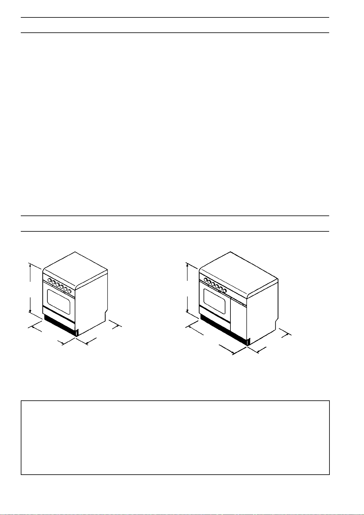
DIMENSIONS OF THE UNIT
850
600
600
850
900
550
DOOR KIT FOR ELECTRIC OVEN (CODE 35791)
Our appliances are in conformity with the EUROPEANS SAFETY REGULATIONS.
In order to further protect children from the heat coming from the oven door a special kit, which can be easily
applied to the appliance, is available.
You can buy the kit in our CUSTOMER SERVICE CENTRES; it can be requested stating the number of
PRODUCT NO. shown on the working platelet.
Instructions for the installationn are enclosed in the packaging.
29
Page 4
INSTRUCTIONS FOR THE USER
INSTALLATION
It is important that all operations are carried out by
qualified personnel, in the normal manner.
The specific instructions are describred in the chapter
on installation.
Before using the unit, take off the special protective
layer which protects the stainless steel and anodyne
tin parts.
USE
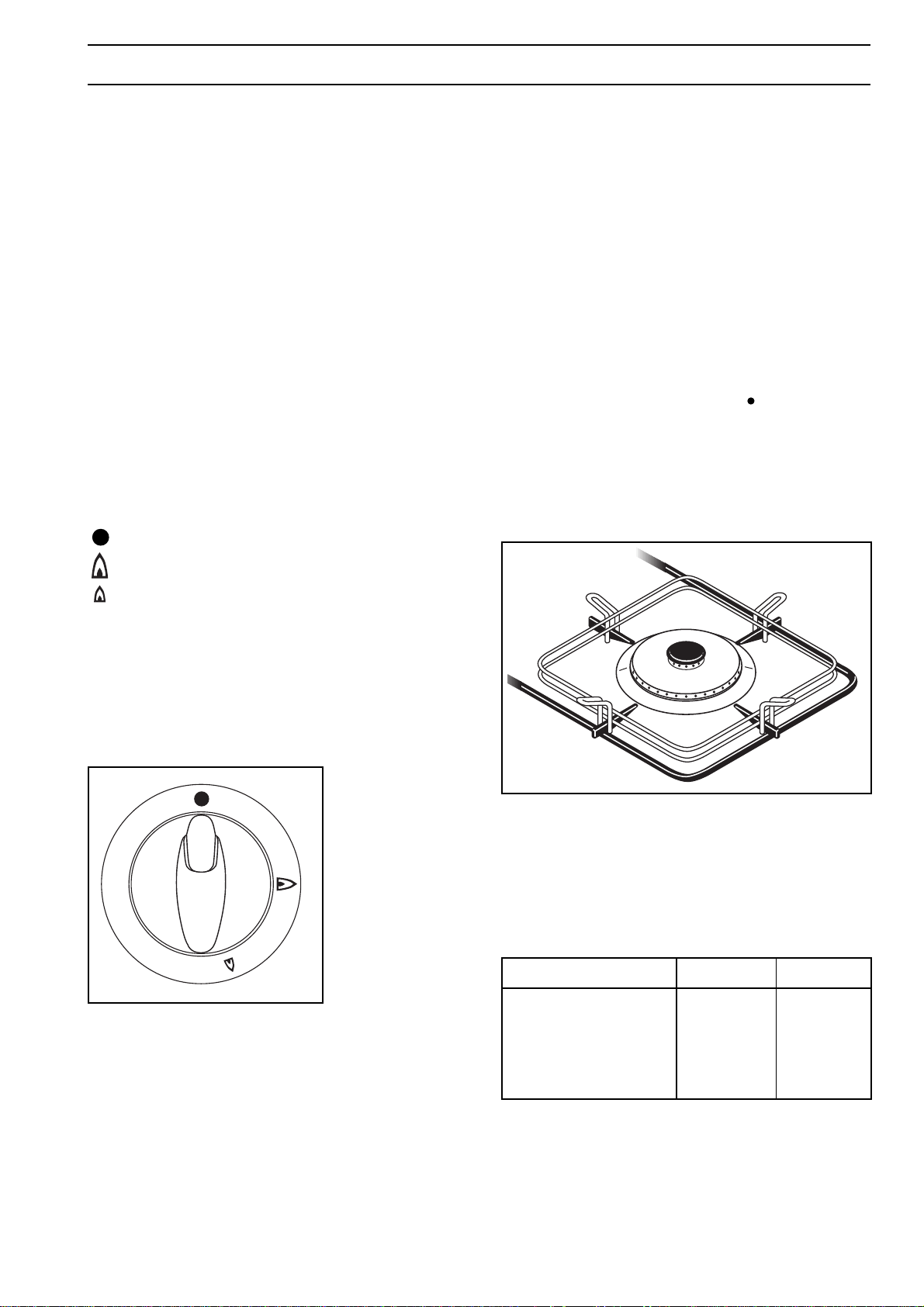
Control knobs on the cooker
The knobs for using the gas cooker are found on the
control panel.
The regulation knobs hould be turned in anti-clockwise
direction until the small flame symbol, and vice-versa
for the larger symbol.
No gas supply
Maximum gas supply
IGNITION OF HOB BURNERS
To ignite a burner, before positioning the saucepan,
use the appropriate switch marked by a small spark,
push the corresponding knob in completely and turn in
an anticlockwise direction to the maximum position;
upon ignition regulate the flame as required.
In models provided with a safety device, the control
knob must be pressed in for approximately 5 seconds
until the safety valve automatically keeps the flame lit.
If after a few attempts the burner does not ignite, check
that the baffle and its cap are correctly positioned.
To interrupt the supply of gas, turn the knob in a
clockwise direction to the position " ".
During cooking, when using fats or oils, take
particular care as they can, when over-heated, selfignite.
When using the big-rapid burner, place the special
grid on the pan support, as shown in fig.2.
Minimum gas supply
Some models are equipped with a safety-valve. In case
of extinction of the flame, this device will operate,
stopping gas supply (ex.: overflowing, draughts).
Fig. 1
Fig. 2
Table 1
Table of minimum and maximum diameters of
recipients to be placed on burners.
Burner min diam max diam
Big-Rapid (large) ø 220 mm ø 260 mm
S/Rapid (medium) ø 120 mm ø 220 mm
Auxiliary (small) ø 80 mm ø 160 mm
Fish kettle burner 120 x 270 210 x 380
30
Page 5
POTTERY
POTTERY
Remember that a wide-bottomed pan allows a faster
cooking than a narrow one.
Always use pots which properly fit what you have to
cook.
Particularly make sure that the pans are not too small
for liquids, since these could easily overflow.
Moreover, the pans should not be too large for a faster
cooking. In fact, grease and juices may spread on the
bottom and burn easily.
It is better to use non-openable moulds for baking
cakes. In fact, an openable mould lets juices and sugar
leak through, falling on the bottom of the oven and
consequently burning on the bottom of the baking tray,
making cleaning difficult.
Avoid putting plastic-handled pans in the oven as they
are not heat-proof.
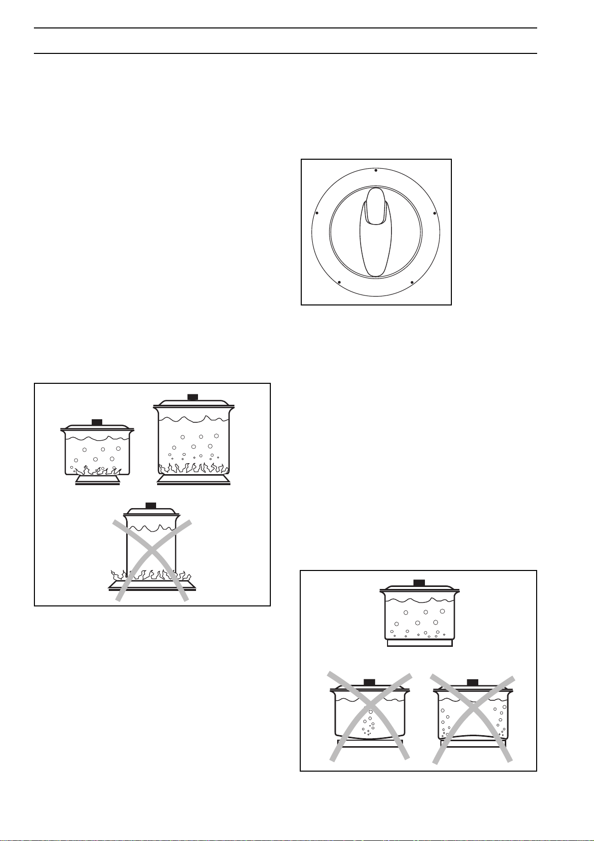
You should use oans with the right diameter to fit the
burner, in order to make the most out of it, thus
reducing gas consumption as in Fig. 3.
It is also advisable to cover any boiling casserole and,
as soon as the liquid starts boiling, lower the flame
enough to keep the boiling point.
HOTPLATES
The hotplates control knob can be adjusted on four
different positions, according to your cooking needs,
from maximun heat (position 4) to minimum heat
(position 1), as shown in Fig. 4.
0
4
3
Saucepans suitable for use on solid plate hobs should
have several characteristics:
• they should be fairly heavy duty;
• they should fit the heat area exactly, or be slightly
larger for efficient use, NEVER smaller;
1
2
Fig. 4
Fig. 3
• they should have a flat base to ensure good contact
with the plate (see Fig. 5).
This is particularly important when using pans for high
temperature frying or pressure cooking.
Ensure pans are large enough to avoid liquids being
spilt onto the plates.
Never leave the plates on without a pan on them or with
an empty pan on them.
In models supplied with a cover, if it is made of
glass, it should not be closed when the burners are
still hot, as it could splinter.
Fig. 5
31
Page 6
GAS OVEN
410
610
02
0
42
0
max
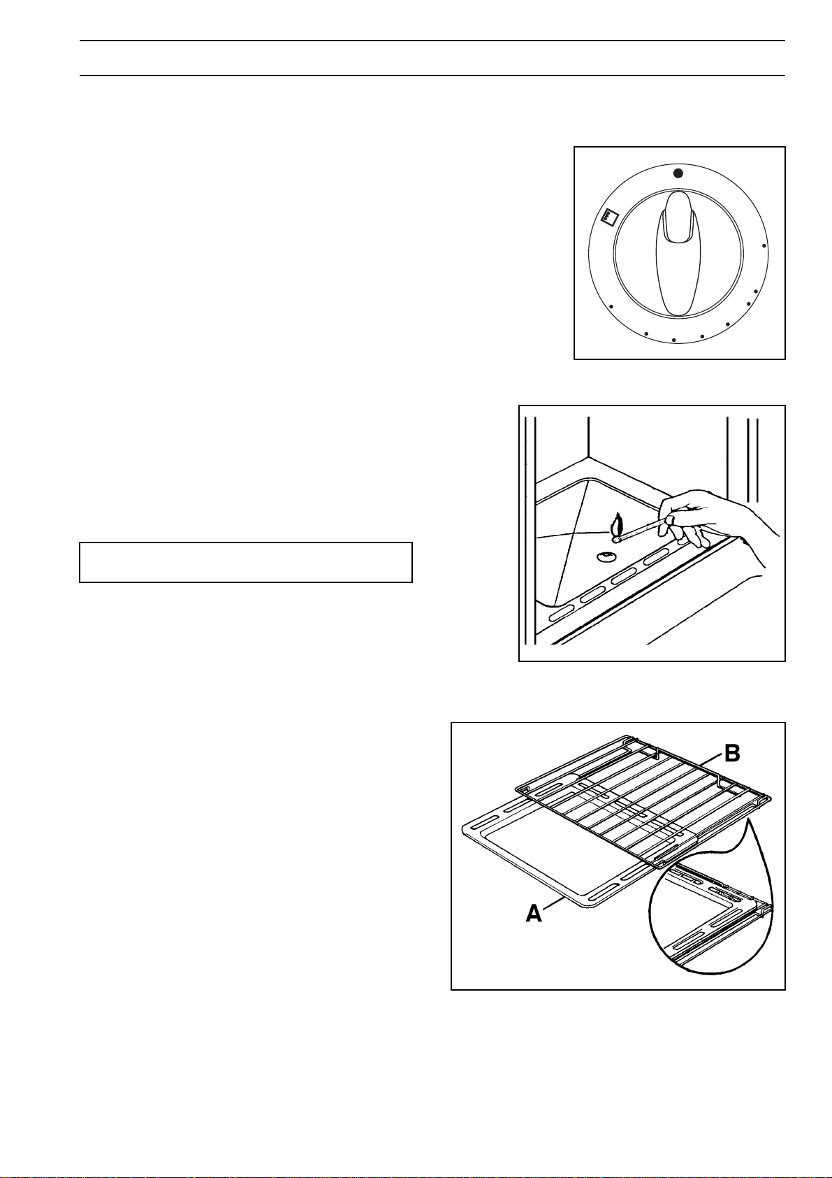
IGNITION
Open the oven door and push and turn the oven knob
(Fig. 6) in an anti-clockwise direction to the maximum
temperature position; at the same time push the
relevant button marked with a small spark. Upon
ignition keep the knob pushed in for about 10-15
seconds.
For manual ignition:
• open the oven door and hold a flame near the hole
in the bottom as shown in fig. 7;
• press the oven knob and turn anti-clockwise until
the maximum temperature position is reached;
• press in the oven knob for approximately 10-15
seconds until the safety valve automatically keeps
the oven burner lit.
If the burner does not light first time, keep the oven
door open and wait 1 minute at least before repeating
the operation. Once the oven has been lit, adjust the
flame as required.
Fig. 6
— If the flame should accidentally go out, turn the oven
knob at the "off" position (symbol "●") and wait 1
minute at least before retrying to light the burner.
Ignition of the oven burner must be carried out
with the oven door open.
When cooking with the oven or grill, the cover must
be kept open to avoid over-heating.
To adjust automatically the flame in cookers equipped
with thermostat (Fig. 6), turn the knob to the position
corresponding to the temperature desired, after a few
minutes of work.
The oven is equipped with an enamelled dripping-pan
which function is to collect the juices dripping from the
meat on the grill or on the spit, and a grid for the
cooking of foods on the grill or in a pan.
In models provided with oven grids with a position
catch (fig. 8) and when cooking on the grill or on the
spit, you are advised to fit the dripping-pan (A-fig. 8) in
the guides beneath the grill (B-fig. 8) to avoid dirtying
the oven.
if you need to place the dripping-pan over the oven grid
during cooking, position it as shown in the particular of
Fig. 8.
Fig. 7
FO 1079
32
FO 0190
Fig. 8
Page 7
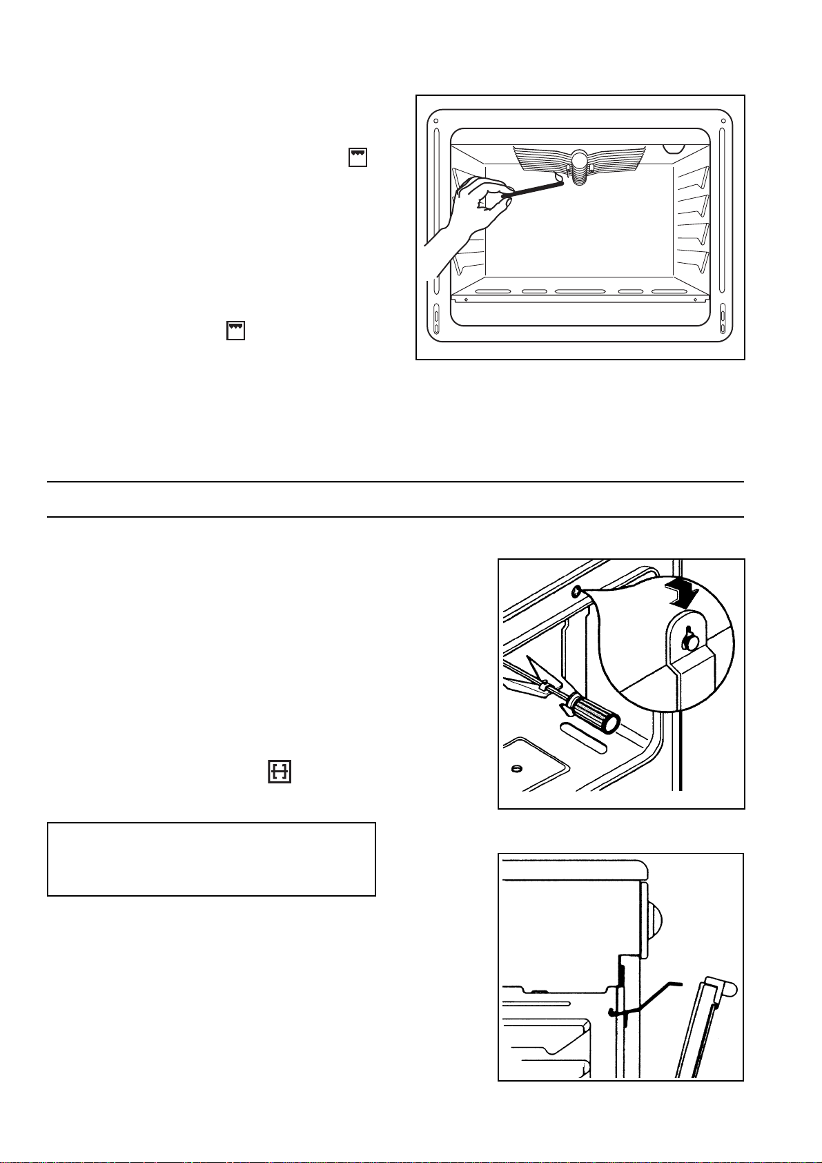
GRILL BURNER IGNITION
• Open the oven door;
• turn the oven knob (Fig.6) on the Grill symbol ;
• at the same, time push the button marked with a
little spark.
Upon ignition, keep the knob pushed in for about 5
seconds.
For manual ignition:
• open the oven door and hold a flame near the gas
grill burner holes, as shown in fig. 9;
• press the oven knob and turn it clockwise until it
points on the Grill symbol ;
• keep the oven knob pushed in for about 5 seconds
until the safety valve automatically keeps the oven
burner lit.
If the burner does not light first time, repeat the
operation keeping the knob pressed in slightly longer.
Once the oven has been lit, adjust the flame as
required.
FO 0829
Fig. 9
TURNSPIT
Some models may be equipped with a rotisserie. For
correct use, proceed as follows:
• fit the spit-holder hook on the support (fig. 10);
• slide the spit into the food to be cooked and secure
well;
• rest the front part of the spit on the hook, ensuring
that the point of the spit is well inserted into the
rotisserie motor housing (fig. 10);
• remove the handle;
• turn the oven knob to the grill position or, when
required for some models, turn on the motor by
means of the appropriate switch .
When cooking with the rotisserie you are advised
to leave the oven door half open and to fit the knob
protection shield as shown in fig.11.
Fig. 10
FO 0706
Fig. 11
FO 0375
33
Page 8
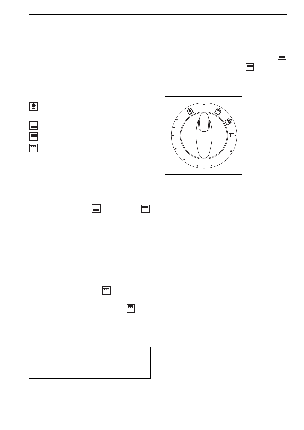
ELECTRIC OVEN
Control knob (fig. 12)
It makes it possible to choose the most appropriate
temperature and to select the elements radiating heat
one by one.
Explanation of symbols:
0 Oven in off position
Oven light
50-max
To select the temperature, turn the knob clockwise
until the pointer is on the position indicating the desired
temperature, included hetween 50°C and max.
The temperature will be kept constant by the
thermostat.
If you want more heat coming from the bottom or more
heat coming from the top turn the knob so as to place
Temperature
Bottom heat
Top heat
Grill
Under these conditions the temperature will never
exceed about 200°C in the bottom heat position
and 180°C in the top heat position and it will not
he regulated by the thermostat.
0
05
0
10
510
0
0
max
2
Fig. 12
the pointer on the symbol (bottom heat) or
(top heat).
ELECTRIC STATIC GRILL
In the models with electric oven turn the knob so as to
place the pointer on the symbol .
In the models with gas oven press and turn the knob
clockwise until the stop position is reached , at the
same time the grill light will come on.
Place the dripping pan under the wire shelf so as to
prevent fat from dripping on the bottom of the oven.
In the models with electric oven it is necessary,
while the grill is in function, to leave the door halfopen and to put the protective screen to the knob
(fig. 11).
34
Page 9

ELECTRIC OVEN (5 FUNCTIONS)
Command selection switch (Fig. 13) and
thermostat (Fig. 14).
It allows to choice the most suitable heat for different
types of cooking by inserting suitable heating elements
and regulating the temperature to the degree required.
The oven light stays lit in all selector positions.
Symbol meanings:
upper and lower heating elements
grill element
lower heating element
upper and lower heating element + fan
defreezing
Traditional cooking
Turn the selector switch until the mark coincides with
the position and the thermostat until it coincides
with the temperature required.
Grilling
Turn the selection switch to , then turn the
thermostat knob until it coincides with the tempera-
ture required.
Cooking with the lower element
Turn the selector switch to position , then turn the
thermostat knob until it coincides with the tempera-
ture required.
When using the grill in models having 5
function oven, the oven door must be kept
half-open and the knobs-protection shield
(fig. 11) must be in position.
Cooking by convection
Turn the selector switch to position , then turn the
thermostat knob until it coincides with the tempera-
ture required.
Defreezing
Turn the selector switch to position .
In this way the motorized fan is inserted. By moving
the cold air inside the oven this permits frozen foods
to be quickly defreezed.
With the selector knob (Fig. 11) in position turn the
oven thermostat knob (Fig. 12) to position « »
Oven light switch
It allows the oven internal light to be switched on.
Operational pilot light (Red light)
When lit, it shows the insertion of one or more
heating elements.
Oven thermostat pilot light (Yellow light)
It turns off when the oven reaches the selected temperature and re-lights when the heating elements
operate to stabilize the temperature.
In order to avoid over-heating when cooking
with the oven or grill, always keep the
appliance cover open.
The oven is supplied with an enamelled dripping pan,
meant to collect juices dripping from meat placed on
the grid, and an proper grid for grid-cooking.
When using the oven grill, it is advisable to insert the
dripping pan (A - Fig. 15) in the relevant guide under
the special grid (B - Fig. 15), supplied with some of our
models. This can avoid the axcessive dirtying of the
oven.
If you need to place the dripping pan over the grid when
cooking, position it as shown in the particular of Fig. 15.
Fig. 13
Fig. 14
Fig. 15
0
05
010
2
0
510
0
FO 0190
35
Page 10

A
B
C
Mechanical minute-minder
The minute-counter may be set for a maximum time of
one hour. The regulation knob (fig. 16) must be turned
clock-wise until the 60-minute position is reached and
then anti-clockwise to the required time.
Once the pre-set time has elapsed, a signal will be
heard which automatically cuts out. The oven,
however, will remain on.
PROGRAMMING OF COOKING
0
5
01
05
51
02
04
03
Fig. 16
End of cooking digital programmer (Fig. 17)
In some models it has the function of switching off the
oven at the end of pre-selected cooking time.
The programmer has an electric clock which shows the
time of day and a timer with an acoustic signal.
Fig. 17 illustrates the programmer’s commands;
switches A and B carry out the necessary regulations
foreseen, as follows:
Switch A
Turned in a clockwise direction allows to adjust the time
shown on the digital clock (at the time of installation,
after electricity cuts, to advance or turn back, etc.).
Switch B
Turned in a clockwise direction sets:
- the length of cooking time (max. 210 minutes);
- interruption of the acoustic signal (position );
- manual operation (position ).
The above signals appear on face C.
Programmed operation of the oven
- Prearrange the food to be cooked;
-
turn switch B in a clockwise direction and preset the
minutes presumed for the end of cooking on switch C;
- turn the oven switch to the temperature required.
At the end of the pre-set time an acoustic signal will be
heard; to switch it off, turn knob B to symbol visible
on face C, corresponding to the mark on the face itself.
Manual operation
The oven can be used normally, i.e. without any
programme. In such case, switch B of the programmer
should be turned in a clockwise direction until symbol
coincides with the mark on face C.
36
FO 0158
Fig. 17
Page 11

SUGGESTIONS FOR GAS BURNERS
Start your cooking with a big flame by turning the knob
to the symbol . Then adjust the flame as necessary.
The outside of the flame is much hotter than its inside
(nucleus). Accordingly , the top of the flame should lick
the bottom of the pan. Excessive flames mean a waste
of gas.
In contrast with electric grids, gas burners do not
require flat-bottomed pans: the flames lick the bottom
and spread the heat all over the surface.
No special pans are required for gas burners.
However, thinwalled pans transmit the heat to the food
more quickly than thick-walled ones.
Since heat doesn't spread evenly on the pan's bottom,
the food may only be partially heated. Consequently it
is advisable to stir the food many times.
A thick pan bottom prevents partial overheating as it
allows sufficient thermic compensation.
Avoid very small pans. Wide and shallow pans are
more suitable than narrow and deep ones as they allow
a faster heating. Cooking is not quickened by placing
narrow pans on wide burners. The result is just a waste
of gas. For a proper usage, place small pans on small
burners and large pans on large burners.
Remember to cover pans to reduce gas consumption.
SUGGESTIONS FOR OPERATING OF OVEN
Traditional cooking
Heat derives from the top and the bottom, it is therefore
preferable to use the central guides. If cooking requires
more heat from the bottom or the top, use the upper or
lower guides.
Convection cooking
Heat is transmitted to food through pre-heated air and
is forcibly circulated inside the oven by a fan positioned
on the back of the oven itself. In this way heat quickly
and uniformly reaches all parts of the oven thus
cooking various foods placed on more than one shelf.
With this type of cooking the elimination of humidity
from the air and a drier environment prevent the
transmission and mixture of smells and tastes.
The possibility of cooking on more than one shelf
allows many various dishes to be prepared at the same
time, and up to three trays of biscuits or mini-pizzas to
be consumed immediately or to be frozen. The oven
can, however, be used for cooking on only one shelf.
In such case use the lower guides in order to observe
cooking better.
Furthermore, this oven is especially convenient for
quick defreezing, sterilizing preserves, homemade fruit
in syrup and finally to dry mushrooms or fruit.
Cooking with the multi-function oven
With this type of oven it is possible to carry out cooking
traditionally, by convection, and by grill; it therefore
allows cooking to be optimized.
ADVICE FOR USE OF THE TRADITIONAL
OVEN (GAS OR ELECTRIC)
For the cooking of cakes
Pre-heat the oven , unless indicated differently, for at
least 10 minutes before use. Do not open the oven
door when cooking dishes which must raise (e.g.
raised pastries and soufflés); the jet of cold air would
block the raising process. To check if cakes are
cooked, insert a toothpick into the mixture; if it comes
out clean the cake is ready. Wait until at least 3/4 of
the cooking time has passed before doing this check.
As a general rule remember that:
a dish which is well-cooked on the outside but not
sufficiently cooked inside would have required a lower
temperature and longer cooking time. On the contrary,
a “dry” texture would have required a shorter time and
higher cooking temperature.
For the cooking of meat
Meat to be cooked in the oven should weigh at least 1
kilo to avoid its becoming too dry. If you want roasts
with a good colour, use very little oil. If the piece is
lean, use oil or butter or a little of both. Butter or oil are
on the other hand unnecessary if the piece has a strip
of fat. If the piece has a strip of fat on one side only,
put it in the oven with this side upwards; when melting
the fat will grease the lower side sufficiently.
Red meat should be removed from the fridge one hour
before cooking otherwise the sudden change of temperature could cause it to become tough. A roast,
especially if of red meat, must not be salted at the
beginning of cooking as salt causes juices and blood
to seep out of the òmeat, thus preventing the formation
of a well-browned crust.
It is advisable to salt the outside of the meat after just
over half the cooking time.
Place the roast in the oven in a dish having a low rim;
a deep dish shields heat.
Meat can be placed on an ovenproof dish or directly
on the grill, under which the dripping pan will be
inserted to collect juice. Ingredients for gravy should
only be put in the dish immediately if cooking time is
brief, otherwise they should be added during the last
half hour.
37
Page 12

Begin cooking rare meat at a high temperature,
reducing the temperature to finish cooking the inside.
The cooking temperature for white meat can be moderate throughout.
The degree of cooking can be checked by pressing the
meat with a fork; if it does not give the meat is cooked.
At the end of cooking it is advisable to wait at least 15
minutes before cutting the meat in order that the juices
are not lost.
Before serving plates can be kept warm in the oven at
minimum temperature.
should be positioned in the guides nearest or furthest
from the grill element according to the thickness of the
meat, in order to avoid burning the surface and
cooking the inside insufficiently.
The formation of smoke caused by drops of juice and
fat can be avoided by pouring l or 2 glasses of water
into the dripping pan.
The grill can also be used to brown, toast bread and
grill certain types of fruit, such as bananas, halved
grapefruit, slices of pineapple, apples, etc. Fruit
should not be placed too near the source of heat.
For the cooking of fish:
Cook small fish from start to finish at a high temperature. Cook medium-sized fish initially at a high temperature and then gradually lower the temperature.
Cook large fish at a moderate temperature from start
to finish.
Check that baked fish is cooked by gently lifting one
side of the gut; the meat must be white and opaque
throughout, except in the case of salmon, trout or
similar.
Grilling
The following types of meat are suitable for grilling.
Mostly meat or offal cut in slices or pieces of various
sizes, but not usually very thick, poultry cut in half and
flattened, fish, some vegetables (e.g. courgettes,
aubergines, tomatoes, etc.), skewers of meat or fish
and seafood.
Meat and fish to be grilled should be lightly brushed
with oil and always placed on the grill; meat should be
salted upon completion of cooking; whereas fish
should be salted on the inside before cooking. The grill
Cooking times
Cooking times can vary according to the type of food,
its consistency and its volume. It is advisable to watch
when cooking for the first time and check results since
when preparing the same dishes, in the same
conditions, similar results are obtained.
The “TABLE OF COOKING TIMES” relating to
cooking in the oven and by grill is provided as a guide.
Experience will show possible variations to the values
set out in the table.
Nevertheless carefully follow the indications given
in the receipe you intend to follow.
Attention: do not place any utensils such as dripping
pan, cake tins, casseroles, pyrex dishes, aluminium
foil or other on the base of the oven when the oven is
in use. A stagnation of heat would result which would
compromise the results of cooking and could damage
the oven enamel.
38
Page 13

TIPS ON COOKING WITH MULTIFUNCTION ELECTRIC OVEN
Traditional cooking
Heat is conveyed both from the top and bottom of the
oven; thus, it is advisable to put the pot in the central
shelves position. When a higher heat is required either
from the top or bottom, put the pot in an upper or lower
position.
Suggestions for traditional baking
How to bake cakes
Cooking of cakes require a moderate temperature
(usually ranging between 150/200°C) and a 10-minute
pre-heating of the oven. The door should not be
opened during the first 3/4 of the whole baking time.
Beaten up dough should be firm enough to avoid a
longer baking time. When cakes and canapees are
arranged simultaneously on 3 shelves, a runner
should be skipped between the 2 lower shelves (see
Fig. 18).
How to cook meat and fish
Meat should weigh at least 1 kg to avoid excessive
drying. Very soft red meats, to be left rare or only welldone on the outside while keeping their juices, require
a short but high temperature (200-250°C).
White meat, fowl and fish require a low temperature
(150-170°C).
Ingredients for the gravy should be added to the baking
pan only in the last half hour, unless cooking time is
very short.
The baking point of meat can be checked by pressing
a spoon against the meat. If it feels firm it is properly
cooked, Roastbeef and sirloin require a short cooking
time, as thier insides must keep their redness.
Meat can either be placed an a suitable baking pan or
directly on the grid under which the plate is to be
inserted to collect the juices. When baking time is over
it is advisable to wait at least 15 minutes before slicing
the meat to avoid any spilling of juices.
Dishes can be kept warm in the oven at the lowest temperature, before being served.
Grilling
Heat comes from the top of the oven. It is suitable for
thin meat, toast.
Tips on grill cooking
Almost all kind of meat can be cooked with grill, except
for some game lean meat and meat loaves.
Meat and fish to be grilled should be lightly brushed
with oil and always placed on the grill; meat should be
salted upon completion of cooking; whereas fish
should be salted on the inside before cooking. The grill
should be positioned in the guides nearest or furthest
from the grill element according to the thickness of the
meat, in order to avoid burning the surface and cooking
the inside insufficiently.
The formation of smoke caused by drops of juice and
fat can be avoided by pouring l or 2 glasses of water
into the dripping pan.
FO 0061
Fig. 18
39
Page 14

COOKING T ABLES
Kinds of food
Temperature
°C
Inserting slide*
Ordinary
electric oven
Gas oven
Cooking
time in
minutes
Beaten mixture cakes in moulds
Black and white flour cake 175 2 2 60-70
Royal flat bread-cake 175 2 3 60-70
Margherita cake 175 2 3 35-40
Pastry
Bottom of cake to be garnished 200 2 3 15-20
Butter-milk curd cake 200 1 2 35-40
Jam cake 200 1 2 35-40
Leavening dough cakes in moulds
Brioche 200 2 2 35-40
Small cakes
Pastry 170 2 3 10-15
Cream puff 200 2 3 30-40
Meringue 140 2 3 120
Lasagne 225 2 2 40-50
Meat (cooking time for every cm of thickness)
Long cooking roast meat 175 2 2 12-15
Short cooking roast meat 200 2 2 10-12
Meat-loaf 200 2 2 30-40
Poultry
Duck 1 1/2 - 2 kg 200 2 2 120-180
Goose 3 kg 200 2 2 150-210
Roast chicken 200 2 2 60-90
Turkey 5 kg 175 2 2 about 240
Game
Hare 200 2 2 60-90
Roe-deer rib 200 2 2 90-150
Deer haunch 175 2 2 90-180
Vegetables
Boiled vegetable flan 200 2 2 40-45
Fish
Grey mullets 200 2 2 40-50
Pizza 240 1 2 20-25
Grill
Chops 3 3 15-20
Sausages 3 3 20-25
Grilled chicken 2 2 60-70
Roast veal on the spit 0,6 kg 70-80
Chicken on the spit 60-90
* The number of the slide refers to the lowest one (excepted the position on the bottom of the oven, since the dripping pan can't
be inserted).
GRILL COOKING TIMES
TRADITIONAL GRILL COOKING
Tipes Quantity kg N. of the slide from the bottom Temperature °C Time in
(grill position) Minutes
Chicken 1-1,5 3 Max 30 a side
Toast 0,5 4 Max 5 a side
Sausages 0,5 4 Max 10 a side
Chops 0,5 4 Max 8 a side
Fish 0,5 4 Max 8 a side
40
Page 15

COOKING T ABLES
ELECTRIC MULTI-FUNCTION OVEN
Temperature °C N. Guiderom bottom
Type of cooking Quantity kg Conv. Trad. Conv. Trad. Time
Cakes
With beaten mixture, in mould 1 1-3 2 175 200 60
With beaten mixture, in baking tin 1 1-3 2 175 200 50
Shortpastry, cake tin 0,5 1-3 3 175 200 30
Shortpastry with wet filling 1,5 1-3 2 175 200 70
Shortpastry with dry filling 1 1-3 2 175 200 45
With naturally raised mixture 1 1-3 1 175 200 50
Little cakes 0,5 1-3 3 160 175 30
Meat
Veal 1 2 2 180 200 60
Beef 1 2 2 180 200 70
English roastbeef 1 2 2 220 220 50
Pork 1 2 2 180 200 70
Chicken 1 ÷ 1,5 2 2 200 200 70
in
Minutes
Casseroles
Beef casserole 1 1 2 175 200 120
Veal casserole 1 1 2 175 200 110
Fish
Filets of cod, hake, sole 1 1-3 2 180 180 30
Mackeral, turbot, salmon 1 1-3 2 180 180 45
Oysters 1-3 2 180 180 20
Flans
Macaroni pie 2 1-3 2 185 200 60
Vegetable flan 2 1-3 2 185 200 50
Sweet or savoury souffles 0,75 1-3 2 180 200 50
Pizzas and calzone 0,5 1-3 2 200 220 30
Defreezing
Prepared dishes 1 2 200 45
Meat 0,5 2 50
Meat 0,75 2 70
Meat 1 2 110
1. Cooking times are intended after pre-heating ythe oven for approximately 15 minutes.
2. When cooking on more than one shelf, the guide indicated is the one which is prferable.
3. Times refer to cooking on only one shelf, for more shelves increase the time by 5-10 minutes.
4. For roasted beef, veal, pork or turkey with bone or rolled increase times by 20 minutes.
41
Page 16

MAINTENANCE
Before each operation, disconnect the unit.
Cleaning the cooker
Drops of sauce, fruit juice etc., should be removed as
soon as possible with a soft cloth soaked in warm
detergent water. Do not use steel wool or knives to take
off layers of crust. Remove stubborn marks with a well
wetted soap impregnated pad, but care must be taken
not to scratch the enamel. Wash the enamelled grids
with water and detergent; these can also be washed a
dishwasher.
Take off the burner covers and the grids and wash
them carefully with warm water and detergent. Dry
them well before putting them back in position.
Moreover, make sure that these are properly re-placed.
The burner can be rubbed with steel wool or a slightly
abrasive cloth.
Clean the oven door and crystal cover, in models
equipped with these items, only with warm water, and
avoid the use of rough cloths or abrasive substances;
in cookers with an automatic ignition the sparkling bulb
should be cleaned periodically and accurately to avoid
difficulties in lighting; furthermore check that the burner
holes are not obstructed.
inside the holder itself; otherwise there is the chance
to install inside the holder, instead of the cylinder, (on
request) a set of grills and containers, converting the
cylinder holder into a comfortable closet.
Oven lamp replacement (Fig. 19)
Disconnect the appliance. Unscrew the lamp and
substitute it with another fitting for a higher tempera-
ture (300°C) with the folowing characteristics:
Tension: 230 V (50Hz)
Power: 15W
Convection: E14
Cleaning the oven
Clean carefully the oven cavity after use when it is still
warm. In fact, at this moment it is easy to take off
deposits of fat or other substances such as fruit juice,
sugar particles or fat. You can use warm detergent
water or one of the appropriate spray oven cleaners.
Do not direct the spray at the mat steel parts as this
could damage them and always follow the
manufacturer's instructions. Clean the oven accessories (grate, grid-plate etc.) with warm water and
detergent.
Remove possible incrustations with a slightly abrasive
powder.
Never line any part of the oven with aluminium foil.
It would result in an accumulation of heat which
might damage the cooking results and also
damage the enamel.
Controls - Sundries
Periodically check the condition of the flexible pipe of
gas connection and make it replaced by skilled
technicians as soon as it shows abnormalities. Annual
replacement is recommended.
Have the cocks periodically lubricated by skilled
technicians. In case of unusual working have the range
checked by skilled technicians.
In ranges with cylinder holder, do not use this space to
leave a non-connected or an empty cylinder.
FO 0424
Cleaning the oven door
For a more complete cleaning of the oven door, it is
advisable to disassemble it in the following way (Fig.
20): open the door fully, turn the two caps situated on
the arm of the hinge to 180°, partially close the door to
an angle of 30°, lift the door and extract from the front.
Re-mount the door by reversing the operation
described above.
Fig. 19
Cylinder holder
The units equipped with cylinder holder must be
installed in such a way to ensure a sufficient ventilation
42
FO 0967
Fig. 20
Page 17

Lid cleaning
All the cooker lids can be disassembled, to allow a
better cleaning.
Enamelled lids can be dissasembled as shown in fig. 21.
As regards crystal lids, follow instructions included in
the chapter named "Balancing the lid".
After a proper cleaning, carefully reposition the lid into
its hinges.
Fig. 21
INSTRUCTIONS FOR THE INSTALLER
The following instructions are meant for a qualified
installer, in order that the operations of installation,
regulation, and service are executed according to the
existing regulations.
Whenever changes are mode involving the
disconnection of the machine it is necessary to
proceed with maximum caution.
THE MANUFACTURING COMPANY DECLINES ANY
RESPONSABILITY FOR POSSIBLE DAMAGES
RESULTING FROM AN INSTALLATION WHICH
DOESN'T COMPLY WITH THE RULES IN FORCE
INSTALLATION ENVIRONMENT
Warning - This unit can be installed and can work only
in constantly ventilated rooms, according to rules in
force.
In order to make the gas unit work properly, it is
necessary that air sufficient to gas combustion can
naturally flow in the room. (The installer must follow the
rules in force).
The air flow into the room must come directly through
openings of external walls - See fig. 22-23.
These openings must have a free passage of at least
200 cm2 (one or more openings can be made).
These openings (or opening) should be realized in
such a way not to be occluded both from inside and
outside and preferably positioned near the floor,
opposite the combustion products discharge. In case
these systems can't be realized in the room where the
unit is installed, the necessary air can come from a
room nearby, provided that this room is not a bedroom
or a dangerous environment and it is ventilated as
requested.
FO 0418
AIR INLET
ENTRATA ARIA
SECTION
SEZIONE MIN.
MIN. 200 cm
200 cm
FO 0159
FO 0160
2
2
Fig. 22
AIR INLET
ENTRATA ARIA
SECTION
SEZIONE MIN.
200 cm
MIN. 200 cm
2
2
Fig. 23
43
Page 18

COMBUSTION PRODUCTS DISCHARGE
ENTRATA ARIA
SEZIONE MIN.
200 cm
2
CAPPA
Gas cooking units must discharge combustion products
through hoods directly connected to flues or outside
(Fig. 24).
In case the hood can't be installed, it is recommended
the use of an electric fan applied to the external wall or
to the window of the room, provided the kitchen has the
proper openings for air inlet
This electric fan must be powerful enough to ensure an
air replacement of 3 to 5 times the room's volume per
hour.
(Fig. 25).
HOOD
AIR INLET
SECTION
MIN. 200 cm
2
POSITIONING
This appliance belongs to the class "X".
It has been designed to be placed close to furniture
units not exceeding the height of the working level (EN
60 335-2-6).
LEVELLING
The appliance is provided with adjustable small feet
placed in the back and front corners od the base.
By adjusting the small feet (fig. 26) it is possible to
change the height of the appliance so as to ensure a
better levelling with other surfaces and a uniform
distribution of the liquids contained in pans or pots.
BALANCING THE LID
The models provided with crystal lids are equipped with
specially balanced springs, inserted in the hinges at the
back of the appliance, to allow the lid to be closed
smoothly and easily.
You can use a screwdriver to adjust the closure of the
lid. The necessary force for opening/closing the lid can
be increased by turning the adjusting screw 2 or 3
times as shown in Fig. 27.
Fig. 24
Fig. 25
FO 0161
FO 0439
ELECTRIC FAN
ELETTROVENTILATORE
AIR INLET
ENTRATA ARIA
SECTION
SEZIONE MIN.
200 cm
MIN. 200 cm
PIU' LA SEZIONE
plus an added
AGGIUNTIVA
section
CORRISPONDENTE
ALLA PORTATA
corresponding
DELL'ELETTRO-
to electric
VENTILATORE
fan power
2
2
GAS CONNECTION
Gas connection must be carried out according to the
rules in force.
The manufacturing company release the unit, once
tested, adjusted for the kind of gas stated on the rating
plate located on the back of the range, next to
connection pipe. Be sure that you are going to connect
the unit to the same kind of gas written on the plate.
Otherwise, follow all the instructions of the paragraph
"REGULATION TO DIFFERENT KINDS OF GAS".
For best efficiency and lowest consumption, be sure
that manifold gas pressure respects the values in the
table of "Burners characteristics".
If gas pressure is different (or variable) from the proper
one, a suitable pressure regulator should be installed
on feeding pipe.
The use of pressure regulators for liquid gas (LPG) is
allowed provided they are modelled in conformity with
the rules in force
44
Fig. 26
Fig. 27
FO 0063
FO 0064
Page 19

CONNECTION USING A RIGID PIPE OR A
FLEXIBLE METAL PIPE
To ensure higher safety, it is recommended to carry out
the connection to the gas system using rigid pipes (ex.
copper) or using flexible stainless steel pipes, to avoid
any stress to the unit.
Gas feeding pipe fitting is Gc 1/2.
For this type of installation, connection to the gas
supply should be carried out using only and exclusively
flexible metallic tubes in conformity with rules in force.
IMPORTANT
Once installation is complete, check the perfect seal of
every pipe fitting, using a soapy solution, never a flame.
YES
FLEXIBLE
RUBBER
GAS PIPELINE
CONNECTION USING FLEXIBLE,
NON METAL PIPES
When the connection can be easily inspected in its full
extent, there is the chance to use a flexible pipe
according to the rules in force.
The flexible pipe must be tightly fixed using clamps
according to the rules in force.
The flexible pipe should be made ready for use in such
a way that:
- nowhere it can reach overtemperature, other than
room temperature, higher than 30°C; if the flexible
pipe, to reach the cock, must run behind the range,
it must be installed as shown in Fig. 28;
- it is no longer than 1500 mm;
- it shows no throttles;
- it is not subject to traction or torsion;
- it doesn't get in touch with cutting edges or corners;
- it can be easily inspected in order to check its
condition.
The control of preservation of the flexible pipe consists
in checking that:
- it doesn't show cracks, cuts, marks of burnings both
on the end parts and on its full extent;
- the material is not hardened, but shows its normal
elasticity;
- the fastening clamps are not rusted;
- expiry term is not due (5 years).
ELECTRIC
WIRE
NO
FLEXIBLE
RUBBER
GAS PIPELINE
ELECTRIC
WIRE
FO 0163
Fig. 28
If one or more abnormalities are seen, do not repair the
pipe, but replace it.
To connect the range to LPG cylinder, use a flexible
pipe, introducing it into the cylinder holder through the
lower opening in the back and set it in position
fastening it with the two laces, as shown in Fig. 29
Attention: it should never touch the left side of the
holder.
Use the proper holder bottom (A - Fig. 29) to avoid the
cylinder touch the floor.
Fig. 29
FO 0698
45
Page 20

ADAPTATION TO DIFFERENT
KINDS OF GAS
To adapt the appliance to a different kind of gas from
the one the appliance has been set for, follow the
instructions below in their order.
Replacement of rubber pipe holder (Fig. 30)
LPG preset range:
to set the range ready for natural gas, use rubber pipe
holder «A».
Natural gas preset range:
To set the range ready for LPG, use the rubber pipe
holder «B» (in the equipment). Always insert the gasket
«C» between the feeding pipe and the rubber pipe
holder. (Fig. 30)
Replacement of the big-rapid and fish-kettle
burners nozzle (for models supplied with)
a) Remove the plate or glass lid by lifting it from the
relevant brackets;
b) remove the pan supports;
c) unthread the caps, baffles and burner covers;
d) dismount the two lid supports by unscrewing the
relevant fixing screws (fig. 32);
e) lift the working plate slightly from the bottom and
remove it, pushing it towards the front of the cooker;
f) FISH-KETTLE BURNER: with a no.7 spanner,
unscrew, remove and replace the nozzle (Fig. 33 A) with the proper one (see table 2 - "Nozzles").
g) BIG-RAPID BURNER: lift the burner mixing tube
(Fig. 34 - B), unscrew the nozzle (Fig. 34- A) by
means of a no. 7 spanner, remove and replace it
with the proper one (see table 2 - "Nozzles").
For primary air regulation, check the air regulator
(fig. 34 - D) is correctly positioned, that is each air
port (Fig. 34 - E) is 3 mm. wide, both for natural gas
use and LPG use. In case this condition is not
satisfied, undo the fixing screw (Fig. 34 - C) and
turn the air regulator until the measure is correct.
Remount the parts following the operations described
in reverse.
FO 0067-B
Fig. 30
Replacement of nozzles and adjustment
Nozzle replacement:
- Remove the pan supports.
- Extract the caps and the wall baffles of the burners.
- Using a socket spanner 7 unscrew and remove (fig.
31) the nozzles replacing them with the ones required
for the kind of gas in use (see table 2).
Reassemble the parts following the same procedure
backwards.
These burners do not need any primary air regulation.
FO 0392
Fig. 31
FO 0070
A
Fig. 33
B
C
E
FO 0069
46
Fig. 32
A
D
FO 2102
Fig. 34
Page 21

Adjustment of minimum level of plate burners
To adjust the minimum level:
1) turn the knob to the position of minimum flame;
2) remove the knob (Fig. 35);
3a) in case of conversion from natural gas to LPG,
tightly screw the by-pass pin of the cocks;
3b) when converting from LPG to natural gas unscrew
about one-fourth turn by-pass pin, until a regular
small flame is reached.
Reassemble the parts following the same procedure
backards.
Check that, turning quickly the knob from the maximum
position to the minimum one, the flame does not go out.
Replacement of oven burner nozzle
To replace the oven nozzle, follow this procedure:
a) remove the bottom of the oven;
b) unscrew screw 1 (fig. 36) and take the oven burner
out;
c) with a socket spanner 7 unscrew and remove the
nozzle, situated in the bottom of the oven, and
replace it with the proper one (see Table 2);
d) reassemble the burner following the same proce-
dure backwards.
FO 0068
Fig. 35
Replacement of grill burner nozzle
To replace the grill burner nozzle, act as follows:
a) remove the screws, marked with letter "A" in Fig.
37;
b) take the grill burner out;
c) with a socket spanner n.7, unscrew and remove the
nozzle, situated in the oven top, and replace it with
the proper one (see Table 2);
d) reassemble the burner following the same proce-
dure backwards.
Minimum level adjustment of oven burner
After setting the oven on maximum temperature with
closed door for about 10 minutes, turn the knob of the
thermostat on 140, remove the knob and:
— in case of conversion from natural gas to LPG,
tightly screw the by-pass pin of thermostat (fig. 35);
— converting from LPG to natural gas, unscrew the
by-pass pin, until a regular small flame is reached.
Oven and grill burners don't need any primary air
regulation.
Fig. 36
FO 1072
A
Fig. 37
47
Page 22

ADJUSTMENT OF THERMOSTAT
BY-PASS PIN
To reach the thermostat by-pass pin, act as follows:
- take out the knobs;
- remove the front panel;
- adjust the by-pass pin with a thin screwdriver, as
shown in Fig.38;
- finally check that turning quickly the tap from
maximum position to minimum position, the flame
does not go out;
- reassemble the front panel and the knobs.
FO 1061
Fig. 38
SPECIFICATIONS OF BURNERS AND INJECTORS
TYPE BURNER INJECTORS NORMAL REDUCED NORMAL FEEDING
OF GAS POWER POWER POWER PRESSURE
NATURAL
GAS
(Methane)
LIQUID
GAS
(But./
Prop.)
1/100 mm kW kW m bar
Big-Rapid 145 4,0 1,2 0,381 -
Semi-rapid 96 2,0 0,45 0,190 - 20
Auxiliary 70 1,0 0,33 0,095 -
Fish kettle burner 119 3,0 0,85 0,286 -
Oven burner 116 3,0 1,0 0,286 -
Grill Burner 111 2,5 - 0,238 -
Big-Rapid 95 3,8 1,2 - 274
Semi-rapid 71 2,0 0,45 - 144
Auxiliary 50 1,0 0,33 - 72
Fish kettle burner 88 3,2 0,85 - 230 28-30/37
Oven burner 82 3,0 1,0 - 216
Grill burner 74 2,3 - - 166
m3/h g/h
Table 2
WARNING
If the pressure of gas used is different (or variable) from that foreseen , an appropriate pressure regulator must be installed
on the entry tube.
in case of pressure regulators for GPL are used, these must conform to regulation.
48
Page 23

INSERTION POSSIBILITY
In case of insertion of the appliance between kitchen
units, the dimensions to be respected are shown in fig.
39.
When the kitchen is installed according to class 2, sub-
class 1 (i.e. built-in) for the gas connection use only
flexible metallic tubes conforming to rules in force.
100
500
650
ELECTRICAL CONNECTION
The unit is preset to work with a voltage of single phase
230 V.
Before making the connection make sure that: the
energy power available in the user's house is sufficient
for the normal supply of this appliance (see rating
plate). The unit is correctly connected to earth through
a suitable plug and according to the installation country
Laws.
The socket or the omnipolar switch used for the
connection must be easilv reached with the installed
appliance. The appliance is supplied without electric
cord: consequently, you have to install a plug fit for the
load shown in the serial number plate. The plug has to
be connected to an adequate socket.
If you wish to directly connect to the mains, you have
to interpose an omnipolar switch with a minimum
opening between contacts of 3 mm, between the unit
and the mains, complying with the existing regulations.
The brown live wire (originating from the clamp of the
cooker junction box) must always be connected to the
phase of the mains supply. In any case, the supply cord
must be positioned in such a way as it doesn't reach in
any point a temperature higher by 50°C than the room
temperature.
Should the supply cord need to be replaced, it is
necessary that the yellow/green earth wire is about
2cm longer than the live and neutral ones (Fig. 40).
After the connection, test the heating elements for
about 3 minutes to ensure that they are working
correctly.
FO 1076
Phase
FO 0480
Fig. 39
Neutral
wire
Ground (yellow - green)
Fig. 40
The manufacturer refuses any responsability in
cases where normal safety measures are not
observed.
49
Page 24

WHAT TO DO IF THE APPLIANCE DOESN'T WORK
If the appliance doesn't work properly check the
following points before asking for service:
The flow of gas seems abnormal
Make sure that:
— the flame speader holes are not obstructed;
— the pressure regulator is working;
— the bottle valve is completely open.
Gas smell in the room
Make sure that:
— the gas valve is not open;
— the gas supply tube is well positioned and in good
condition; remember to replace it at least once a
year.
The oven doesn't heat
— Make sure that the oven knobs are in the correct
worrking positions.
Cooking time is too long
— Check that the temperature is correct for the type
of food to be cooked.
The cooker produces smoke
— We advise you to clean the oven after use.
Splashes of fat can occur during the cooking of
meat and, if the oven isn't cleaned properly, these
produce smoke and bad smell. (see paragraph
concerning cleaning).
The oven lamp doesn't work
— The lamp has burnt out. To replace it follow the
instructions given in the relative paragraph.
If, after following all the above checks the appliance still
doesn't work, call your nearest Service Centre givin
them all the necessary information, such as model and
serial number of the appliance.
Never look for an escape of gas with
a match; use instead soap and water.
MAINTENANCE - TECHNICAL ASSISTANCE
The gas cocks must be periodically lubricated to
ensure good working and safety.
Maintenance should be performed as follows:
• Remove the knob and panel after having taken out
fastening screws.
• Loosen the two screws located at the sides of the
cock bar.
• Remove the cone and clean it carefully.
• Then, apply a thin layer of grease non soluble in
water, suitable for gas cocks. Take care not to
obstruct the gas flow holes by an excess of grease.
Reassemble the whole with utmost care performing the
operations described above inversely.
ORIGINAL SPARE PARTS
This machine, before leaving the factory, has been
tested and studied by many experts and specialists, in
order to give you the best results.
Any repair work which needs to be carried out should
be done with the utmost care and attention.
For this reason we reccomend that for any problem you
contact the dealer who sold it to you, or our nearest
authorized Service Centre, specifying the nature of the
problem and the particular model which you own.
50
 Loading...