

Page 1

PART RESERVED FOR THE USER
1. TECHNICAL DATA........................................................................................................................... 80
2. PRECAUTIONS TO BE TAKEN IN USE........................................................................................... 81
3. DESCRIPTION OF THE COOKER................................................................................................... 82
3.1 The Control Panel .................................................................................................................. 82
3.2 Cooker Hob ............................................................................................................................ 82
3.3 Lid ........................................................................................................................................... 82
3.4 Oven ....................................................................................................................................... 83
3.5 Oven/Grill Control.................................................................................................................. 83
3.6 Audible Signal Timer ............................................................................................................. 83
3.7 Indicator rings ....................................................................................................................... 83
3.8 Oven Illumination .................................................................................................................. 84
3.7 Oven Accessories ................................................................................................................. 84
4. GUIDE IN USE ................................................................................................................................. 85
4.1 Lightning the Hob Burners................................................................................................... 85
4.2 Lightning the Oven Burners................................................................................................. 86
4.3 Using the Grill........................................................................................................................ 87
5. ADVICE ON HOW TO USE YOUR STOVE....................................................................................... 88
5.1 Cooking on the Hob Burners................................................................................................ 88
5.2 Cooking in the Oven ............................................................................................................. 89
5.3 Cooking with the Grill ........................................................................................................... 90
5.4 Cooking with the Spit............................................................................................................ 91
......................................................
80
6. COOKING GUIDE ............................................................................................................................ 92
6.1 A Guide to Cooking in the Oven .......................................................................................... 92
6.2 Cooking chart for grill dishes...............................................................................................93
7. CLEANING ....................................................................................................................................... 94
7.1 Cleaning the Hob................................................................................................................... 94
7.2 Cleaning of the Oven with enamel coating ......................................................................... 94
7.3 Cleaning the Catalytic Enamel Oven ................................................................................... 94
8. WHERE A FAULT OCCURS, WHAT DO I DO ? .............................................................................. 95
9. IDENTIFICATION PLATE................................................................................................................. 96
PART INTENDED FOR THE INSTALLER
1. SAFETY INSTRUCTIONS FOR INSTALLATION ............................................................................ 97
2. INST ALLING THE UNIT ................................................................................................................... 98
2.1 Installing the Unit in position ............................................................................................... 98
2.2 Gas Connection..................................................................................................................... 98
2.3 Electrical Connection.......................................................................................................... 100
2.4 Replacing the Oven Lamp .................................................................................................. 100
.............................................
97
3. CHANGING THE GAS TYPE ......................................................................................................... 101
3.1 Changing the Hob Burners Jets......................................................................................... 101
3.2 Regulating the Hob Burners Minimum Gas Flow ............................................................. 102
3.3 Changing the Oven Burners Jets....................................................................................... 102
3.4 Regulating the Oven Burners Minimum Gas Flow ........................................................... 103
79
Page 2

PART RESERVED FOR THE USER
1.TECHNICAL DATA
Insulation Class: ..................................................... class 1
Natural gas equipment regulation .......................... G20 20 mbar - G25 25 mbar
Conversion options : Butane, Propane
Electical connection characteristics .......................230 V 50 Hz
Electrical power consumptio ................................... 1,819 kW
Nominal heat flow ................................................... 11 kW
Category .................................................................I I 2E+3+
1.1 The Cooker hob
Lid ........................................................................... steel or glass, depending on models
1 auxiliary burner .................................................... 1,00 kW Ø 55 mm
2 medium speed burners........................................2,00 kW Ø 71 mm
1 high speed burner................................................ 3,00 kW Ø 102 mm
Electric ignition ...................................................... depending on models
1.2 The oven
Oven Fuel ............................................................... gaz
Oven bumer Output ................................................ 3,00 kW
Oven Thermocouple Safety Device......................... yes
Electric ignition ....................................................... depending on models
Grill ......................................................................... electric
Grill Output..............................................................1,8 kW
Oven Lamp .............................................................0,015 kW, except mod. EK 6121
Nettoyage................................................................ Black enamel or catalysing enamel, depending on models
1.3 Accessories (depending on models)
1 grid support
1 Pastry tray
1 Dripping Pan
1 Turnspit
Accessory storage drawer
Protective Screen for the knobs
1.4 Dimensions
Height, cover raised ................................................ 144 cm
Height...................................................................... 85 cm
Width (EK 5122) ..................................................... 50 cm
Width (EK 6121/3/5/7) ............................................ 60 cm
Depth ...................................................................... 60 cm
Usable volume ........................................................ 45 l (EK 5122) - 57 l (EK 6121/3/5/7)
The mark indicates that the Gas Equipment Directive, 90/396, the Electromagnetic Directive, 89/336 and
Directive 93/68 have all been complied with. The unit complies with Directive 72/23.
80
Page 3
2. PRECA UTION T O BE TAKEN IN USE
Please read your «Instructions for Use» manual
carefully and keep it safely: it has been written in
order to allow you to use your cooker in the optimum
manner.
● Before using your cooker for the first time, please
heat up the oven, while empty, so as to burn off the
smell of the insulation as well as the protective
greases utilised during manufacture:
- Lift the lid,
- Remove the protective film as well as the selfadhesive labels,
- Remove the publicity stickers,
- Set the oven temperature control to its maximum
position and heat the oven for 30 minutes, then
setting to the grill position, for another 10 minutes,
approximately .
During this operation, your cooker will give off
smoke.
The room should be suitably aerated so as to
reduce the smell and the smoke density.
● T ake the precaution of w ashing the oven accessories
(Grill, Pastry Tray, Drip Tray).
● In use, a gas cooker unit produces both heat and
humidity within the room where it is installed. Please
ensure that the kitchen is properly aerated: keep the
natural aeration openings open, or a mechanicjÊ
aeration device should be installed.
● Intensive or prolonged use of the cooker could
necessitate additional aeration, by opening a
window, or via more efficient aeration, for example,
by increasing the power of the mechanical ventilator ,
should one be installed.
● Your cooker has been designed solely for culinary
use, and not for any other purpose.
● Never pull your cooker via the door handle.
● The outer surfaces of your cook er become hot both
when using the oven and during its cleaning
sequence. Please keep children well away.
● Do not store either maintenance products or
inflammable products in the drawer.
● Never place aluminium foil directly into contact with
the sole plate as this could damage the enamel
surface.
● Never use the drip tray as a roasting dish.
● Please take care nev er to leav e anything on the hob
while the burners are in use (tea towels, dish cloths,
aluminium foil, etc.)
● Wipe off any dirt on the surface of the lid before
opening it.
For your safety:
Turn off each of the burners and wait for the
upper part of the hob to cool before closing
the lid.
● Change the gas supply pipe well before the expiry
date indicated on this part.
● Never use a propane bottle within your kitchen, or
any other closed area.
● Where any fault in operation occurs, please, first of
all, refer to the Chapter entitled «Where a fault
occurs, what do I do ?» If, after having chec ked these
various points, the fault still persists , please contact
your retailer’s After Sales Service. Please giv e them
the Model Reference No and the Serial Number of
your cooker. These are mark ed on the identification
plate. Do not attempt to repair your cook er yourself,
this could cause grave injury.
● Before manually cleaning your cook er, please chec k
that none of the cooker elements is either switched
on or live. Each of the Control Knobs should be set
to STOP.
● Please ensure that the burner rings are kept
scrupulously clean. Any dirt on these could be the
cause of poor ignition.
● If you dismantle the burner rings for cleaning, please
ensure that:
- the burner rings are sitting in a stable position on
the burners
- the burner crowns are in place
● Always insist on original spare parts, certified by the
C
C
E
E
E
E
I
I
P
P
C
R
manufacturer
O
.
U
N
E
S
T
T
C
R
U
81
Page 4
3. DESCRIPTION OF THE COOKER
3.1 The Control Panel : symbols
Electric Ignition System for the Hob
Electric Ignition System for the Hob
and the Oven
Turnspit
Oven Lamp
Left-Rear Burner Control Knob
Left-Front Burner Control Knob
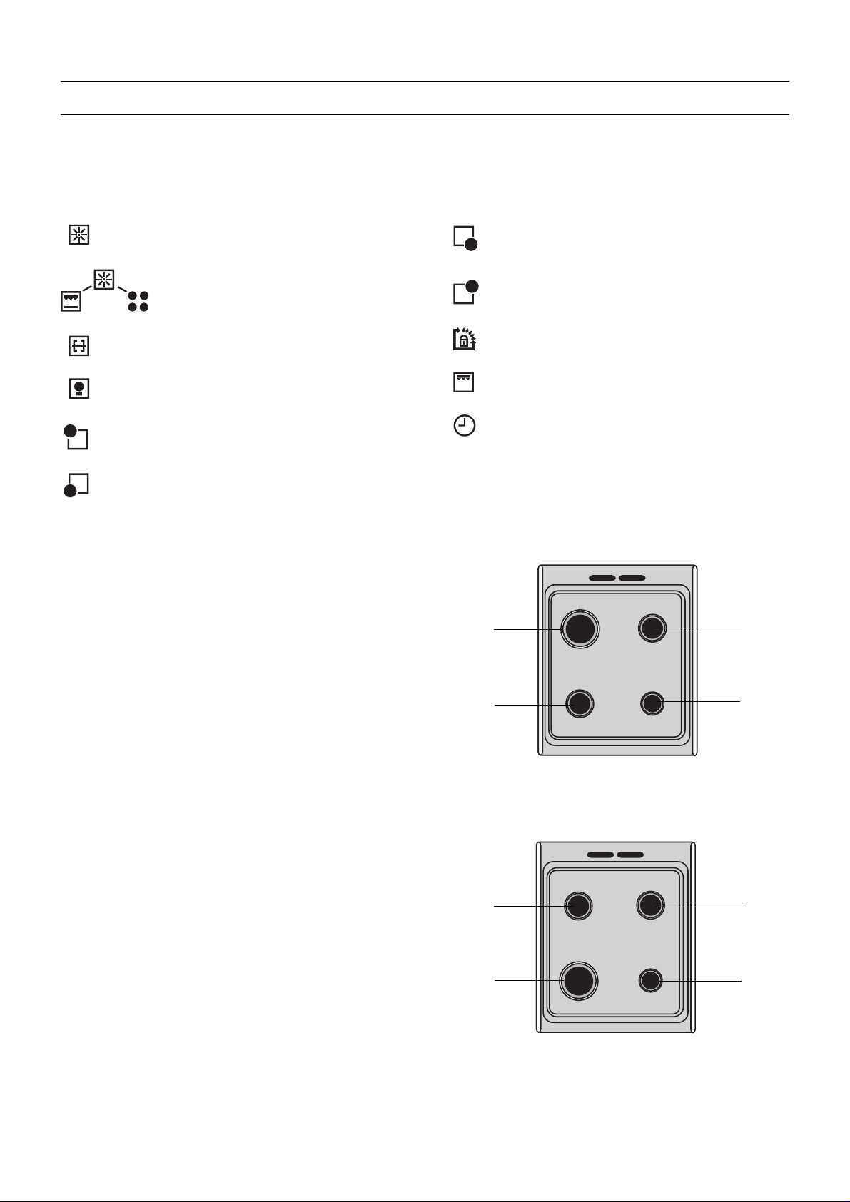
3.2 Cooker Hob
Your Cooker Hob is equipped with progressively
diminishing burners.
These are characterised by their flexibility in regulation,
these allow you:
Right-Front Burner Control Knob
Right-Rear Burner Control Knob
Oven and Grill Control Knob
Grill Control Lamp
Audible Signal Timer
High-speed
burner
3,00 kW
Half-speed
burner
2,00 kW
Half-speed
burner
2,00 kW
Auxiliary
burner
1,00 kW
- to very easily obtain each of the cooking speeds
between full speed and reduced flow.
- to identify the position appropriate for each type
of cooking suited to your personal habits and
subsequently find this posHion without fumbling.
3.3 Lid
Before closing the lid, please wait for the upper part of the
hob to cool, in order to not damage the lid.
When the oven is being used, the lid should be in the
raised position.
82
Half-speed
burner
2,00 kW
High-speed
burner
3,00 kW
Mod. EK 5122
Half-speed
burner
2,00 kW
Auxiliary
burner
1,00 kW
Mod. EK 6121/3/5/7
Page 5
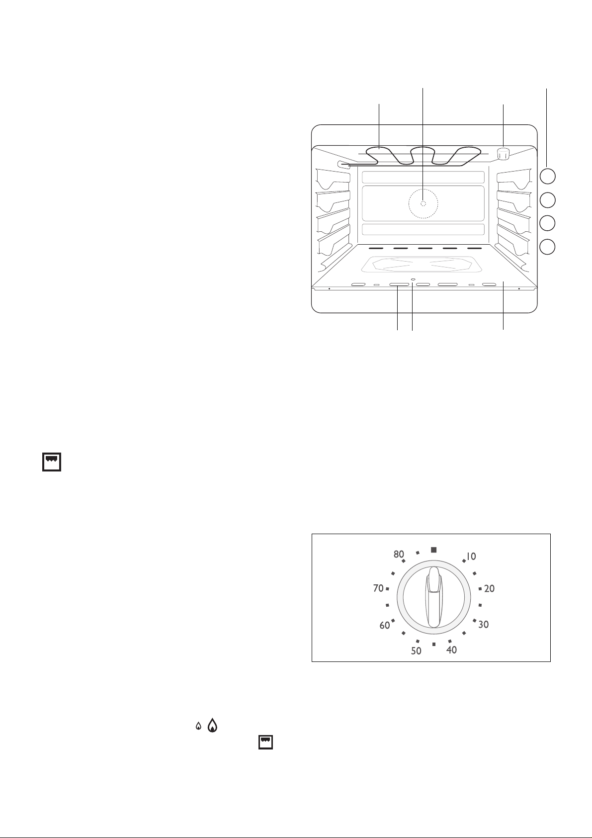
3.4 Oven
The Oven is fitted with a Gas Burner at sole plate level
and an Electrically Operated Grill in the oven roof. It can
be used for normal cooking, or as a grill. These two
modes of operation cannot be employed simultaneously.
● The Oven Burner is fitted with a Thermocouple-type
Safety Device. Should the flame be accidentally
extinguished (a violent draught, major spillage of
water or milk, etc.) a thermocouple safety device cuts
off the supply of gas to the Oven burner.
● In Standard Mode, there are 8 gradations of
adjustment level.
● In order to change from Standard Cooking to
GrillType Cooking, it is first necessary to extinguish
the Oven Burner, then to light the Grill.
● When cooking in the oven, please ensure that the
cooker lid is maintained in the open position in order
to avoid any risk of overheating.
3.5 Oven / Grill Control
This allows you to select the appropriate oven
temperature and to set the grill element in operation.
Rotating Spit
Motor Drive Orifice
Grill
Flame spy hole
Manual
ignition
orifice
Oven tray levels
Lamp
4
3
2
1
Oven
Sole
Plate
What the Symbols mean:
● OFF Position
1-8 Oven Temperature Setting
Grill Setting
3.6 Audible Signal Timer
This allows you to select a cooking time. After this period
of time has elapsed, the sounder rings, but does not halt
cooking.
● Set the Oven Control Knob to the OFF Position.
● For cooking times of less than 15 minutes, tum the
knob to a higher position, then bring it back to the
setting desired.
3.7 Indicator rings
The controls of your cooker are made up of an indicator
knob and an Indicator ring. The Indicator rings are
silkscreen printed:
The Hob Burner Indicator Ring: ●
The Oven Indicator Ring: ● 1 2 3 4 5 6 7 8
These graduations assist you in correctly reinstalling the
Indicator Rings following removal.
83
Page 6
3.8 Oven lllumination
This lights when the Oven lllumination Button is pressed.
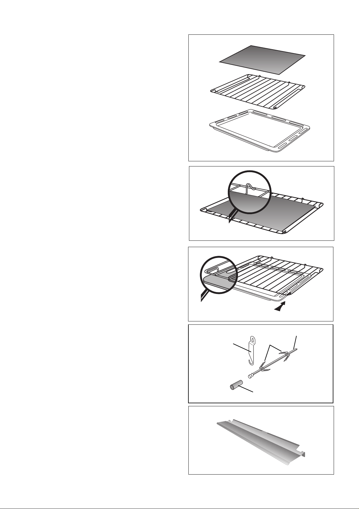
3.9 Oven Accessories
Your oven is equipped with the following:
1 Pastry Tray
1 Plate Support Grill
1 Drip Tray
1 Spit
The pastry laid either on the Pastry Tray, or on the Plate
Support Grill should not weigh any more than 7 to 8
kilograms.
The Pastry Tray
This is used for cooking or reheating Pizzas, small
individual pastries, laid directly on the Tray.
The Tray should be laid directly on the Tray Support Grid.
Special Oven Grid : Slide the Tray Support Grid into
the support slides, positioning the Pastry Tray stops
against the end of the oven (please, see the
illustration).
The Plate Support Grill
This is intended to support dishes (roasts, baked dishes,
pastry dishes or cake ffns, etc.) as well as grilled foods.
When you cook food directly on the grill, slide the drip tray
into the level 1 rails (the holes pointing towards the back
of the oven to allow air to circulate).
Special Oven Grid : slid the drip tray into the the rails
located under the Tray Support Grid (please see the
illustration).
The Drip Tray
This is used to collect the juices from grills.
It has not been designed to be used as a cooking dish.
When you are not using the Drip Tray, please ensure that
it is removed from the oven.
The Rotating Spit
This is composed of:
1 Spit
1 Removable Spit Handle
2 Spit Forks
1 Spit Support
Spit support
Spit
Forks
Removable spit
handle
Protective Screen
This is used while cooking with the grill. It protects the
Control Knobs from the heat given off.
84
Page 7
4. GUIDE IN USE
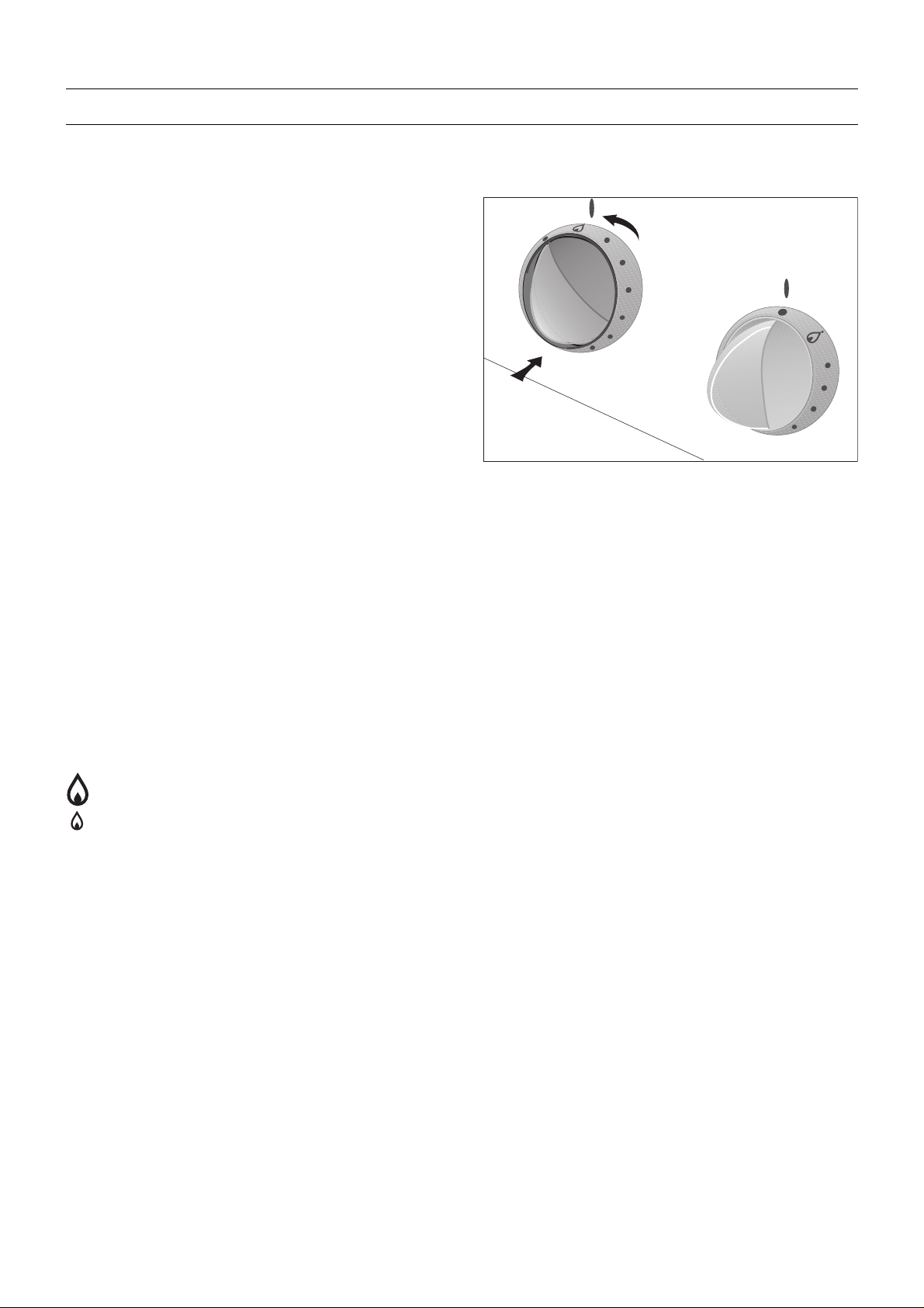
4.1 Lighting the Hob Burners
To light the Burners:
● Push the selected Control Knob inwards and turn it
anti-clockwise to its maximum setting keeping the
Control Knob pressed in.
● At the same time, press the electronic ignition button
so as to obtain sparks. K eep the button pressed until
a flame appears (sparks are produced approximately
once per second).
● Only for Mod. EK 6127 : Once a flame has
appeared, hold the Control Knob pressed in for
around 10 seconds so as to activate the Oven Saf ety
Device (Thermocouple).
When lighting the burners manually: Hold a flame
near the hob burner. Never turn the Control Knob
before approaching the burner with the flame.
To extinguish the burners:
● Turn the Control Knob clockwise to the stop, at the
OFF position.
The Main Settings Used:
•
Minimum setting
OFF position
Maximum setting
85
Page 8
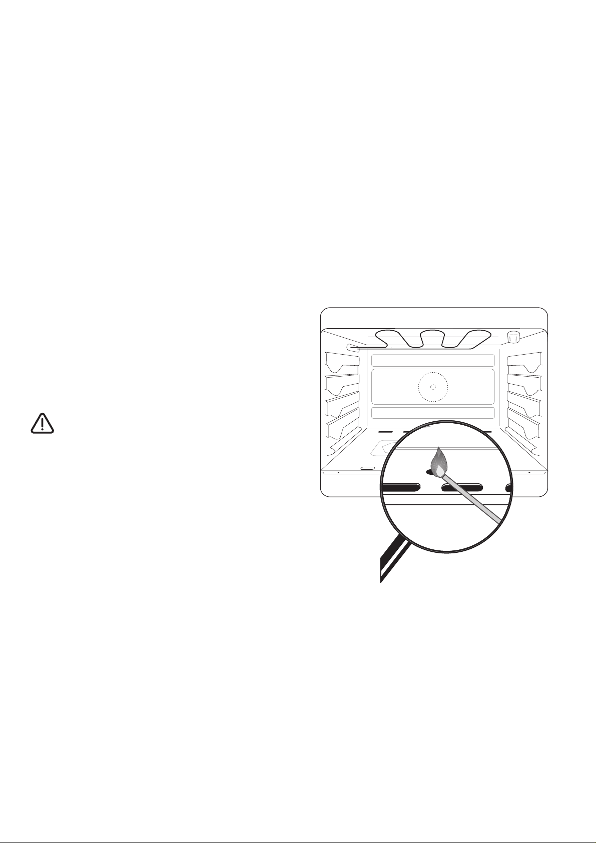
4.2 Lighting the Oven Burners
● Push the Oven/Grill Control Knob inwards and turn
it anti-clockwise to its maximum setting keeping the
Control Knob pressed in.
● At the same time, press the electronic ignition button
so as to obtain sparks. Keep the button pressed until
a flame appears (sparks are produced approximately
once per second).
● Once a flame has appeared, hold the Control Knob
pressed in for around 10 seconds so as to activate
the Oven Safety Device (Thermocouple).
● Should the bumer extinguish, repeat the operation,
maintaining the Control Knob pressed for 15
seconds, maximum.
● Check that there is a flame via the inspection orifice
at the front of the sole plate.
● Now adjust the Control Knob to the setting desired.
When lighting the oven manually: Hold a flame near
the oven ignition orifice, as shown in the illustration.
Never turn the Control Knob before approaching the
burner with the flame.
IMPORTANT:
Should the oven burner be accidentally
extinguished, turn the Control Knob to the OFF
position. Then wait 1 or 2 minutes before again
attempting to ignite it.
86
Page 9

4.3 Using the Grill
PLEASE T AKE CARE:
The accessible parts of the cooker can
become hot when using the grill. Please keep
children well away.
The Grill is used with the door partly open. In
addition, it is necessary to put the Screen
protecting the Gas Knobs in position.
The grill is intended to grill those pieces of meat (Rib of
Beef, Rib of Pork, etc.) which remain tender, to brown
toasts, or to brown pre-cooked foods, preferably still
warm (gratins - macaroni cheese, etc.).
Positioning the Protective Screen
● Open the Oven Door
● Hold the Protective Screen, with the small fold at
the side of the oven cavity (Fig. A )
● Hook the Protective Screen on the recess on the
oven cavity frame (Fig. B)
● Close the oven door again, leaving it slightly open,
the door should not touch the screen (Fig. C)
Removing the Protective Screen
A
B
● Open the Oven Door
● Slightly lift the front of the screen and disengage it
from the oven face.
Both during use and after using the grill, the
Protective Screen becomes hot.
In order to select the grill function, push and turn the
Oven/Grill Control Knob clockwise until it points to the
setting.
If you are cooking directly off the grill (grills), you should
slide the Drip Tray into the grid rails.
The Grill Warning Lamp
Located on the right of the Control Panel, this Warning
Lamp lights when the grill element is in operation.
C
87
Page 10

5. ADVICE ON HOW TO USE YOUR COOKER
5.1 Cooking on the Hob
Burners
Choosing Utensils
Always choose a utensil properly proportioned to the
diameter of the burner being used.
● 12 to 22 cm (5 to 9 inches) in diameter for the Medium
Speed Burners, located at the left- and rightrear
positions.
● 16 to 26 cm (6 to 10 inches) in diameter for the
HighSpeed Burner, located at the front-left position.
● 8 to 16 cm (3 to 61/2 inches) in diameter for the
Auxiliary Burner, at the front-right position.
When you have to use a utensil with a wide base
(Steriliser, Boiler, Preserving Pan, Couscous Steamer,
etc.). position it so that it is slightly displaced towards the
rear of the Hob, in orderthatthe base of the utensil does
not protrude over the front edge of the Enamelled Hob.
This will avoid the flame spilling over and overheating the
control panel.
Correct Burner matching
Poor burner matching
(energy is wasted)
For proper Burner Ignition
● Please ensure that you keep the burner rings
scrupulously clean. Any dirt on these could be the
cause of poor ignition.
● If you dismantle a burner for cleaning, before
attempting to light it please ensure that:
- the burner rings are sitting in a stable position on
the burners, and
- that the bumer crowns are in place.
Before closing the lid, please ensure that the
upper part of the hob has cooled, in order to
not damage the lid.
88
Page 11

5.2 Cooking in the Oven
Preheating should be carried out with the knob in the
position selected for cooking:
- around 8 minutes for positions 1 to 5
- around 15 minutes for positions 6 to 8
For dishes prepared in advance, both reheating and
defreezing should be carried out at the standard cooker
setting.
Our Advice
● The thickness, conductivity and the colour of the
cooking utensil can each influence the cooking
results.
● In order to take account of anything projecting widely ,
for roasts, you should use utensils with high sides,
in proportion to the joint to be roasted.
● Prick the skins of fowl and sausages with a fork
before cooking. Doing this will prevent the skin
ballooning up and bursting.
● During cooking, certain dishes inflate or rise.
Consequently, you should choose a cake tin or
soume mould that will leave one third free abov e the
raw preparation,
● Fire-proof glass dishes should be reserved for
cheese-topped dishes - gratins and souffles.
● Add the fat or oil just before the end of the cooking
period.
The influence of the cooking utensil on
the cooking results
You should be aware that:
A Aluminium, earthenware dishes, oven-prool
dishware, diminish the colour of the lower part of
the dish and conserve moisture in the food. We
advise their use for soft pastry, cooking cheese
(topped) dishes and roasts.
B Enamelled cast cookware, tin-plate, glass and
fireproof porcelain, dishes with a non-stick inner
surface and a coloured outer surface, will increase
the colouring of the lower part of the dish and tend
to dry out the food.We advise their use for tarts, pies,
quiches and any crusty dishes which should be
browned as much below as above.
You find that What shall I do ?
The lower part is too light Use an utensil
The dish is insufficiently of type B
cooked
The crust is too brown or
position the untensil
one slot lower
The lower part is too brown Use an utensil
Over-cooked of type A
The crust is too light
or
● A sheet of aluminium foil interposed between the
dish and the grill support will protect the sole plate
should anything overflo w. This sheet of f oil does not
need to cover the whole grill surface.
Never place aluminium foil directly in contact
with the sole plate since this could damage
the enamel.
When the oven is being used, the lid should
be in the raised position.
position the untensil
one slot higher
89
Page 12

5.3 Cooking with the Grill
Cooking is a radiant heat process. Only the grill element
in the roof is heated. This cooking method is used to grill
pieces of meat (rib of beef, pork rib, etc.) which remain
tender, to brown toasts, or pre-cooked foods, preferably
still warm (gratins- macaroni cheese, etc.).
Whenever you are cooking with the grill on, /;\
this must be done under your direct
supervision, with the oven door partly open,
the protective screen in position and the lid
raised.
Grills
● Prepare the item to be grilled, lightly grease it on
both sides.
● Place it directly on the dish support grid.
● Install the protective screen.
4
3
1
● Set the oven/grill Control Knob to the position.
● Slide the drip tray into the dish support grid rails.
● Slide these into either slot 3 or slot 4, depending on
the thickness of the food to be cooked.
● Slot 3 is to be preferred for thinner pieces of food
(toasts, pork ribs, sausages, smaller fish, etc.).
● Slot 4 is to be preferred for thicker pieces of food
(rib of beef, larger fish, chicken pieces).
● When the first side is browned, turn it over, without
pricking it, so as not to lose the juices.
● Grill the second side.
● Add salt when cooking is finished.
● Cooking time is deterrnined in relationship to
thickness rather than by weight.
Cheese topped dishes
4
3
● Install the protective screen.
● Set the oven/grill Control Knob to the position.
● Place the dish directly on the dish support grill and
slide the whole into either slot 3 or slot 4.
● Leave the dish under the radiation from the grill for
several minutes.
90
Page 13

5.4 Cooking with the Spit
● Screw the Removable Handle onto the Spit
● Slide the Fork onto the Spit, followed by the joint to
be roasted, taking care that it is properly centred.
● Slide the second Fork onto the Spit,
● Lock the forks in position with the screws.
● Fit the Spit support on the relevant hinge, as shown
in the diagram.
● Push the end of the spit into the square motor drive
hole (the orifice in the wall at the back of the oven)
and place the front of the spit on the relevant support,
as shown in the diagram.
● Unscrew the spit handle.
● Slide the dish support grill into slot 1, then place the
drip tray on top.
● Install the protective screen.
● Close the door, leaving it slightly ajar.
● Set the oven/grill Control Knob to the position.
● Press the button.
● Check that the spit is turning.
To remove the spit roast:
● Switch off the grill.
● Stop the spit by pressing the button.
● Remove the protective screen.
● Screw the Removable Handle onto the Spit
● Remove the spit from the oven.
● Remove the spit support.
Both during use and after using the grill, the
Protective Screen becomes hot.
91
91
Page 14

6. COOKING GUIDE
6.1 A Guide to Cooking in the Oven
The cooking times are approximate and can be varied in accordance with your cooking preferences.
The oven should be pre-heated. This should be done at the position selected for cooking
Preheating times : 8 minutes for positions 1 to 5
15 minutes for positions 6 to 8.
Dish Thermostat Runner Cooking time
Position
MEATS
Beef 6 - 7 2 15 min / 500 g
Leg of lamb 6 - 7 2 15 min / 500 g
Pork 4 - 5 3 35 min / 500 g
Veal 4 - 5 3 35 min / 500 g
Poultry 4 - 5 2 25 to 35 min for 500 g according to thickness
FISH
Large fish 4 - 6 2 25 - 35 min
Small fish, slices and filets 4 - 6 2 20 - 30 min
VEGETABLES
Potatoes "au g ratin" 5 - 7 2 60 - 70 min
Stuffes tomatoes 5 - 7 2 60 - 70 min
STARTERS
Falky pastries 6 - 7 2 20 - 30 min
Pâtés with crust 4 - 5 2 90 - 100 min in a bain-marie
Pizza 5 - 6 2 20 - 30 min
Quiche lorraines 5 - 7 2 - 3 40 - 45 min
Cheese Soufflés 5 - 7 2 40 - 50 min
PASTRIES
Savoy biscuits 3 - 4 3 35 - 45 min
Individual brioches cakes 4 - 5 2 20 - 30 min
Fruit cake 3 - 4 2 50 - 55 min
Sponge cakes 3 - 4 330 - 40 min
Kugelhopfs or brioches in tin 4 - 5 2 25 - 35 min
Macaroons 3 - 4 3 20 - 30 min
Short pastry (not filled) 5 2 20 - 30 min
Puff pastry 5 - 6 2 - 3 40 - 50 min
Pound cake 3 - 4 3 35 - 45 min
Short biscuits 3 - 4 3 20 - 30 min
Fruit pies (short pastry) 5 - 7 2 - 3 40 - 45 min
Fruit pies (flakypastry) 4 - 5 2 35 - 40 min
92
Page 15

6.2 Cooking chart for Grill dishes
Dish Thermostat Runner Cooking time
Position
GRILLED FOOD
Pork ribs 4 10 min per side
Rib of beef 3 20 min per side
Sausages - Merguezes 4 10 - 15 min
Fish 3 - 4 10 - 15 min depending on size and thickness
Chicken pieces 3 20 min per side
Chicken on the spit 50 - 70 min depending on size
BROWING AND CHEESE DISHES
Heated Dishes 3 5 - 10 min
Macaroni Cheese 3 5 - 10 min
Meringue T art 3 5 min
Toasted sandwiches 4 5 min
Crème brulée 3 5 min
The Grill should be used with the door partly open. In addition, it is also necessary to place the protection screen
for the Cooker Knobs in position.
Temperatures approximating to the Thermostat Settings
12345678
150°C 155°C 160°C 180°C 200°C 220°C 240°C MAX
93
Page 16

7. CLEANING
7.1 Cleaning the Hob
Before starting to clean your cooker, please check that
each of the Control Knobs is set to the OFF position and
you should wait for the cooker to cool.
Cleaning the Lid:
This should be cleaned with a wet sponge and a mild
detergent, then rinsed and dried.
The Enamelled Grills:
These should be washed in hot water with some mild
detergent, then rinsed and dried.
Burners (Crowns and Rings):
The Crowns should be washed in hot water with some
mild detergent. Please ensure that the burner rings are
kept scrupulously clean. Any dirt on these could be the
cause of poor ignition.
When you dismantle the burner rings for cleaning, before
again attempting to ignite the gas, please ensure that
both the burner rings and the bumer crowns are properly
positioned and dry.
The upper part of the Cooker Hob
Each time this is used, it should be wiped with a sponge
moistened with luke-warm water with a mild detergent.
You should avoid allowing anything to drip into the Hob
orifices.
Then it should be rinsed and dried with a soft cloth.
Where spills have occurred, moisten and allow to soak,
but these should never be scraped, nor should any
abrasive product be used, since this could scratch and
damage the enamelled surface.
The Control Panel and the Control Knobs:
For this, a sponge slightly moistened with soapy water
should be used. Then, carefully rinse and dry.
Oven Door, Drawer and Sides:
7.2 Cleaning of the oven with
enamel coating
Principle:
Cleaning of the smooth and shiny enamel oven walls
should be done manually.
Regular maintenance:
After preparing meat dishes, the oven walls should be
cleaned by means of a sponge and a detergent in order
to remove possible fat splashes. By doing so, the oven
will produce less steam when using it the next bme and
it will remain clean for a longer period. Soils from
overboiling on the bottom plate can be eliminated more
easily if the bottom plate is removed from the oven.
Long-term maintenance:
Use only appropriate products available on the market.
7.3 Cleaning the Catalytic
Enamel Oven
The principles
All the walls of your oven (except the sole plate) are
coated with a special (porous) enamel. This can be
recognised by its matt appearance and it being rough to
the touch.
This surface absorbs and destroys grease splashes
under the action of heat.
Maintenance
When cooking gives rise to a great deal of grease
splashing (fowl, grills, etc.), either the cooking period or
the temperature could be insufficient to eliminate all
these greases. When this occurs, after cooking, set the
Control Knob to its maximum setting then allow to heat,
with the oven emptied of all the accessories, for 45
minutes, then posHion the Control Knob to for a
further 5 minutes.
When this operation is started with the oven already cold,
the cleaning process will take 60 minutes.
Never spray cleaning products onto any sur~aces
coated with catalytic enamel.
Use a wet sponge with a mild detergent. Rinse and dry
carefully. Never use any abrasive products.
94
The oven walls become hotter than normal
during the cleaning sequence. Please keep
young children well away. Never use the Hob
burners during the cleaning sequence.
The sole plate is coated with a vitreous enamel, brilliant
and smooth to the touch. For this, manual cleaning is
necessary. When spills occur on the sole plate, remove
it for ease of cleaning with a sponge and a mild detergent.
Page 17

8. WHERE A FA ULT OCCURS, WHAT DO I DO ?
We most strongly reccommend that the following checks are made before calling a technician from the After Sales
Service. It is quite possible that the problem is simple to correct and you can solve it yourself.
ANOMALY
• Non of the burners will ignite.
• UOne of the Hob buners or the
Oven burner will not ignite.
• The results of ov en cookings are
unsatisfactory .
POSSIBLE CAUSES
• The main gas tap is off.
• The gas supply is obstructed.
• There is no more gas (individual
installation).
• The Hob burner or the Oven
burner is uncorrectly positioned.
• There is water in the Hob burner.
• The electronic ignition spark plug
is either wet or dirty
• Insufficient preheating.
• The thermostat is uncorrectly set.
• Either the cooking time or the
cooking utensil are unsuitable.
QUE FAIRE ?
• Open the gas supply.
• Check the consditions of the gas
pipe.
• Either change the cylinder or
check the level in the gas tank.
• Reinstall the Burner Assembly.
• Carefully wipe.
• Carefully clean and wipe it.
• Please consult the cooking
guide in this manual.
• The oven smokes.
• The Grill does not work.
If, after having checked all these different points, the fault persists, please contact your After Sales Service..
• The oven is dirty.
• Food is spilling over.
• The food (meat) is spilling heavily.
• The power is off.
• The cooker is unplugged.
• You should clean the Oven when
finished cooking (Please, see
the chapter on cleaning)
• Use a bigger utensil.
• Reduce the thermostat setting.
• Please, consult the Cooking
Guide.
• Check the Fuses and the Pwer
socket.
• Reconnnect the cooker
95
Page 18

9. IDENTIFICATION PLATE
The identification plate can be seen when the oven door
is opened.
The information carried by this plate will be required
when calling the After Sales Service or when ordering
spare parts.
Mod.
PROD. NO.
SER. NO.
MOD.
PROD. NO.
TYPE
SER. NO.
96
Page 19

PART INTENDED FOR THE INSTALLER
1. SAFETY INSTRUCTIONS FOR INSTALLATION
● Prior to installing, please ensure that the local gas
distribution characteristics (type of gas and pressure)
and the regulation of the cooker are compatible.
● This cooker must only be installed in a room having
adequate aeration.
● The regulation parameters for this cooker are carried
on the identification plate.
● This cooker is not to be connected to any device
evacuating the products of combustion. It must be
installed and connected in accordance with the
Installation Regulations currently in force. Special
attention shouW be paid to any provisions relating
to ventilabon.
● The Clean Air Flow required is 28 cu.m/h
● The walls adjacent to the cooker must either be
constructed of materials resistant to heat, or lined
with a material of this type.
● This cooker is rated as type X equipment, i.e. the
kitchen units abufflng the cooker shall not exceed
the cooker height. This Regulation ensures the
protection of such kitchen units.
● Install a main gas tap in a position that is both visible
and easily accessible.
● Should you use a flexib le gas supply pipe, it should
be accessible over its entire length and not be routed
behind the cooker.
● We recommend that flexible supply pipes be
changed well before the e xpiry date indicated on the
tube.
Both the installation and all maintenance shall be carried
out by a professional qualified in compliance with the
Regulations and Professional Rules currently in force:
NBND 51003.
For equipment connected to the Public Electricity Supply:
Standard NBN.
We cannot be held responsible where an
accident or incident occurs due to the lack of
an Earth (Ground) connection, or this is faulty .
Electrical Connections:
Please check that:
- the installation power rating is adequate.
- that the supply lines are in good condition.
- that the conductor diameters comply with the
Installation Regulations.
- that the fixed installation includes a device with single
pole disconnection contacts having a contact
opening distance of at least 3 mm.
Connection to a Gas Supply:
Please check that:
- the meter flow rating and the supply-pipe diameters
are sufficient to supply all the equipment installed.
- that all fittings are fully gas-tight.
97
Page 20

2. INST ALLING THE UNIT
2.1 Installing the Unit in
Position
The installation position
Your cooker should be installed as illustrated by the
figures opposite and the minimum distances indicated in
the sketches, between the cooker and the adjacent walls
of any kitchen units should be complied with (Fig.1).
Levelling and height adjustment
Your cooker is fitted with 4 adjustable feet allowing
proper height adjustment and levelling, as well as the
adjustment of the cooker lid to the adjacent kitchen units.
A No. 35 open-ended spanner should be used to screw
home or unscrew the feet.
2.2 Gas Connection
Your cooker as delivered is intended to operate on the
type of fuel indicated on the identification plate.
It can become necessary to change from one type of gas
to another. In such cases please refer to the Chapter
enttiled "Changing Gas".
Important:
20 mm
Class 1
Isolated unit
787
787
20 mm
Fig. 1
400
604
G10
400
604
G10
For proper functioning, reduced gas consumption and
extending the life of the cooker, please ensure that the
supply pressure corresponds with the values indicated in
Table No. 1.
Where the cooker is supplied with either Butane or
Propane, check that the pressure regulator regulates the
downstream gas pressure to 29 mbar for Butane and 37
mbar for Propane
98
Page 21

2.2.1 Choice of Supply pipe for an
isolated unit (Class 1)
a) Off the Public Gas Supply
Flexible Supply Pipe:
● A flexible pipe (with threaded ends) maximum length
1.50 m (Fig.2).
● We recommend the use of a flexib le pipe complying
with an appropriate Standard of a minimum length
of 1 m, the length of which should be chosen in
relationship to the actual position of the main gas
tap.
● Connect one end to the main gas tap before
positioning the cooker between the kitchen units,
connect the other end to the Cooker gas connection
extension using a gasket joint.
Fig. 2
● Install the cooker, checking that the loop formed by
the flexible pipe spreads in the passage space behind
an adjacent kitchen unit.
Rigid Piping:
● A rigid pipe with a threaded end.
b) For Butane/Propane Gas from either a bottb or a
tank
● Use a flexible rubber pipe of a maximum length of
1.50 m and 6 mm inside diameter, fitted with a special
Butane Fitting (Fig.3).
● Ensure that it is inserted over an adequate length
and fix it with a pipe clamp.
2.2.2 For the purchase of piping
● Flexible Rubber Piping: this should comply with the
Standards currently in force.
● Flexible Piping: this should comply with Technical
Specification ARGB 03/80.
Flexible
Piping
Joint
Butane
Fitting
Flexible
Piping
Flexible
Piping
Fig. 3
Pipe
Clamp
● Rigid Piping: this should comply with Standard NBND
51003.
99
Page 22

2.3 Electrical Connection
2.4 Replacing the Oven Lamp
Important:
Do not neglect to connect the cooker to the Earth
(Ground), via a 2Pole + Earth (10/16A) socket, while
complying with the provisions of Standard NBN and to
the Regulations currently in force.
We cannot be held responsible where an accident or
incident occurs consequent on the lack of an Earth
(Ground) connection, or where this is faulty.
The cooker is fitted with a flexible supply cable with a plug
to allow connection to a Mains Supply Socket and is
intended to operate at 230 V - 50 Hz.
Fuse capacity: 16 Amps, maximum.
NOTE:
Check the Total Connection Power Rating on the
identification plate to establish the Fuse Current Rating
required.
For a fixed installabon, the connection to the mains
should be carried out via a single pole circuit-breaker,
having a contact opening distance of at least 3 mm.
The yellow/green Earth Connection (Ground) conductor
shall not be cut by the circuit-breaker.
The supply cable should be positioned so that at no point
its temperature shall exceed the ambient temperature by
50C°.
Disconnect the cooker from the supply before replacing
the bulb.
Unscrew the globe, then the light bulb and replace same
with an identical type rated for high temperature use
(300°C) having the following characteristics:
- Voltage: 230 V - 50 Hz
- Power: 1 5 W
- Socket type: E 14.
Screw back the globe.
Before commencing with the connection, you should
check that:
- both the fuse ratings and the domestic electrical
installation are capable of accepting the equipment
load (Please check the identification plate).
- either the electrical socket or the single pole
circuitbreaker used for the connection are easily
accessible once the cooker is installed.
Where the supply cable needs to be replaced, this shall
only be replaced by a repair organisation approved by
the manufacturer, since special tools are required. Cable
type H05RR-F should be used of a cross-sectional area
suitable for the current rating.
Important:
No matter what the method of connection, the
cooker unit shall be connected to Earth (Ground)
in compliance with the Regulations currently in
force.
100
Page 23

3. CHANGING THE GAS TYPE
In compliance with the Regulations currently in
force, gas conversion may only be carried out by a
specialist (eitherthe manufacturer or an After-Sales
Service).
In order to change to another type of gas, it is necessary
to :
● change the jets (Hob, Oven)
● adjust the reduced flow regulation (Hob, Oven)
● check the gas connection mode
3.1 Changing the Hob Burner
Jets
● Raise the lid.
● Remove the hob grids, the b urner crowns and rings.
Unscrew the jets with a 7 mm socket spanner and
replace with jets appropriate for the new gas supply
(Please see Table No. 1 )
Table n° 1
BURNERS
NORMAL REDUCED BUTANE/PROPANE
POWER POWER
NATURAL GAS
dm3/h 15°C
kW kW Jets g/h Jets G20 G25
20 mbar 25 mbar
AuxiliaiY (Ø 55 mm)
Semi-rapid (Ø 71 mm)
Rapid (Ø 102 mm)
1 0,3 50 72 70 95 111
2 0,4 71 145 96 190 221
3 - 2,8(**) 0,6 86 203 119 286 332
Oven 3 82 218 116 286 332
Supply Pressure nom. mbar(*) 29 20
min. mbar(*) 25 18
max. mbar(*) 35 25
(*) mbar = 10 mm of water
(**) butane/propane
Important: When the cooker is converted either to
Butane or to Propane, the corresponding label (G30)
located in the injector pouch should be stuck to the
cooker
Air Regulation for the Hob Burners is automatically set
by the injector and is not adjustable by any other means.
101
Page 24

3.2 Regulating the Hob Burners
Minimum Gas Flow
In order to adjust the Burner Minimum Gas Flows
● Light the burners at the maximum setting.
● Turn the Control Knob to the minimum setting.
● Remove all the Control Knobs (Fig. 4).
Fig. 4
● Remove the two screws under the panel.
● Remove the panel.
● The Minimum Flow Adjustment Screw f or eachburner
is located on the Gas Tap Casting (Fig. 5).
● Proceed, in accordance with the instructions set out
in Table No. 2.
Checking:
● Turn the control several times from the maximum
setting to the minimum in order to verify the stability
of the flame. Should a burner extinguish, slightly
unscrew the adjustment screw.
● Reinstall the Control Knobs.
3.3 Changing the Oven Burner
Jet
Adjustment screw
Butane/Propane
Screw the
adjustment screw
fully
anti-clockwise
Fig. 5
Adjustment screw
Table n°2
Natural Gas
Screw in or unscrew
the adjustment screw
until a very short
flame is obtained
Replacing the injector:
● Open the oven door
● Remove the ov en sole plate by sliding it towards y ou.
● Unscrew the screw maintaining the ov en burner (Fig.
6) in place.
● Remove the oven burner.
● Unscrew the jet located at the back of the oven with
a 7 mm pipe spanner (Fig. 7) and replace it with a jet
appropriate for the gas supply (Please see Table No.
1 ).
● Reinstall the burner carrying out the above operations
in a reverse order and replace the sole plate.
The Air Regulation for the Oven Burner is automatically
set by the injector and is not adjustable by any other
means.
Screw
Fig. 6
Fig. 7
102
Page 25

3.4 Regulating the Oven Burner
Table n°3
Minimum Gas Flow
To adjust the Minimum Oven Gas Flow, carry out the
screw adjustment (Fig. 8) in accordance with Table
No. 3.
Following any adjustment of this type, the constancy of
the flame should be checked:
● Light the Oven Burner at the maximum setting and
allow to heat up, with the oven door closed, for
approximately 15 minutes.
● Turn the Control Knob from the maximum to the
minimum setting.
● Open the door normally and check that there is still
a flame.
● Turn the Control Knob several times from the
maximum to the minimum setting.
● Open and close the Oven Door when the Control
Knob is at the minimum setting.
Butane/Propane
Screw the adjustment
screw fully home.
Natural Gas
Screw the adjustment
screw fully home, then
uscrew 1/2 to 3/4 of a
turn.
Adjustment screw
Fig. 8
● Should the burner extinguish, slightly unscrew the
adjustment screw.
103
 Loading...