

Page 1

i
I N F O
INSTRUCTION MANUAL
BUILT-IN HOB
Models: EHG678* • EHG978* • EHM684* • EHM984* • EHG977* • EHG983* • EHG682* • EHG982*
*Denotes colour: W=White, X=Stainless Steel
Page 2
1
I N S T R U C T I O N M A N U A L
Congratulations and thank you for choosing an Electrolux Product. We are sure you will find your new
cooktop a pleasure to use and a great asset to your cooking. Before you use the cooktop, we recommend
that you read through the whole user manual which provides the description of the cooktop and its
functions. To avoid the risks that are always present when you use a gas or electric appliance, it is important
that the cooktop is installed correctly and that you read the safety instructions carefully to avoid misuse and
hazards. For future reference, please store this booklet in a safe place.
G E N E R A L I N F O R M A T I O N
MODEL AND SERIAL NUMBERS
These are shown on the data plate which is located under the burner box at the front right.
CONVERSION FOR USE WITH A DIFFERENT GAS
This appliance is adjusted for use with the particular gas shown on the gas-type label. However, it can be
converted for use with other gases, please refer to conversion section of this booklet.
AEROSOL SPRAYS
Do not spray aerosols in the vicinity of this appliance while it is in operation as aerosols can contain
flammable propellants.
WARNINGS
• The appliance is not intended for use by young children or infirm persons without supervision
• Young children should be supervised to ensure that they do not play with the appliance
• A steam cleaner is not to be used
• For appliance with supply cord:
• If the supply cord is damaged, it must be replaced by the manufacturer or its service agent or a
similarly qualified person in order to avoid a hazard
• It is necessary to have plug accessible after installation
• This appliance must not be used as a space heater
• The use of a gas cooking appliance results in the production of heat and moisture in the room in which it
is installed. Ensure that the kitchen is well ventilated: keep natural ventilation holes open or install a
mechanical ventilation device (mechanical extractor hood).
• Prolonged intensive use of the appliance may call for additional ventilation, for example opening of a window,
or more effective ventilation, for example increasing the level of mechanical ventilation where present.
CONTROLS AND OPERATION
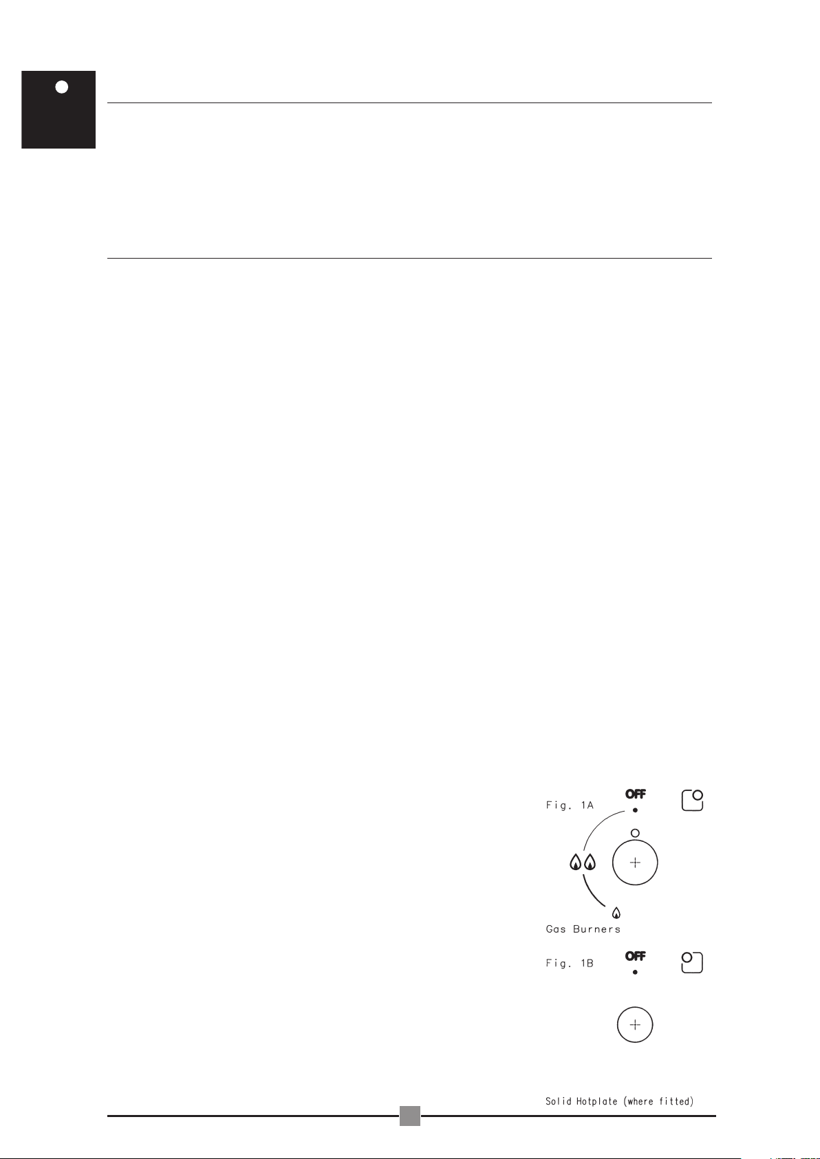
• Each burner is controlled by a valve which is activated by a control knob that diagrammatically shows
high to low (Fig 1A).
• Where a solid hotplate is fitted it is controlled by an infinite control knob which gives a range from high to
low using the numbers 6 to 1 as a guide (Fig 1B). This varies the amount of heat that the element delivers.
The control can be turned either clockwise or counter-clockwise to the desired position. There is a click
felt at the maximum point, number 6, to indicate high position.
LIGHTING BURNERS
These cooktops are fitted with battery or mains powered ignition. When the appliance has been connected and the
power is switched on, depressing any knob will release sparks to all burners. To
light a burner turn the corresponding knob to the ‘High’ position while depressing
the knob. For standard models the knob may be released once the flame is
established. For Flame Safeguard Models the knob must be held down for 5-10
seconds once the burner is ignited. If the flame goes out when the knob is
depressed simply depress the knob again and hold it down for the required
length of time. The height of the flame can be varied by turning the control knob
toward the ‘Low’ position. In the absence of electrical power, carry out the
ignition directly to the burner with a match or taper.
Caution:- In the event of the burner flame being accidentally
extinguished, turn off the burner control and do not attempt to
re-ignite the burner for at least 1 minute.
CHOICE OF BURNER
There are four burner sizes or three burners and an electric hotplate
(where fitted) for your convenience.
• A small burner for special low heat and slow cooking OR solid hotplate
(models with an electric element fitted).
• A medium burner for normal cooking and simmering.
• A large burner for fast heating and large utensils.
• A Wok burner for very fast heating using a Wok or large utensil.
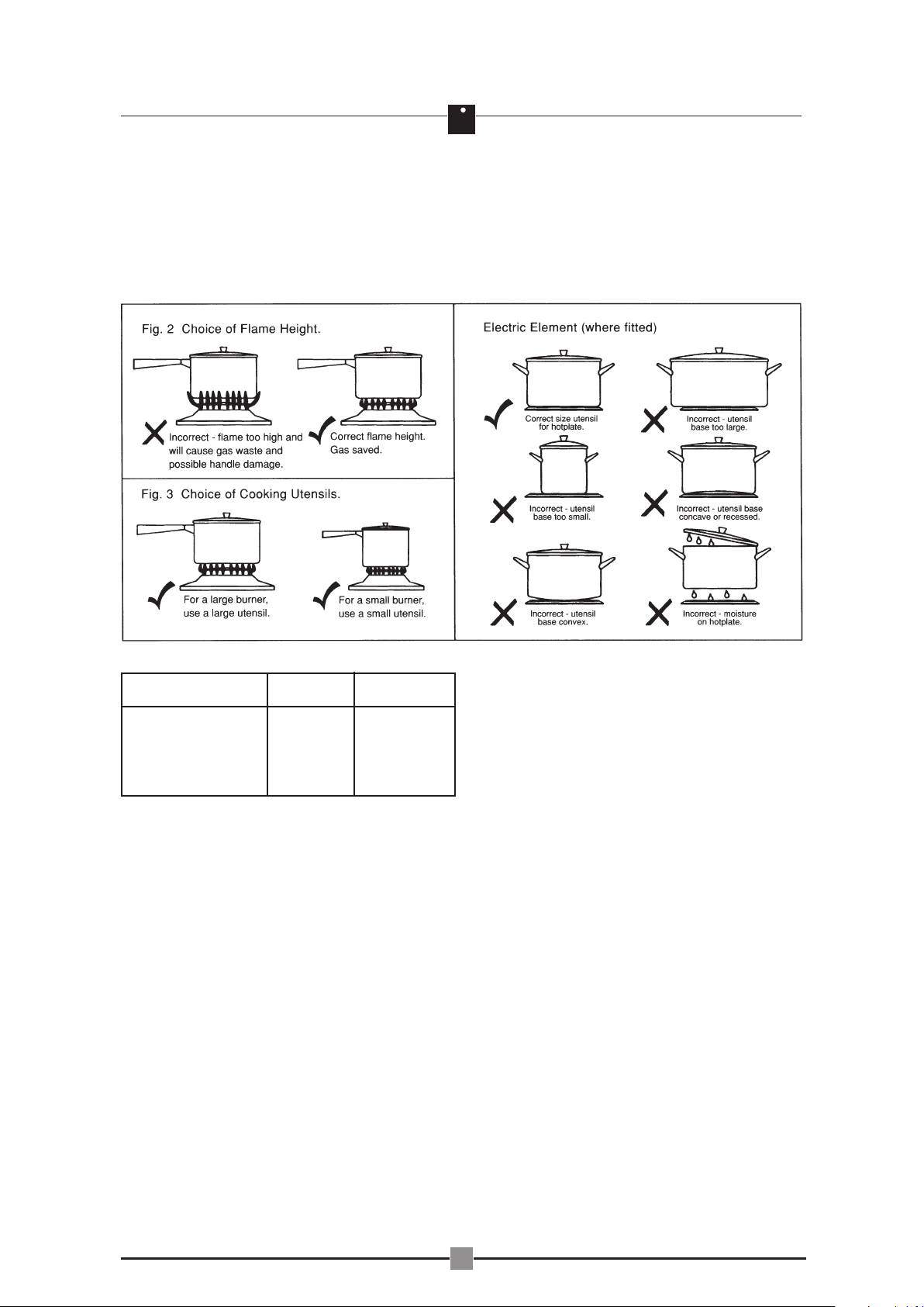
To conserve gas, place the pan centrally over the burner and adjust the
flame so that it does not extend past the edge of the pan (Fig. 2).
i
1
3
2
4
5
6
Page 3
i
2
Do not boil food too rapidly. A strong boil will not cook food any faster, and will waste energy.
UTENSILS
All normally available utensils; aluminium, stainless steel, cast iron, ceramic, etc., may be used on your new
gas or electric element model cooktop. Ensure that the utensils are steady and have flat bases to avoid
dangerous spill-over of hot liquids and wasted energy. Do not use hollow based or oversized utensils i.e.
utensils which have a greater diameter base than the hotplate (Fig. 3). Woks should only be used on the
wok burner and the wok support trivet.
C L E A N I N G A N D C A R E
ENAMEL
Persistent stains may require vigorous rubbing with nylon scourer or creamed powder cleansers. Household
enamel cleaners are available, follow the manufacturer’s instructions in their use. Harsh abrasive cleaners,
powder cleaners, steam cleaners, steel wool or wax polishes should not be used.
STAINLESS STEEL
All grades of stainless steel may stain, discolour or attain an adhering layer of grime in normal operation. To
achieve maximum surface appearance, stainless steel must be kept clean by regularly using the following
cleaning procedures, thus ensuring good performance and long service life. Wash with warm soapy water
and rinse with clean water. For an enhanced appearance wipe the surface with light oil (eg. sewing
machine), then wipe the surface dry with a soft, clean, lintless cloth, being sure to follow the polish or
brushing lines.
Where the stainless steel has become extremely dirty with signs of surface discolouration, (due to periods of
neglect or misuse) use a stainless steel cleaner. When removing these stains be sure to follow the polish or
brushing lines.
BURNER-CAPS AND CROWNS
These can all be lifted off and removed for separate cleaning. Ensure burner caps and crowns are
thoroughly dried after cleaning or spillage.
When cleaning the burner crowns, ensure that all the flame ports and other holes are free of any blockage.
If necessary, use a matchstick or brush to clear ports.
NOTE: When refitting the burner caps and crowns, ensure that they are correctly seated.
Burner minimum maximum
diameter diameter
Ultra-rapid
(Triple crown) 180 mm. 260 mm.
Large (rapid) 180 mm. 260 mm.
Medium (semi-rapid) 120 mm. 220 mm.
Small (Auxiliary) 80 mm. 160 mm.
UTENSIL SIZES
Page 4

SOLID HOTPLATE (Where fitted)
It is most important that the sealed
hotplate is kept clean and correctly
conditioned. If spillage occurs clean off
immediately after the hotplate has
cooled and warm hotplate for
approximately 30 seconds to dry
surface. At weekly intervals clean
hotplate with a nylon scouring pad and
soap. Use a damp cloth to wipe clean
and warm hotplate as described
previously.
Never use asbestos mats, wire mats or
grids, aluminium foil, woks or similar
utensils on the hotplate as it can lead to
overheating and permanent damage.
SERVICE
If a fault develops in your hotplate,
please check the points listed in Table
1.0 before calling for service as it may
be possible to avoid a service call and
therefore keep the appliance in use.
I N S T A L L A T I O N I N S T R U C T I O N S
This is a Category II, Class 3 appliance.
This appliance must be installed by an authorised person and in compliance with:
i. The local gas fitting regulations, municipal building codes, electrical wiring regulations and any other
relevant statutory regulations.
ii. The particular instructions as given below. Before commencing installation, check to ensure that the
appliance gas type given on label next to gas connection on appliance corresponds with the type of gas to
which it is intended the appliance be connected.
iii. This appliance is not connected to a combustion products evacuation device. It shall be installed and
connected in accordance with current installation regulations. Particular attention shall be given to the
relevant requirements regarding ventilation.
During installation the following points should be noted.
1. THE BENCH CUTOUT should be made as per ‘BENCH CUTOUT SIZE’ table (Fig. 4).
2. ADJACENT WALLS, CUPBOARDS AND PROTECTION FOR COMBUSTIBLE MATERIALS:
Ensure that overhead cupboards and any combustible material e.g. curtains are a minimum of 1000mm
from the cooktop. The minimum distance from exhaust fans is 750mm, the minimum distance from
rangehoods is 650mm and the minimum distance from the edge of the cooktop to any nearby wall should
be as specified in Fig.5. The distance between a rear or side wall can be reduced from 110mm and
210mm, providing the walls are covered with a non-combustible material, ie: Gib / Board (Fire line),
minimum thickness 19mm, covered with 5mm thick ceramic tiles, or sheet metal to a minimum height, not
less than 150mm. The surface temperature of a combustible surface must not exceed 50˚C above ambient
temperature.
3. PULL DOWN CLAMPS (four supplied) are supplied in a parts bag with their corresponding screws (four
supplied). To assemble attach the 4 clamps to each corner of the burner box via the screws provided.
When placing the appliance in the cutout, swing the clamps parallel with the box to avoid interference with
the cutout.
4. SAFETY BARRIER A barrier can be installed to prevent accidental contact with the cooktop base, where
the base of the cooktop is accessible from below (ie inside a cupboard, etc).
Impressions have been incorporated into the base to ensure a minimum clearance of 10mm is maintained
between the base and the barrier. This barrier may be made of any rigid material.
i
3
FAULT POSSIBLE CAUSE REMEDY
Burner will not light even though the Gas supply valve turned off. Turn on gas supply to
sparker is working. appliance.
Port blockage in ignition Ensure that ports in ignition
area. area both upper and lower
are clean and dry.
Sparking at wrong point Ensure that crown is seated
because of incorrectly fitted properly, so that the spark
burner crown. fires to the receiving point in
the burner crown.
No spark is obtained when control Electricity supply is Switch on electricity or
knob is activated. disconnected or switched off. check fuses.
Spark plug wet or dirty. Dry or clean spark plug.
Flames uneven or tending to lift. Flame ports blocked or wet. Clean or dry flame ports.
Flame not staying on when knob Knob not held down long Repeat lighting procedure
released. enough for flame safeguard.
and hold knob down for 5-10
seconds.
Dirt or spillage on flame Clean flame safeguard
safeguard sensor. sensor tip.
Electric element not working. Controls incorrectly set. Check that the controls are
set correctly.
Household fuse blown or Replace fuse/check supply.
power supply off.
Smoking hotplate. Hotplate cleaner is curing. The cleaner will cure and
there will be no more smoke.
Low heat, slow cooking. Incorrect cooking utensil Refer to Fig. 2,3.
being used.
Flame won’t turn down sufficiently. Incorrect injector or gas Contact installer.
control valve incorrectly
adjusted.
Benchtop overheating. Incorrect cooking utensil Check Fig.3 for correct
used. utensil to be used.
Seal not installed. Install seal .
Flame goes out on low setting. Gas pressure too low. Contact installer to correctly
adjust regulator.
Gas valve needs adjustment. Contact service to adjust
by-pass screw.
Yellow flame with Wok burner. Can be normal. If soot deposits are evident
on wok contact service to
reduce injector size.
Table 1.0 SERVICING INSTRUCTIONS
Page 5

i
4
When the appliance is in position swing the clamps
under the bench top and lightly tighten. (Fig. 6)
5. RUBBER SEAL This is to be applied around the
edge of the hob (Fig. 7) leaving a 400mm cutout on
a hidden edge of the unit. This gap is to allow air to
enter for ventilation. NOTE: the rubber seal has talc
powder applied to its surface which should be
wiped off with a damp cloth after the unit has been
installed.
GAS CONNECTION:
Cylinder or network connection must be carried out
according to the relevant local standards.
Flexible Connection.
The supply hose must be visible for its entire length
(max. one metre) and must be secured with a hose
clamp A (Fig. 8A). The hose shall be fitted in such a
way that it cannot come into contact with a moveable
part of the housing unit (eg. drawer) and does not
pass through any space susceptible to becoming
congested. The sealing washer must be fitted.
Rigid Connection.
Connect by using an iron or copper pipe, starting
from the threaded outlet of elbow B (Fig. 8B).
Include an accessible, demountable pipe union in
the connection.
Elbow Positioning.
It is possible to reposition the elbow if required by
loosening the locking nut and elbow by using two
spanners. Retighten the entire assembly after the
elbow has been repositioned.
ELECTRICAL CONNECTION:
Before installing this appliance, the flexible cord must be connected to an approved plug by an authorised
person. The connection of the appliance to mains is effected via a cable located underneath.
This appliance is fitted with an earth connection. This must be connected to a domestic earth. The domestic
power outlet should be located within 600mm of the flexible cord connection point (ref Fig. 4). Whenever
thesocket or the installation does not have available an earthing connection, such connection must be
provided according to the local standards.
APPLIANCE DIMENSIONS
MODEL A B C
Square Models 600 535 45
Rectangular Models 860 510 45
BENCH CUT-OUT SIZE
MODEL X Y
Square Models 570 490
Rectangular Models 830 470
*GAS & ELECTRIC CONNECTION POINT
NOTE: It will be necessary for Servicing
purposes to disconnect the electrical
power supply.
WEIGHT of the unit is printed on the
appliance identification label.
TESTING APPLIANCE OPERATION:
After installation, test the appliance and
ensure that it operates correctly before
handing it over to the customer. The
following procedure is recommended:
1. Turn on the gas and electricity supply
(if applicable) and attempt ignition. (For
correct procedure, refer to the OPERATING
INSTRUCTIONS). Note that the additional time
needs to be allowed for the initial lighting as
air has to be purged from the pipes.
BATTERY HOLDER INSTALLATION INSTRUCTIONS
COMPONENTS:
1. BATTERY HOLDER (212-2-78)
2. MOUNTING BRACKET (30-24-103)
3. PLASTIC NUT
4. BATTERY 1.5V (659-1-5)
5. SPRING
6. RETAINING CAP
7. 2 SCREWS (701-2-103)
INSTALLATION NOTES:
1. MOUNT THE BRACKET IN AN EASILY ACCESSIBLE
LOCATION UNDER THE BENCHTOP, USING THE TWO
SCREWS PROVIDED.
2. REMOVE THE CAP AND PLASTIC NUT FROM THE
BATTERY HOLDER.
3. PLACE THE THREADED END OF THE BATTERY HOLDER
THROUGH THE LARGE HOLE IN THE BRACKET.
4. SCREW THE PLASTIC NUT ONTO THE BATTERY HOLDER.
5. ENSURE THE BATTERY AND SPRING REMAIN IN THE
HOLDER AND SCREW THE RETAINING CAP ON.
CONNECTED TO
PRODUCT
Page 6

i
5
2. Observe the flame appearance on each
burner. If it is much larger or much smaller
than expected, the injector size requires
checking. If it is too soft or too sharp the
aeration setting may need adjustment. Where
a flame is unsatisfactory, refer to the
SERVICING INSTRUCTIONS and correct the
fault, if possible.
3. When all the foregoing is satisfactory,
check the turndown setting on each burner,
as this may need adjustment. Flame
safeguard models have a controlling screw in
the spindle. Standard models have a
controlling screw in the body of the valve.
Normally, this will have been correctly set at
the factory and should not require adjustment.
For more details, refer to the SERVICING
INSTRUCTIONS.
4. If the appliance cannot be adjusted to
perform safely, inform the customer of the
problem and affix an appropriate warning
notice to the appliance. If the fault appears to
be dangerous the appliance should be
disconnected. If a minor fault exists, the
customer may wish to use the appliance while
awaiting service. The customer should be
advised that, in the event of a fault, the
Electrolux local Service Organisation or the
retailer from whom the appliance was
purchased should be contacted.
5. When satisfied that the unit is operating
correctly, turn off and instruct the customer on
correct operation as outlined in this booklet.
Ask the customer to operate the controls to
ensure that the correct procedure is understood. Servicing must only be carried out by an authorised
service person. Injector sizes required for various gas types are shown in Table 2.0. The appliance inlet
pressure for each gas type is also shown.
To convert the appliance for use with Citigas follow the conversion procedure.
A Qualified Technician should carry out this procedure and use a Conversion Kit available from Electrolux
The Kit contains -
• One injector for each hotplate burner with the size indicated in the table.
• One aeration calibrator per hotplate burner.
• One wok injector.
• Data Label.
To carry out the conversion or to access components within the appliance for service follow these instructions.
Read all of these instructions before commencing.
Fig. 6
Hob
Benchtop
Clamp Screw
Rubber Seal
BURNER BOX
Page 7

i
6
CONVERSION PROCEDURE
1. Disconnect the appliance from main electrical power supply.
2. Lift off trivets, burner caps, burner crowns, and control knobs.
3. Remove the existing injectors and fit the injectors appropriate for the required gas type as specified in the
table.
4. Fit the Citigas aeration calibrators to the injectors. Aeration calibrators with the large opening must be
fitted to large burner and wok burner. Calibrators with small opening fit medium and small burner.
5. Any faulty or damaged components should be replaced at this point.
6. Adjust the burners to minimum. By turning the screw on the body of the gas control valve (Standard
models) or in the shaft of the gas control valve (Flame safeguard models) Fig.9., adjust the size of the flame
at minimum.
Ensure that the flame does not go out at minimum (Fig. 10).
7. Connect to the main electrical power supply.
8. Check that ignition is satisfactory for all burners.
9. Check proper operation of solid hotplate (if fitted).
10. Stick Citigas data label over LPG information. If the supply cord of this appliance is damaged, it must
only be repIaced by a repair shop appointed by the manufacturer, because special purpose tools are
required. Refer to the local service agency for the correct replacement part. (Part no. 215-2-59)
Any sealing shall be restored after the gas conversion operation.
Table 2.0
LPG (butane) Citigas Natural Gas
*Appliance
Operating
27.5 mbar 10.0 mbar 20.0 mbar
Pressure (p)
Injector Rating - grams/hr. Injector Rating - kW Injector Rating - kW
Size (kW) Size Size
Wok 1.00 290 (4.0) 4.00 4.0 1.50 4.2
Large 0.90 230 (3.2) 2.82 2.9 1.19 3.1
Medium 0.70 130 (1.8) 2.10 2.1 0.96 1.9
Small 0.55 90 (1.2) 1.42 1.1 0.70 1.0
Fig. 9
* Adjust pressure with appliance operating at approximately 50% of maximum kW
Page 8

7
P/No. 342-1-487 ECN 04A076G
MANUFACTURER:
Electrolux Home Products Pty Ltd
P.O. Box 21 Prospect
South Australia 5082
i
 Loading...