

Page 1

instruction booklet
GB
gas hob
EHG 6762
Page 2

2 electrolux
Page 3

electrolux 3
Welcome to the world of ElectroluxWelcome to the world of Electrolux
Welcome to the world of Electrolux
Welcome to the world of ElectroluxWelcome to the world of Electrolux
Thank you for choosing a first class product from Electrolux, which
hopefully will provide you with lots of pleasure in the future.
The Electrolux ambition is to offer a wide variety of quality products that
make your life more comfortable.
You find some examples on the cover in this manual. Please take a few
minutes to study this manual so that you can take advantage of the benefits
of your new machine.
We promise that it will provide a superior User Experience delivering
Ease-of-Mind.
Good luck!
Page 4

4 electrolux
ContentsContents
Contents
ContentsContents
Important Safety InformationImportant Safety Information
Important Safety Information
Important Safety InformationImportant Safety Information
Description of the Hobs......................................................................... 7
Instructions for the UserInstructions for the User
Instructions for the User
Instructions for the UserInstructions for the User
Operation ..............................................................................................8
Maintenance and Cleaning ................................................................. 11
Something Not Working? ....................................................................13
Guarantee/Customer Service ............................................................. 28
European Guarantee .......................................................................... 30
Instructions for the InstallerInstructions for the Installer
Instructions for the Installer
Instructions for the InstallerInstructions for the Installer
Engineer technical data....................................................................... 14
Important safety requirements ............................................................ 16
Installation ............................................................................................ 17
Gas Connection................................................................................... 18
Location ............................................................................................... 18
Fitting the Hob into the Worktop......................................................... 19
Building In ............................................................................................ 20
Building over a cupboard or drawer ..................................................20
Building over a kitchen unit with door .................................................20
Electrical Connections......................................................................... 21
Wiring diagram ...................................................................................22
Fault Finding ........................................................................................ 23
Commissioning.................................................................................... 26
Conversion from Natural Gas to LPG .................................................27
..................................................................................................................
.........................................................
..................................................................................................................
..................................................................................................................................
.................................................................
..................................................................................................................................
................................................................................................................
........................................................
................................................................................................................
1414
14
1414
55
5
55
88
8
88
Guide to Use the instructionsGuide to Use the instructions
Guide to Use the instructions
Guide to Use the instructionsGuide to Use the instructions
The following symbols will be found in the text to guide you throughout the Instructions:
Safety Instructions
!!
!
!!
"
MANUFACTURER:
ELECTROLUX HOME PRODUCTS ITALY S.P.A.
Viale Bologna, 298 - 47100 Forlì - (Italy)
Step by step instructions for an operation
Hints and Tips
Environmental information
Page 5

electrolux 5
Important Safety InformationImportant Safety Information
Important Safety Information
Important Safety InformationImportant Safety Information
YY
ou MUST rou MUST r
Y
ou MUST r
YY
ou MUST rou MUST r
using the hob. If you need assistance, contact our Customerusing the hob. If you need assistance, contact our Customer
using the hob. If you need assistance, contact our Customer
using the hob. If you need assistance, contact our Customerusing the hob. If you need assistance, contact our Customer
Care Department on 08705 950950Care Department on 08705 950950
Care Department on 08705 950950
Care Department on 08705 950950Care Department on 08705 950950
II
nstallationnstallation
I
nstallation
II
nstallationnstallation
# This appliance must be installed and serviced by a competent person as
ead these waread these war
ead these war
ead these waread these war
nings carnings car
nings car
nings carnings car
efully beforefully befor
efully befor
efully beforefully befor
e installing ore installing or
e installing or
e installing ore installing or
stated in the Gas Safety (Installation and Use) Regulations Current Editions
and the IEE Wiring Regulations.
# For appliances installed in the Republic of Ireland please refer to NSAI-
Domestic Gas Installations I.S.813 Current Editions and the ETCI Rules for
Electrical Installations.
# Remove all packaging before using the hob.
# Ensure that the gas and electrical supply complies with the type stated on
the rating plate, located near the gas supply pipe.
# Do not attempt to modify the hob in any way.
People People
People
People People
# This hob is designed to be operated by adults. Do not allow children to play
SafetySafety
Safety
SafetySafety
near or with the hob.
# This appliance is not intended for use by children or other persons whose
physical, sensory or mental capabilities or lack of experience and knowledge
prevents them from using the appliance safely without supervision or instruction
by a responsible person to ensure that they can use the appliance safely.
# The hob gets hot when it is in use. Children should be kept away until it has
cooled.
# Children can also injure themselves by pulling pans or pots off the hob.
During UseDuring Use
During Use
During UseDuring Use
# This hob is intended for domestic cooking only. It is not designed for
commercial or industrial purposes.
# This appliance is not connected to a combustion products evacuation device.
It must be installed and connected in accordance with current installation
regulations. Particular attention shall be given to the relevant requirements
regarding ventilation.
# When in use a gas cooking hob will produce heat and moisture in the room
in which it has been installed. Ensure there is a continuous air supply, keeping
air vents in good condition or installing a cooker hood with a venting hose.
# Ensure a good ventilation around the appliance. A poor air supply could cause
lack of oxygen.
Page 6

6 electrolux
# When using the hob for a long period time, the ventilation should be
improved, by opening a window or increasing the extractor speed.
# Do not use this hob if it is in contact with water. Do not operate the hob with
wet hands.
# Ensure the control knobs are in the ‘OFF’ position when not in use.
# When using other electrical appliances, ensure the cable does not come
into contact with the hot surfaces of the cooking appliance.
# Unstable or misshapen pans should not be used on the hob as unstable
pans can cause an accident by tipping or spillage.
# Never leave the hob unattended when cooking with oil and fats.
# Never use plastic or aluminium foil dishes on the hob.
# Perishable food, plastic items and areosols may be affected by heat and
should not be stored above or below the hob unit.
# This appliance cannot be cleaned with steam or with a steam cleaning
machine.
ServiceService
Service
ServiceService
# This hob should only be repaired or serviced by an authorised Service
Engineer and only genuine approved spare parts should be used.
Environmental InformationEnvironmental Information
Environmental Information
"
Environmental InformationEnvironmental Information
# After installation, please dispose of the packaging with due regard to
safety and the environment.
# When disposing of an old appliance, make it unusable, by cutting off the
cable.
# The symbol on the product or on its packaging indicates that this
product may not be treated as household waste. Instead it shall be handed
over to the applicable collection point for the recycling of electrical and
electronic equipment. By ensuring this product is disposed of correctly,
you will help prevent potential negative consequences for the environment
and human health, which could otherwise be caused by inappropriate
waste handling of this product. For more detailed information about
recycling of this product, please contact your local city office, your
household waste disposal service or the shop where you purchased the
product.
These instructions are only valid for countries whose identification symbols
are shown on the cover of this instruction booklet and on the appliance itself.
Keep this instruction book for future reference and ensure it isKeep this instruction book for future reference and ensure it is
Keep this instruction book for future reference and ensure it is
Keep this instruction book for future reference and ensure it isKeep this instruction book for future reference and ensure it is
passed on to any new ownerpassed on to any new owner
passed on to any new owner
passed on to any new ownerpassed on to any new owner
..
.
..
Page 7
Description of the HobDescription of the Hob
Description of the Hob
Description of the HobDescription of the Hob
3
2
1
6
electrolux 7
3
4
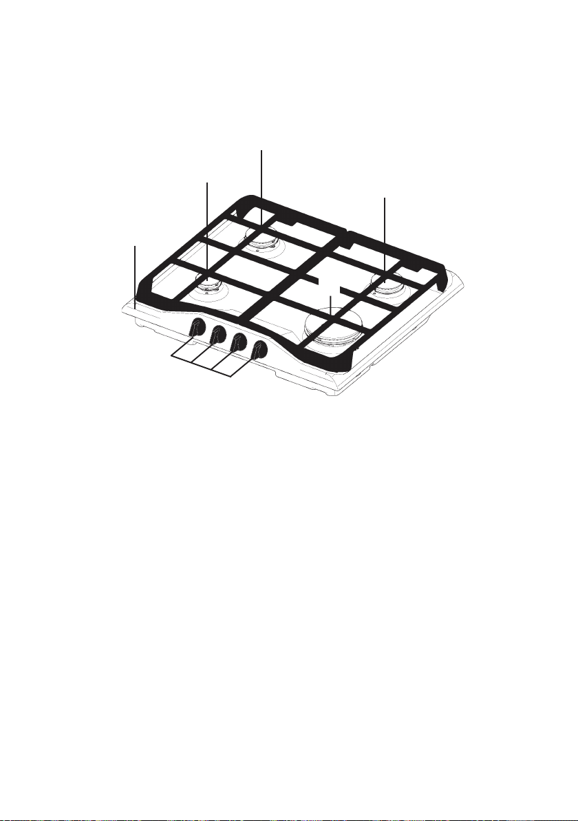
1. Hob Top
2. Auxiliary Burner
3. Semi-rapid Burner
4. Rapid Burner
5. Control knobs
Page 8
8 electrolux
Instructions for the UserInstructions for the User
Instructions for the User
Instructions for the UserInstructions for the User
INSTALLATION
Any gas installation must be carried out by a registeredAny gas installation must be carried out by a registered
Any gas installation must be carried out by a registered
Any gas installation must be carried out by a registeredAny gas installation must be carried out by a registered
competent person, and in accordance with existing rules andcompetent person, and in accordance with existing rules and
competent person, and in accordance with existing rules and
competent person, and in accordance with existing rules andcompetent person, and in accordance with existing rules and
regulations.regulations.
regulations.
regulations.regulations.
The relevant instructions are to be found in the second section of this
manual.
Please, ensure that, once the hob is installed, it is easily accessible for
the engineer in the event of a breakdown.
WHEN THE HOB IS FIRST INSTALLED
Once the hob has been installed, it is important to remove any protective
materials, which were put on in the factory.
The manufacturer will not accept liability, should the above instructions or
any of the other safety instructions incorporated in this book be ignored.
OperationOperation
Operation
OperationOperation
Lighting the burnersLighting the burners
Lighting the burners
Lighting the burnersLighting the burners
For easier lighting, proceed before putting a pan on the panFor easier lighting, proceed before putting a pan on the pan
For easier lighting, proceed before putting a pan on the pan
For easier lighting, proceed before putting a pan on the panFor easier lighting, proceed before putting a pan on the pan
support.support.
support.
support.support.
To light a burner:
!
# turn the relevant knob anti-clockwise to maximum
position, then push it down to ignite the burner.
# Upon ignition, keep the knob pushed down
about
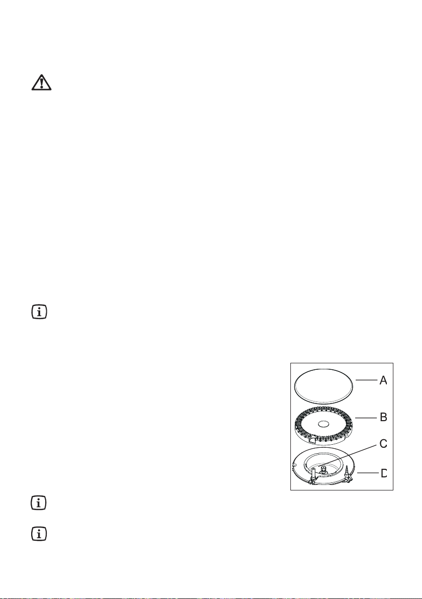
"thermocouple" (see the diagram - letter D) to
be heated and the safety device to be switched
off, otherwise the gas supply would be
interrupted.
# Then, check the flame is regular and adjust it as
required.
To put the flame out, turn the knob to the
symbol
If the burner does not ignite, turn the control knob
to zero, and try again.
5 seconds 5 seconds
5 seconds. This will allow the
5 seconds 5 seconds
#.
AA
A - Burner cap
AA
BB
B - Burner crown
BB
CC
C - Ignition electrode
CC
DD
D - Thermocouple
DD
Page 9
electrolux 9
If you cannot light the flame even after severalattempts, check the "cap"
(see the diagram - lett.
in the correct position.
Do not keep the control knob pressed for more than 15
seconds. If the burner does not light even after 15 seconds,
release the control knob, turn it the "off" position and wait for
at least one minute before trying to light the burner again.
When switching on the mains, after installation or a power cut, it is quite
normal for the spark generator to be activated automatically.
In the absence of electricityIn the absence of electricity
In the absence of electricity, ignition can occur without the electrical
In the absence of electricityIn the absence of electricity
device; in this case, approach the burner with a flame, push the relevant
knob down and turn it anti-clockwise until it reaches the maximum position.
If the control knobs become difficult to turn, please contact your local
Service Force Centre.
Using the hob correctlyUsing the hob correctly
Using the hob correctly
Using the hob correctlyUsing the hob correctly
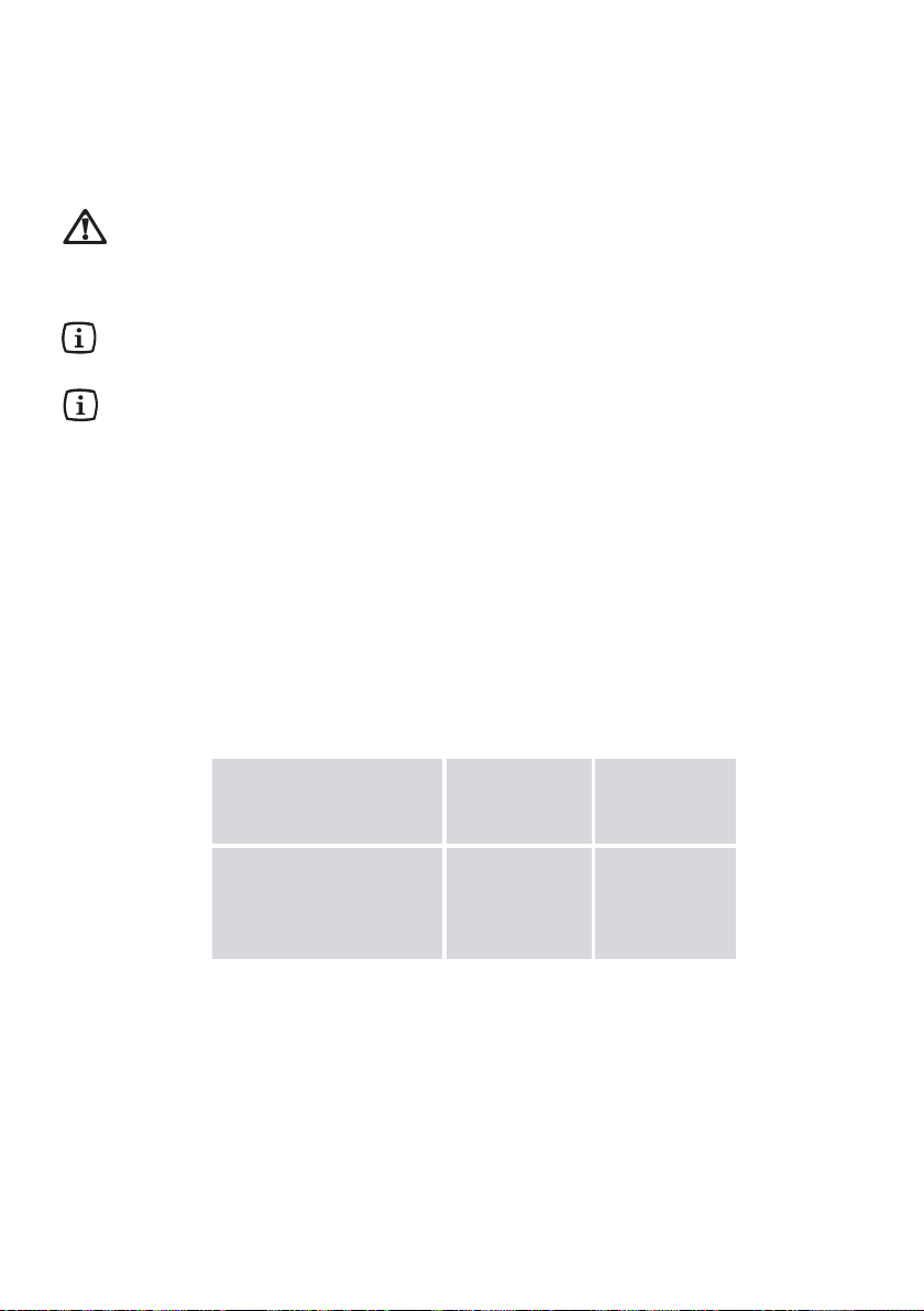
To ensure maximum burner efficiency, it is strongly recommended that you
use only pots and pans with a
so that flame will not spread beyond the bottom of the vessel (see the table
below).
AA
A) and the"crown" (see the diagram - lett.
AA
flat flat
flat bottom fitting the size of the burner used,
flat flat
BB
B) are
BB
BurnerBurner
Burner
BurnerBurner
Large (rapid) 180 mm 260 mm
Medium (semi-rapid) 120 mm 220 mm
Small (auxiliary) 80 mm 160 mm
minimumminimum
minimum
minimumminimum
diameterdiameter
diameter
diameterdiameter
maximummaximum
maximum
maximummaximum
diameterdiameter
diameter
diameterdiameter
Page 10
10 electrolux
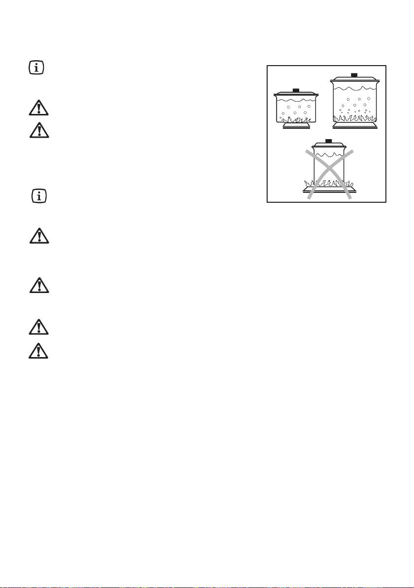
As soon as a liquid starts boiling, turn down
the flame so that it will barely keep the
liquid simmering.
Use only pans or pots with flatUse only pans or pots with flat
Use only pans or pots with flat
Use only pans or pots with flatUse only pans or pots with flat
bottom.bottom.
bottom.
bottom.bottom.
If you use a saucepan which is smallerIf you use a saucepan which is smaller
If you use a saucepan which is smaller
If you use a saucepan which is smallerIf you use a saucepan which is smaller
than the recommended size, thethan the recommended size, the
than the recommended size, the
than the recommended size, thethan the recommended size, the
flame will spread beyond the bottomflame will spread beyond the bottom
flame will spread beyond the bottom
flame will spread beyond the bottomflame will spread beyond the bottom
of the vessel, causing the handle toof the vessel, causing the handle to
of the vessel, causing the handle to
of the vessel, causing the handle toof the vessel, causing the handle to
overheat.overheat.
overheat.
overheat.overheat.
Carefully supervise cooking with
fat or oilfat or oil
fat or oil,
fat or oilfat or oil
since these types of foodstuff can result in
a fire, if over-heated.
The stainless steel can become tarnished if excessivelyThe stainless steel can become tarnished if excessively
The stainless steel can become tarnished if excessively
The stainless steel can become tarnished if excessivelyThe stainless steel can become tarnished if excessively
heated. Therefore prolonged cooking with potstones,heated. Therefore prolonged cooking with potstones,
heated. Therefore prolonged cooking with potstones,
heated. Therefore prolonged cooking with potstones,heated. Therefore prolonged cooking with potstones,
earthenware pans or cast-iron plates is inadvisable. Also,earthenware pans or cast-iron plates is inadvisable. Also,
earthenware pans or cast-iron plates is inadvisable. Also,
earthenware pans or cast-iron plates is inadvisable. Also,earthenware pans or cast-iron plates is inadvisable. Also,
do not use aluminium foil to protect the top during use.do not use aluminium foil to protect the top during use.
do not use aluminium foil to protect the top during use.
do not use aluminium foil to protect the top during use.do not use aluminium foil to protect the top during use.
Make sure pots do not protrude over the edges of the cooktopMake sure pots do not protrude over the edges of the cooktop
Make sure pots do not protrude over the edges of the cooktop
Make sure pots do not protrude over the edges of the cooktopMake sure pots do not protrude over the edges of the cooktop
and that they are centrally positioned on the rings in order toand that they are centrally positioned on the rings in order to
and that they are centrally positioned on the rings in order to
and that they are centrally positioned on the rings in order toand that they are centrally positioned on the rings in order to
obtain lower gas consumption.obtain lower gas consumption.
obtain lower gas consumption.
obtain lower gas consumption.obtain lower gas consumption.
Do not place unstable or deformed pots on the rings: theyDo not place unstable or deformed pots on the rings: they
Do not place unstable or deformed pots on the rings: they
Do not place unstable or deformed pots on the rings: theyDo not place unstable or deformed pots on the rings: they
could tip over or spill their contents, causing accidents.could tip over or spill their contents, causing accidents.
could tip over or spill their contents, causing accidents.
could tip over or spill their contents, causing accidents.could tip over or spill their contents, causing accidents.
Pots must not enter the control zone.Pots must not enter the control zone.
Pots must not enter the control zone.
Pots must not enter the control zone.Pots must not enter the control zone.
Page 11
Maintenance and CleaningMaintenance and Cleaning
Maintenance and Cleaning
Maintenance and CleaningMaintenance and Cleaning
Before any maintenance or cleaning can be carried out, youBefore any maintenance or cleaning can be carried out, you
Before any maintenance or cleaning can be carried out, you
Before any maintenance or cleaning can be carried out, youBefore any maintenance or cleaning can be carried out, you
must DISCONNECT the hob frmust DISCONNECT the hob fr
must DISCONNECT the hob fr
must DISCONNECT the hob frmust DISCONNECT the hob fr
The hob is best cleaned whilst it is still warm, as spillage canThe hob is best cleaned whilst it is still warm, as spillage can
The hob is best cleaned whilst it is still warm, as spillage can
The hob is best cleaned whilst it is still warm, as spillage canThe hob is best cleaned whilst it is still warm, as spillage can
be removed more easily than if it is left to cool.be removed more easily than if it is left to cool.
be removed more easily than if it is left to cool.
be removed more easily than if it is left to cool.be removed more easily than if it is left to cool.
This appliance cannot be cleaned with steam or with a steamThis appliance cannot be cleaned with steam or with a steam
This appliance cannot be cleaned with steam or with a steam
This appliance cannot be cleaned with steam or with a steamThis appliance cannot be cleaned with steam or with a steam
cleaning machine.cleaning machine.
cleaning machine.
cleaning machine.cleaning machine.
om the electricity supplyom the electricity supply
om the electricity supply
om the electricity supplyom the electricity supply
electrolux 11
..
.
..
The Hob TThe Hob T
The Hob T
The Hob TThe Hob T
Regularly wipe over the hob top using a soft cloth well wrung out in warm water to
which a little wasing up liquid has been added. Avoid the use of the following:
- household detergent and bleaches;
- impregnated pads unsuitable for non-stick saucepans;
- steel wool pads;
- bath/sink stain removers.
Should the hob top become heavily soiled, the following products are
recommended:
- For stainless steel hobs use a proprietary
stainless steel cleaner.
- For other hobs use Hob Brite or Bar Keepers
Friend.
Do not leave acid or alkalineDo not leave acid or alkaline
Do not leave acid or alkaline
Do not leave acid or alkalineDo not leave acid or alkaline
substances (e.g. vinegarsubstances (e.g. vinegar
substances (e.g. vinegar
substances (e.g. vinegarsubstances (e.g. vinegar
lemon juice, etc.) on the cooktop.lemon juice, etc.) on the cooktop.
lemon juice, etc.) on the cooktop.
lemon juice, etc.) on the cooktop.lemon juice, etc.) on the cooktop.
Cast iron Cast iron
Cast iron
Cast iron Cast iron
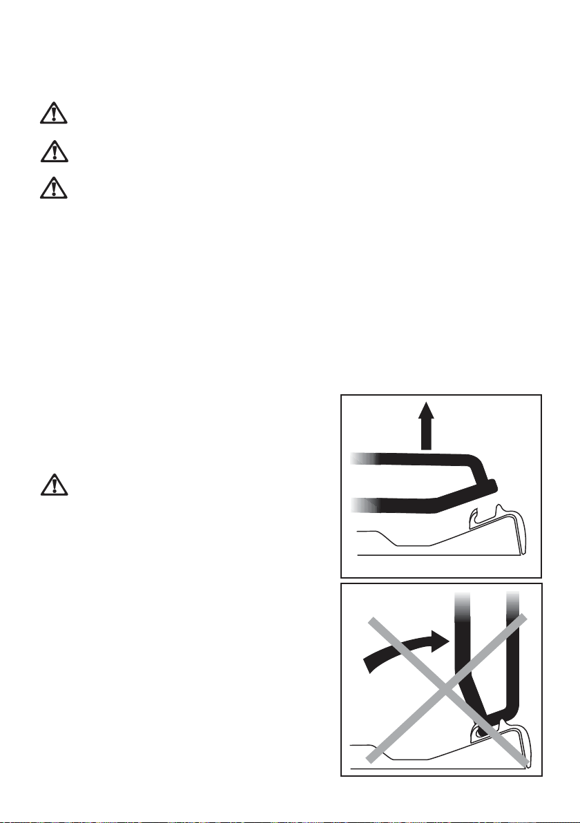
The hob has cast iron pan supports.
Take care when removing them. They
are very heavy and could damage the
hob or your kitchen furniture if you let
them fall down.
To keep the pan supports in the correct
position, they are hooked into hinges at the
back of the hob. When removing the pan
supports, lift them up as shown in the
diagram. Never turn the pan supports on
the hinges, this could damage them.
Wash the pan supports using hot soapy
water. If necessary, a paste cleaner or a
opop
op
opop
Pan SupportsPan Supports
Pan Supports
Pan SupportsPan Supports
, salt,, salt,
, salt,
, salt,, salt,
YES
NO
Page 12

12 electrolux
soap impregnated steel wool pad can be used with caution.
After cleaning, be sure to wipe dry with a soft cloth and make sure that the
pan supports are correctly positioned.
The BurnersThe Burners
The Burners
The BurnersThe Burners
The burner caps and crowns can be removed for cleaning.
Wash the burners caps and crowns using hot soapy water, and remove
marks with a mild paste cleaner. A well moistened soap impregnated steel
wool pad can be used with caution, if the marks are particularly difficult to
remove.
After cleaning, be sure to wipe dry with a soft cloth.
The Ignition electrodeThe Ignition electrode
The Ignition electrode
The Ignition electrodeThe Ignition electrode
The electric ignition is obtained through a ceramic electrode which contains
a metal electrode (Fig. 1 - letter C). Keep these components very clean, to
avoid difficult lighting, and check that the burner crown holes are not
obstructed.
Page 13

electrolux 13
Something Not WSomething Not W
Something Not W
Something Not WSomething Not W
orking?orking?
orking?
orking?orking?
If the hob is not working correctly, please carry out the following checks
before contacting your local Service Force Centre.
SYMPTOM SYMPTOM
SYMPTOM
SYMPTOM SYMPTOM
$ There is no spark when
lighting the gas.
SOLUTIONSOLUTION
SOLUTION
SOLUTIONSOLUTION
% Check that the unit is plugged
in and the electrical supply is
switched on.
% Check that the RCCB has not
tripped (if fitted).
% Check the mains fuse has not
blown.
% Check the burner cap and
crown have been replaced
correctly, e.g. after cleaning.
$ The gas ring burns unevenly.
% Check the main jet is not
blocked and the burner crown
is clear of food particles.
% Check the burner cap and
crown have been replaced
correctly, e.g. after cleaning.
If after all these checks, your hob still does not operate correctly, contact
your local Service Force Centre.
Please note that it will be necessary to provide proof of purchase for any inguarantee service calls.
In-guarantee customers should ensure that the above checks have been
made as the engineer will make a charge if the fault is not a mechanical or
electrical breakdown.
Page 14

14 electrolux
Instructions for the InstallerInstructions for the Installer
Instructions for the Installer
Instructions for the InstallerInstructions for the Installer
Engineer technical dataEngineer technical data
Engineer technical data
Engineer technical dataEngineer technical data
OVERALL DIMENSIONSOVERALL DIMENSIONS
OVERALL DIMENSIONS Width: 580 mm
OVERALL DIMENSIONSOVERALL DIMENSIONS
Depth: 510 mm
CUT OUT DIMENSIONSCUT OUT DIMENSIONS
CUT OUT DIMENSIONS Width: 560 mm
CUT OUT DIMENSIONSCUT OUT DIMENSIONS
Depth: 480 mm
Thickness: 30 mm
SUPPLSUPPL
SUPPL
SUPPLSUPPL
Gas:Gas:
Gas:
Gas:Gas:
R 1/2 inch (1/2 inch male) Rear right hand corner
Electric:Electric:
Electric:
Electric:Electric:
230 V~ 50 Hz supply, 3 core flexible cable with
non rewireable plug fitted with a 3 amp cartridge fuse
HEAHEA
HEA
HEAHEA
Rear Left BurnerRear Left Burner
Rear Left Burner 2.0 kW (6826 BTU/HR)
Rear Left BurnerRear Left Burner
(semi-rapid)(semi-rapid)
(semi-rapid)
(semi-rapid)(semi-rapid)
Front Left BurnerFront Left Burner
Front Left Burner 1.0 kW (3413 BTU/HR)
Front Left BurnerFront Left Burner
(auxiliary)(auxiliary)
(auxiliary)
(auxiliary)(auxiliary)
Rear Right BurnerRear Right Burner
Rear Right Burner 2.0 kW (6826 BTU/HR)
Rear Right BurnerRear Right Burner
(semi-rapid)(semi-rapid)
(semi-rapid)
(semi-rapid)(semi-rapid)
Front Right BurnerFront Right Burner
Front Right Burner 3.0 kW Natural Gas (10239 BTU/HR)
Front Right BurnerFront Right Burner
(rapid)(rapid)
(rapid) 2.8 kW L.P.G. (9556 BTU/HR)
(rapid)(rapid)
APPLIANCE CLASSAPPLIANCE CLASS
APPLIANCE CLASS 3
APPLIANCE CLASSAPPLIANCE CLASS
APPLIANCE CAAPPLIANCE CA
APPLIANCE CA
APPLIANCE CAAPPLIANCE CA
GAS SUPPLGAS SUPPL
GAS SUPPL
GAS SUPPLGAS SUPPL
Y CONNECTIONSY CONNECTIONS
Y CONNECTIONS
Y CONNECTIONSY CONNECTIONS
T INPUTT INPUT
T INPUT
T INPUTT INPUT
TEGORTEGOR
TEGOR
TEGORTEGOR
YY
Y Natural gas G20 (2H) / 20 mbar
YY
YY
Y II2H3+
YY
This appliance is manufactured according to the following EEC
directives:
2006/95 EEC - 93/68 EEC - 89/336 EEC - 90/396 EEC, current
edition.
Page 15

electrolux 15
TYPE OF GAS
NATURAL GAS
20 mbar
VALUE =
37.78 MJ/m
Ws - 50.7 MJ/ m
LPG GAS
28-30/37 mbar
VALUE =
49.92 MJ/Kg
3
BURNER RAPID SEMI-RAPID
AUXILIARY
POSITION M A X MI N MA X MI N MA X MI N
NOMINAL THERMAL
POWER kW 3.0 0.75 2.0 0.45 1.0 0.33
NOMINAL FLOW
RATE m3/h 0.286 0.057 0.190 0.038 0.095 0.028
NOZZLE REFERENCE 11 9 Adjust. 9 6 Adjust. 7 0 Adjust.
3
1/100 mm
NOMINAL THERMAL
POWER kW 2.8 0.75 2.0 0.45 1.0 0.33
NOMINAL FLOW
RATE g/h 2 0 2 4 3.5 1 4 4 2 9 7 2 21,5
NOZZLE REFERENCE 8 6 4 2 7 1 3 2 5 0 2 8
1/100 mm
Page 16

16 electrolux
Important safety requirementsImportant safety requirements
Important safety requirements
Important safety requirementsImportant safety requirements
This hob must be installed in accordance with the Gas Safety (Installation and Use)
Regulations (Current Edition) and the IEE Wiring Regulations (Current Edition).
For appliances installed in the Republic of Ireland please refer to NSAI- Domestic
Gas Installation I.S. 813 Current Editions and the ETCI Rules for Electrical Installations.
PrPr
ovision for Vovision for V
Pr
ovision for V
PrPr
ovision for Vovision for V
Detailed recommendations are contained in the following British Standards Codes Of
Practice: B.S. 6172/ B.S. 5440, Par. 2 and B.S. 6891 Current Editions.
The hob should not be installed in a bed sitting room with a volume of less than 20 m3.
If it is installed in a room of volume less than 5 m3 an air vent of effective area of 100
cm2 is required. If it is installed in a room of volume between 5 m3 and 10 m3 an air vent
of effective area of 50 cm2 is required, while if the volume exceeds 11 m3 no air vent is
required.
However, if the room has a door which opens directly to the outside no air vent is
required even if the volume is between 5 m3 and 11 m3.
If there are other fuel burning appliances in the same room, B.S. 5440 Part 2 Current
Edition, should be consulted to determine the requisite air vent requirements.
For appliances installed in the Republic of Ireland please refer to the NSAI- Domestic
Gas Installation I.S. 813 Current Editions Table Four.
entilationentilation
entilation
entilationentilation
Page 17
InstallationInstallation
Installation
InstallationInstallation
electrolux 17
IMPORIMPOR
IMPOR
IMPORIMPOR
Please, ensure that, once the hob is installed, it is easily accessible for the
engineer in the event of a breakdown.
The manufacturer will not accept liability, should the above instructions or
any of the other safety instructions incorporated in this instruction booklet
be ignored.
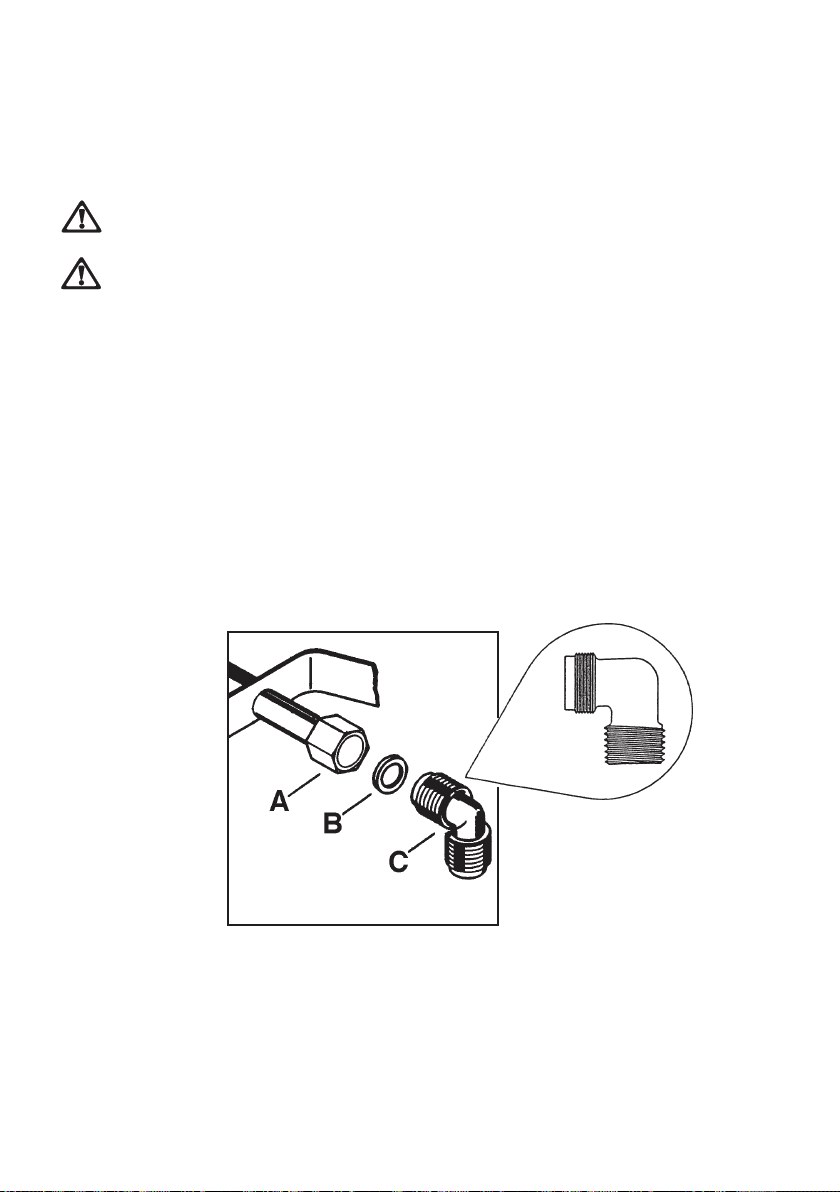
On the end of the shaft, which includes the G 1/2" threaded elbow,
adjustment is fixed so that the washer is fitted between the components
as shown in the diagram. Screw the parts together without using excessive
force.
TT
ANTANT
T
ANT
TT
ANTANT
This hob must be installed by a competent person to theThis hob must be installed by a competent person to the
This hob must be installed by a competent person to the
This hob must be installed by a competent person to theThis hob must be installed by a competent person to the
relevant Gas Standards.relevant Gas Standards.
relevant Gas Standards.
relevant Gas Standards.relevant Gas Standards.
Any gas installation must be carried out by a registeredAny gas installation must be carried out by a registered
Any gas installation must be carried out by a registered
Any gas installation must be carried out by a registeredAny gas installation must be carried out by a registered
competent person.competent person.
competent person.
competent person.competent person.
A) End of shaft with nut
B) Washer
C) Elbow
Page 18
18 electrolux
Gas ConnectionGas Connection
Gas Connection
Gas ConnectionGas Connection
Connection to the gas supply should be with either rigid or semi-rigid pipe, i.e. steel
or copper.
The connection should be suitable for connecting to R 1/2 (1/2 BSP male thread).
When the final connection has been made, it is essential that a thorough leak test is
carried out on the hob and installation.
Ensure that the main connection pipe does not exert any strain on the hob.
It is important to install the elbow corrIt is important to install the elbow corr
It is important to install the elbow corr
It is important to install the elbow corrIt is important to install the elbow corr
the end of the thread, fitted to the hob connecting pipe.the end of the thread, fitted to the hob connecting pipe.
the end of the thread, fitted to the hob connecting pipe.
the end of the thread, fitted to the hob connecting pipe.the end of the thread, fitted to the hob connecting pipe.
Failure to ensure the correct assembly will cause leakage of gas.Failure to ensure the correct assembly will cause leakage of gas.
Failure to ensure the correct assembly will cause leakage of gas.
Failure to ensure the correct assembly will cause leakage of gas.Failure to ensure the correct assembly will cause leakage of gas.
LocationLocation
Location
LocationLocation
ectlyectly
, with the shoulder on, with the shoulder on
ectly
, with the shoulder on
ectlyectly
, with the shoulder on, with the shoulder on
The hob may be located in a kitchen, a
kitchen/diner or bed sitting room, but not
in a bathroom, shower room or garage.
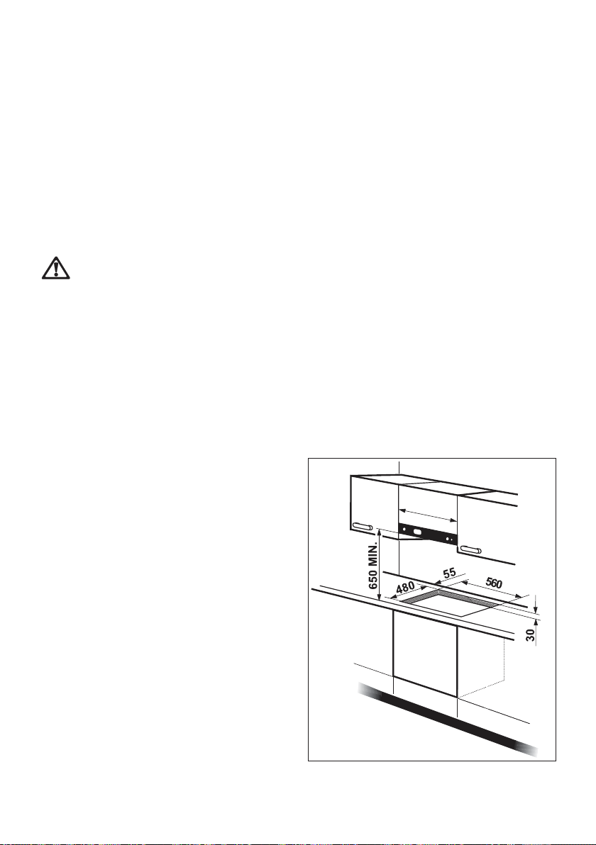
Ensure that there is a minimum distance
of 55 mm between the rear cut out edge
and the wall.
A minimum distance of 100 mm must be
left between the side edges of the cut out
6
0
0
M
IN
.
and any adjacent cabinets or walls.
The minimum distance combustible
material can be fitted above the hob in
line with the edges of the hob is 400 mm.
If it is fitted below 400 mm a space of 50
mm must be allowed from the edges of
the hob.
The minimum distance combustible
material or a cooker hood can be fitted
above the hob is 650 mm.
For appliances installed in the Republic
of Ireland please refer to NSAI- Domestic
Gas Installation I.S 813 Current Edition
Section 7- Permitted Locations of
Appliance.
Page 19
Fitting the Hob into the
Worktop
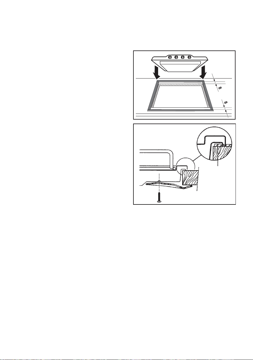
Carry out the building in of the hob as
follows:
1. place the seals supplied with
the hob on the side edges of the
cut out and at 8 mm. from the
front and rear edges, as shown
in the diagram, taking care that
the seals meet without
overlapping;
2. place the hob in the cut out,
taking care that it is centred;
3. fix the hob with the relevant
fixing clamps and screws, as
shown in the diagram. When the
screws have been tightened,
the excess seal can be
removed.
electrolux 19
Seal
The edge of the hob forms a double seal
which prevents the ingress of liquids.
Page 20
20 electrolux
Building InBuilding In
Building In
Building InBuilding In
BB
uilding over a cupboard or draweruilding over a cupboard or drawer
B
uilding over a cupboard or drawer
BB
uilding over a cupboard or draweruilding over a cupboard or drawer
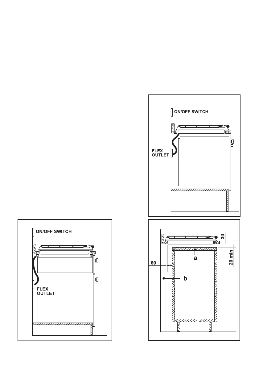
If the hob is to be installed above a cupboard or drawer it will be necessary to fit a
heat resistant board below the base of the hob on the underside of the work surface.
It is also recommended to carry out the electrical connection to the hob as shown
in diagrams 1 and 2.
BB
uilding over a kitchen unit withuilding over a kitchen unit with
B
uilding over a kitchen unit with
BB
uilding over a kitchen unit withuilding over a kitchen unit with
doordoor
door
doordoor
Proper arrangements must be taken in designing
the furniture unit, in order to avoid any contact
with the bottom of the hob which can be heated
when it is operated. The recommended solution
is shown in diagram 3.
The panel fitted under the hob ("a") should be
easily removable to allow easy access if
technical assistance is needed. The space
behind the kitchen unit ("b") can be used for
connections.
Dimensions are given in mm.
2
1
3
Page 21
electrolux 21
Electrical ConnectionsElectrical Connections
Electrical Connections
Electrical ConnectionsElectrical Connections
Any electrical work required to install this hob should beAny electrical work required to install this hob should be
Any electrical work required to install this hob should be
Any electrical work required to install this hob should beAny electrical work required to install this hob should be
carried out by a qualified electrician or competent person,carried out by a qualified electrician or competent person,
carried out by a qualified electrician or competent person,
carried out by a qualified electrician or competent person,carried out by a qualified electrician or competent person,
in accordance with the current regulations.in accordance with the current regulations.
in accordance with the current regulations.
in accordance with the current regulations.in accordance with the current regulations.
THIS HOB MUST BE EARTHED.THIS HOB MUST BE EARTHED.
THIS HOB MUST BE EARTHED.
THIS HOB MUST BE EARTHED.THIS HOB MUST BE EARTHED.
Electrical RequirementsElectrical Requirements
Electrical Requirements
Electrical RequirementsElectrical Requirements
Any permanent electrical installation must comply with the latest I.E.E.
Regulations and local Electricity Board regulations. For your own safety
this should be undertaken by a qualified electrician, e.g. your local Electricity
Board, or a contractor who is on the roll of the National Inspection Council
for Electrical Installation Contracting (NICEIC).
The manufacturer declines any liability should these safety
measures not be observed.
This hob is designed to be connected to a 230 V 50 Hz AC electrical supply.
Before switching on, make sure the electricity supply voltage is the same
as that indicated on the hob rating plate. The rating plate is located on the
bottom of the hob. A copy is attached on
the back cover of this book.
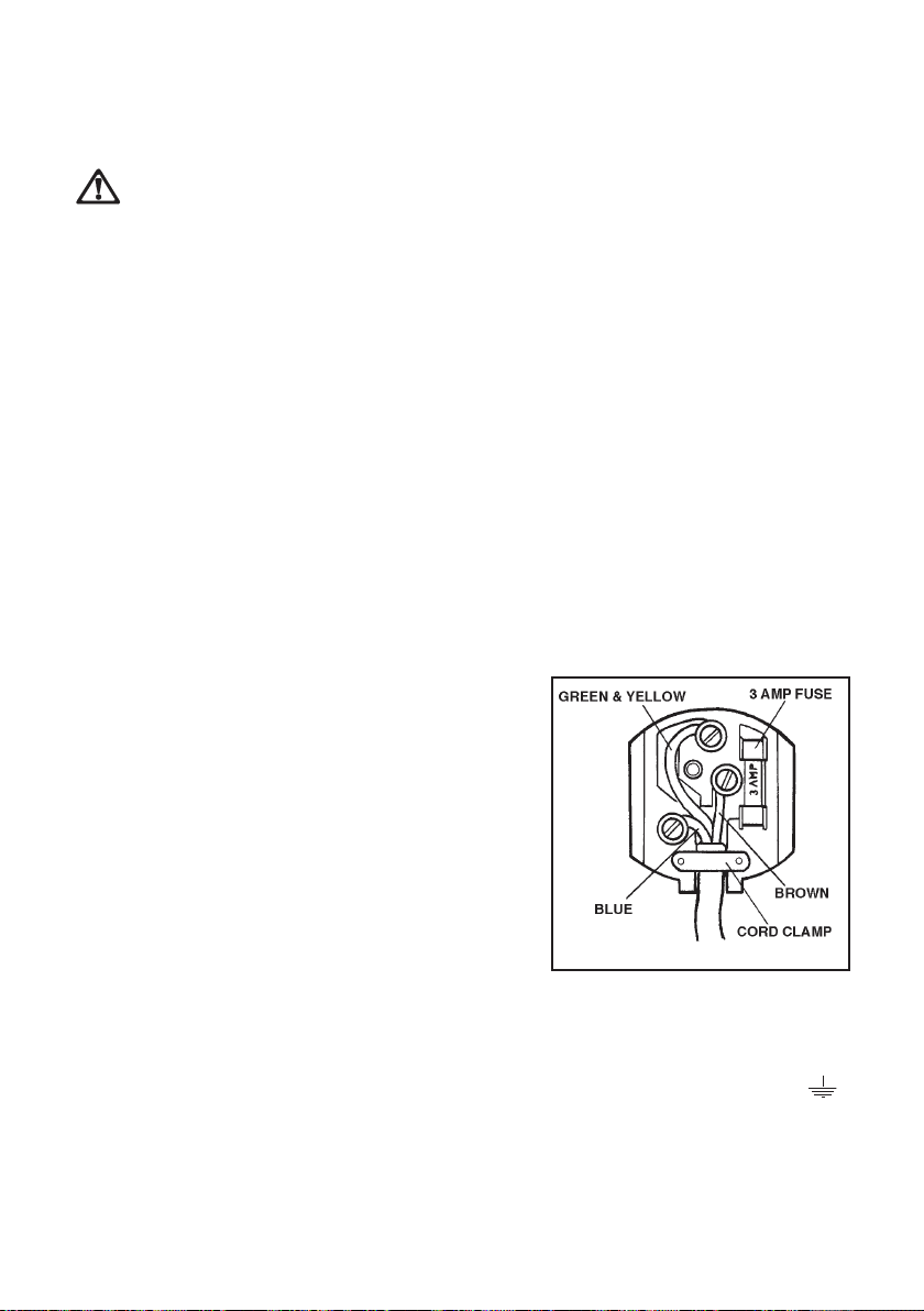
The hob is supplied with a 3 core flexible
supply cord incorporating a 3 amp plug
fitted. In the event of having to change the
fuse, a 3 amp ASTA approved (BS 1362)
fuse must be used.
Should the plug need to be replaced for
any reason, the wires in the mains lead are
coloured in accordance with the following
code:
Green and Yellow - Earth
Blue - Neutral
Brown - Live
1) Connect the green and yellow (earth) wire to the terminal in the
!!
!
!!
plug which is marked with the letter 'E' or the earth symbol
or coloured green and yellow.
2) Connect the blue (neutral) wire to the terminal in the plug which
is marked with the letter 'N' or coloured black.
3) Connect the brown (live) wire to the terminal in the plug which
is marked with the letter 'L' or coloured red.
FO 0390
Page 22
22 electrolux
Upon completion there must be no cut, or stray strands of wire present
and the cord clamp must be secure over the outer sheath.
A cut off plug inserted into a 13 amp socket is a seriousA cut off plug inserted into a 13 amp socket is a serious
A cut off plug inserted into a 13 amp socket is a serious
A cut off plug inserted into a 13 amp socket is a seriousA cut off plug inserted into a 13 amp socket is a serious
safety (shock) hazard. Ensure that the cut off plug is disposedsafety (shock) hazard. Ensure that the cut off plug is disposed
safety (shock) hazard. Ensure that the cut off plug is disposed
safety (shock) hazard. Ensure that the cut off plug is disposedsafety (shock) hazard. Ensure that the cut off plug is disposed
of safelyof safely
of safely
of safelyof safely
The replacement of electric cable must be carried out ex-The replacement of electric cable must be carried out ex-
The replacement of electric cable must be carried out ex-
The replacement of electric cable must be carried out ex-The replacement of electric cable must be carried out exclusively by the service force centre or by personnel withclusively by the service force centre or by personnel with
clusively by the service force centre or by personnel with
clusively by the service force centre or by personnel withclusively by the service force centre or by personnel with
similar competencies, in accordance with the current regu-similar competencies, in accordance with the current regu-
similar competencies, in accordance with the current regu-
similar competencies, in accordance with the current regu-similar competencies, in accordance with the current regulations.lations.
lations.
lations.lations.
Permanent ConnectionPermanent Connection
Permanent Connection
Permanent ConnectionPermanent Connection
In the case of a permanent connection, it is necessary that you install a
double pole switch between the hob and the electricity supply (mains),
with a minimum gap of 3 mm between the switch contacts and of a type
suitable for the required load in compliance with the current electric
regulations.
The switch must not break the yellow and green earth cable at any point.
..
.
..
Ensure that the hob supply cord does not come into contactEnsure that the hob supply cord does not come into contact
Ensure that the hob supply cord does not come into contact
Ensure that the hob supply cord does not come into contactEnsure that the hob supply cord does not come into contact
with surfaces with temperatures higher than 50 deg. C.with surfaces with temperatures higher than 50 deg. C.
with surfaces with temperatures higher than 50 deg. C.
with surfaces with temperatures higher than 50 deg. C.with surfaces with temperatures higher than 50 deg. C.
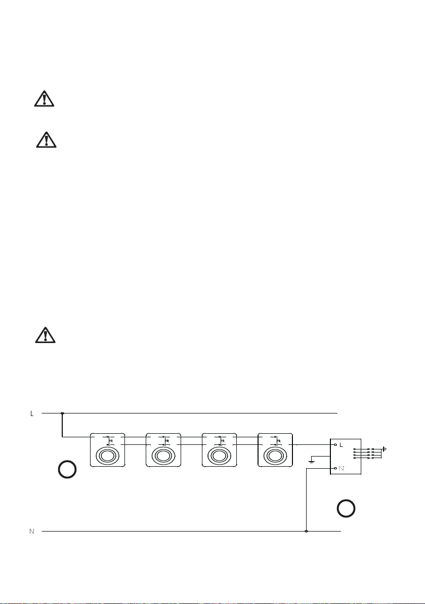
Wiring diagramWiring diagram
Wiring diagram
Wiring diagramWiring diagram
11
1
11
1. TAPS IGNITOR SWITCHES
2. IGNITOR UNIT
22
2
22
Page 23
Fault FindingFault Finding
Fault Finding
Fault FindingFault Finding
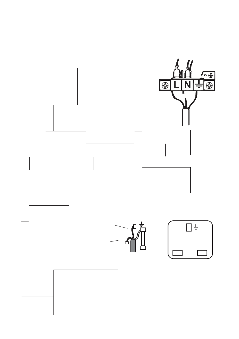
Preliminary Electrical Systems CheckPreliminary Electrical Systems Check
Preliminary Electrical Systems Check
Preliminary Electrical Systems CheckPreliminary Electrical Systems Check
STARTSTART
START
STARTSTART
Isolate appliance
and carry out:
A:A:
A: Earth Continuity
A:A:
check.
YESYES
NONO
NO
NONO
Has inlet fuse blown?
YES
YESYES
Carry out:
C:C:
C: Polarity check.
C:C:
Brown
Brown
Carry out:
D:D:
D: Resistance to
D:D:
Earth check.
electrolux 23
Blue
Blue
Green
Yellow
NONO
NO
NONO
Inlet wiring
faulty.
Rectify any
fault.
YESYES
YES
YESYES
PLUG (with cover removed)PLUG (with cover removed)
PLUG (with cover removed)
PLUG (with cover removed)PLUG (with cover removed)
Earth Wire
Green/Yellow
Neutral Wire
Blue
Isolate appliance and
carry out:
B:B:
B: Insulation check.
B:B:
Rectify any fault
including replacing
fuses as necessary.
Electricity supply
should now be
satisfactory.
( )
FUSE
SOCKETSOCKET
SOCKET
SOCKETSOCKET
(face view)(face view)
(face view)
(face view)(face view)
( )
E
N
L
Page 24

24 electrolux
A. EARTH CONTINUITY CHECKA. EARTH CONTINUITY CHECK
A. EARTH CONTINUITY CHECK
A. EARTH CONTINUITY CHECKA. EARTH CONTINUITY CHECK
Appliance must be electrically disconnected - meter set on W (Ohms)
x 1 scale and adjust zero if necessary.
— Test leads from any appliance earth point to earth pin on plug.
Resistance should be less than 0.1 W (Ohm), check all earth wires
for continuity and all contacts clean and tight.
B. INSULAB. INSULA
B. INSULA
B. INSULAB. INSULA
TION CHECKTION CHECK
TION CHECK
TION CHECKTION CHECK
Appliance electrically disconnected, all switches ON.
a) meter set on W (Ohms) x 1 scale.
Test leads from L to N in appliance terminal block. If meter reads
«0» then there is a short circuit.
b) meter set on W (Ohm) x 100 scale.
Repeat test with leads from L to E. If meter reads less than ×
(infinity) there is a fault.
NOTE - Should it be found that the fuse has failed but no fault is indicated
- a detailed continuity check (i.e. by disconnecting and checking each
component) is required to trace the faulty component.
It is possible that a fault could occur as a result of local burning/arcing but
no fault could be found under test. However a detailed visual inspection
should reveal evidence of burning around the fault.
Page 25
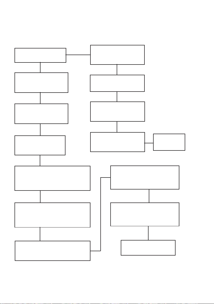
Ignition System / Gas IgnitionIgnition System / Gas Ignition
Ignition System / Gas Ignition
Ignition System / Gas IgnitionIgnition System / Gas Ignition
YESYES
YES
Ignitor does not spark
NONO
NO
NONO
YESYES
Check gas supply at
burner
electrolux 25
Check plug top fuse and
replace if necessary
Check polarity and
earth continuity of
supply point
Check earth continuity
of appliance
Check continuity from 'N' on the
mains connector block and "O" on
the ignitor unit
Check continuity from 'L' on the
mains connector block and the
taps ignition switches
Light burner manually
Check by pass simmer
adjusted
Check position of the
electrode
Check continuity from the tip of
each electrode to the terminals
1 to 4 on the ignitor unit
Check for breaks in the
insulation of the HT leads
Check fitting
of burners
Check continuity from ignition
switches connector to ignitor unit
Change the ignitor unit
Page 26
26 electrolux
CommissioningCommissioning
Commissioning
CommissioningCommissioning
When the hob has been fully installed it will be necessary to check the
minimum flame setting. To do this, follow the procedure below.
1) Turn the gas tap to the MAX position and ignite.
!!
!
!!
2) Set the gas tap to the MIN flame position then turn the control
knob from MIN to MAX several times. If the flame is unstable or is
extinguished follow the procedure below.
Procedure:Procedure:
Procedure:
Procedure:Procedure:
1) Re-ignite the burner and set
!!
!
!!
to MIN.
2) Remove the control knob.
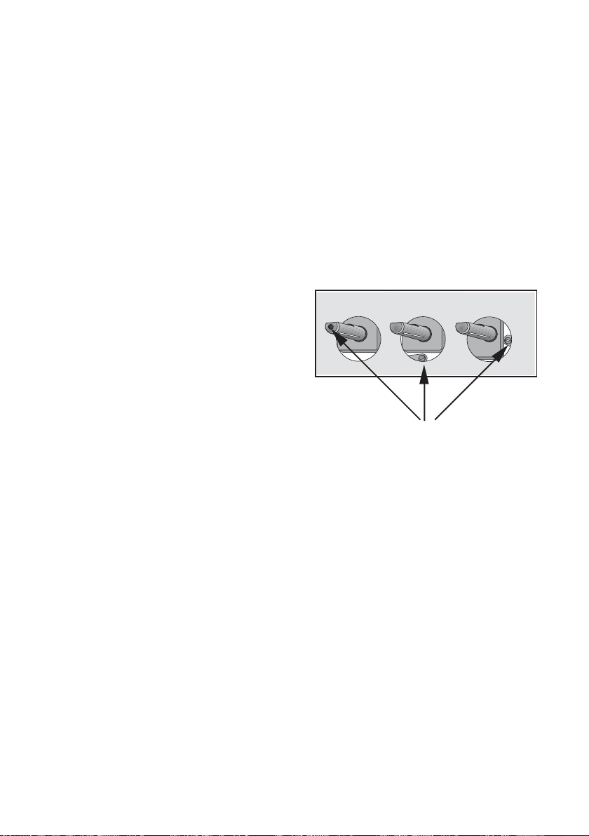
3) To adjust, use a thin bladed
screwdriver and turn the
adjustment screw (see
diagram) until the flame is
steady and does not
extinguish, when the knob is
turned from MIN to MAX.
Repeat this procedure for all
burners.
Minimum adjustmentMinimum adjustment
Minimum adjustment
Minimum adjustmentMinimum adjustment
screwscrew
screw
screwscrew
PrPr
essuressur
Pr
essur
PrPr
essuressur
The pressure testing must be carried out on the burners.
!!
!
!!
e Te T
estingesting
e T
esting
e Te T
estingesting
Proceed as follows:
1) Remove the pan supports and the burner caps and crowns.
2) Fit manometer tube over the injector.
3) Turn on the burner gas supply and ignite another burner supply.
The pressure reading should be nominally 20 mbar and must be
between 17 mbar and 25 mbar.
4) Turn off the burner supplies.
Page 27

Conversion from Natural Gas to LPGConversion from Natural Gas to LPG
Conversion from Natural Gas to LPG
Conversion from Natural Gas to LPGConversion from Natural Gas to LPG
electrolux 27
IMPORIMPOR
IMPOR
IMPORIMPOR
The replacement/conversion from natural gas to LPG should onlyThe replacement/conversion from natural gas to LPG should only
The replacement/conversion from natural gas to LPG should only
The replacement/conversion from natural gas to LPG should onlyThe replacement/conversion from natural gas to LPG should only
be undertaken by a competent person.be undertaken by a competent person.
be undertaken by a competent person.
be undertaken by a competent person.be undertaken by a competent person.
It is important to note that this model is designed for use with natural gas but can be
converted for use with butane or propane gas providing the correct injectors are
fitted. The gas rate is adjusted to suit.
MethodMethod
Method
MethodMethod
1) Ensure that the gas taps are in the 'OFF' position
!!
!
!!
2) Isolate the hob from the electricity supply
3) Remove all pan supports, burner caps, rings, crowns and control knobs.
4) With the aid of a 7mm box spanner the burner injectors can then be
TO ADJUST THE GAS RATO ADJUST THE GAS RA
TO ADJUST THE GAS RA
TO ADJUST THE GAS RATO ADJUST THE GAS RA
With the aid of a thin bladed screwdriver completely tighten down the by
pass adjustment screw. Upon completion stick the replacement rating plate
on the under side of the hob.
TT
ANTANT
T
ANT
TT
ANTANT
unscrewed and replaced by the appropriate LPG injectors.
TETE
TE
TETE
Page 28

28 electrolux
Standard Guarantee Conditions
We, Electrolux, undertake that if within 12 months of the date of the purchase this
Electrolux appliance or any part thereof is proved to be defective by reason only of
faulty workmanship or materials, we will, at our option repair or replace the same
FREE OF CHARGE for labour, materials or carriage on condition that:
•The appliance has been correctly installed and used only on the gas and electricity
supply stated on the rating plate.
•The appliance has been used for normal domestic purposes only, and in accordance
with the manufacturer’s instructions.
•The appliance has not been serviced, maintained, repaired, taken apart or tampered
with by any person not authorised by us.
•Electrolux Service Force Centre must undertake all service work under this
guarantee.
•Any appliance or defective part replaced shall become the Company’s property.
•This guarantee is in addition to your statutory and other legal rights.
Exclusions
•Damage or calls resulting from trans-portation, improper use or neglect, the
replacement of any light bulbs or removable parts of glass or plastic.
•Costs incurred for calls to put right an appliance which is improperly installed or
calls to appliances outside the United Kingdom.
•Appliances found to be in use within a commercial environment, plus those which
are subject to rental agreements.
•Products of Electrolux manufacturer that are not marketed by Electrolux.
Page 29

electrolux 29
Service and Spare Parts
In the event of your appliance requiring service, or if you wish to purchase spare parts,
please contact your local Service Force Centre by telephoning
0870 5 929 929
Your telephone call will be automatically routed to the Service Force Centre co-vering
your postcode area.
For the address of your local Service Force Centre and further information about Service
Force, please visit the website at
www.serviceforce.co.uk
Before calling out an engineer, please ensure you have read the details under the
heading “Something not working”. When you contact the Service Force Centre you
will need to give the follo-wing details:
1.Your name, address and postcode.
2.Your telephone number.
3. Clear concise details of the fault.
4. The model and Serial number of the appliance (found on the rating plate).
5.The purchase date.
Please note a valid purchase receipt or guarantee documentation is required for in
guarantee service calls.
Customer CareCustomer Care
Customer Care
Customer CareCustomer Care
For general enquiries concerning your Electrolux appliance, or for further information
on Electrolux products please contact our Customer Care Department by letter or
wwwwww
.electr.electr
telephone at the address below or visit our website at
Customer Care Department
Electrolux Major Appliances
Addington Way
Luton
Bedfordshire, LU4 9QQ
Tel: 08705 950 950 (*)
(*) Calls may be recorded for training purposes
www
wwwwww
.electr
.electr.electr
olux.co.ukolux.co.uk
olux.co.uk
olux.co.ukolux.co.uk
Page 30

30 electrolux
European GuaranteeEuropean Guarantee
European Guarantee
European GuaranteeEuropean Guarantee
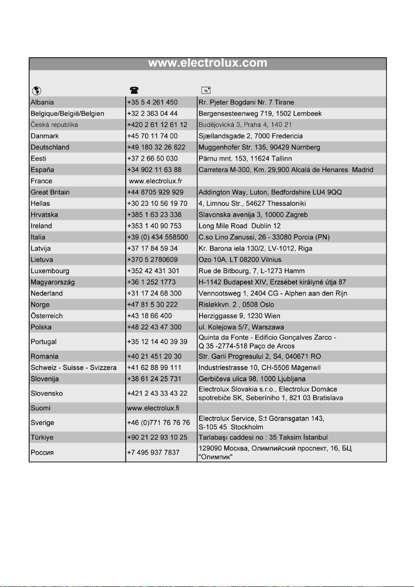
This appliance is guaranteed by Electrolux in each of the countries listed
at the back of this user manual, for the period specified in the appliance
guarantee or otherwise by law. If you move from one of these countries to
another of the countries listed below the appliance guarantee will move
with you subject to the following qualifications:
• The appliance guarantee starts from the date you first purchased the
appliance which will be evidenced by production of a valid purchase
document issued by the seller of the appliance.
• The appliance guarantee is for the same period and to the same extent
for labour and parts as exists in your new country of residence for this
particular model or range of appliances.
• The appliance guarantee is personal to the original purchaser of the
appliance and cannot be transferred to another user.
• The appliance is installed and used in accordance with instructions
issued by Electrolux and is only used within the home, i.e. is not used
for commercial purposes.
• The appliance is installed in accordance with all relevant regulations in
force within your new country of residence.
The provisions of this European Guarantee do not affect any of the rights
granted to you by law.
Page 31
electrolux 31
Page 32

www.electrolux.co.uk
35687-8402 09/07 R.0
 Loading...