

Page 1
Electric Hob
INSTRUCTION BOOKLET
35670-2901
2
Models EHE 688 B - EHE 688 W
GB
Page 2

Important Safety Information
Installation
You MUST read these warnings carefully before installing or using the hob.
If you need assistance, contact our Customer Care Department
on 01635 522799
● This hob must be installed by qualified personnel,
according to the manufacturer’s instructions and
to the relevant British Standards.
● Remove all packaging before using the hob.
● Ensure that the electrical supply complies with the
type stated on the rating plate, located on the
bottom of the hob.
● Do not attempt to modify the hob in any way.
Child Safety
● This hob is designed to be operated by adults. Do
not allow children to play near or with the hob.
● The hob gets hot when it is in use. Children should
be kept away until it has cooled.
● Children can also injure themselves by pulling
pans or pots off the hob.
● Never use plastic or aluminium foil dishes on the
hob.
● Perishable food, plastic items and areosols may be
affected by heat and should not be stored above or
below the hob unit.
Service
● This hob should only be repaired or serviced by an
authorised Service Engineer and only genuine
approved spare parts should be used.
Environmental Information
● After installation, please dispose of the packaging
with due regard to safety and the environment.
● When disposing of an old appliance, make it
unusable, by cutting off the cable.
During Use
● This hob is intended for domestic cooking only. It
is not designed for commercial or industrial
purposes.
● Do not use this hob if it is in contact with water.
Do not operate the hob with wet hands.
● Ensure the control knobs are in the ‘OFF’ position
when not in use.
● When using other electrical appliances, ensure the
cable does not come into contact with the hot
surfaces of the hob.
● Unstable or misshapen pans should not be used on
the hob as unstable pans can cause an accident by
tipping or spillage.
● Never leave the hob unattended when cooking
with oil and fats.
Keep this instruction book for future
reference and ensure it is passed on
to any new owner.
3
Page 3

Contents
For the User
Description
of the Hob Page 5
Operation Page 6
Maintenance
and Cleaning Page 8
Something Not
Working? Page 9
Service and
Spare Parts Page 9
Guarantee Conditions Page 10
Electrolux Service Force
Centre Address Page 11
For the Installer
Technical Data Page 13
Important Safety
Requirements Page 13
Installation Page 15
Building In Page 15
Electrical Connection Page 16
Wiring Diagram Page 17
Guide to Use the instructions
The following symbols will be found in the text to
guide you throughout the Instructions:
Safety Instructions
☞
i
Step by step instructions for an
operation
Hints and Tips
This appliance is manufactured according
to the following EEC directives:
73/23 EEC - 90/683 EEC - 93/68 EEC 89/336 EEC current edition.
4
Page 4
Description of the Hob
1
6
7
2
8
9
3
5
4
10
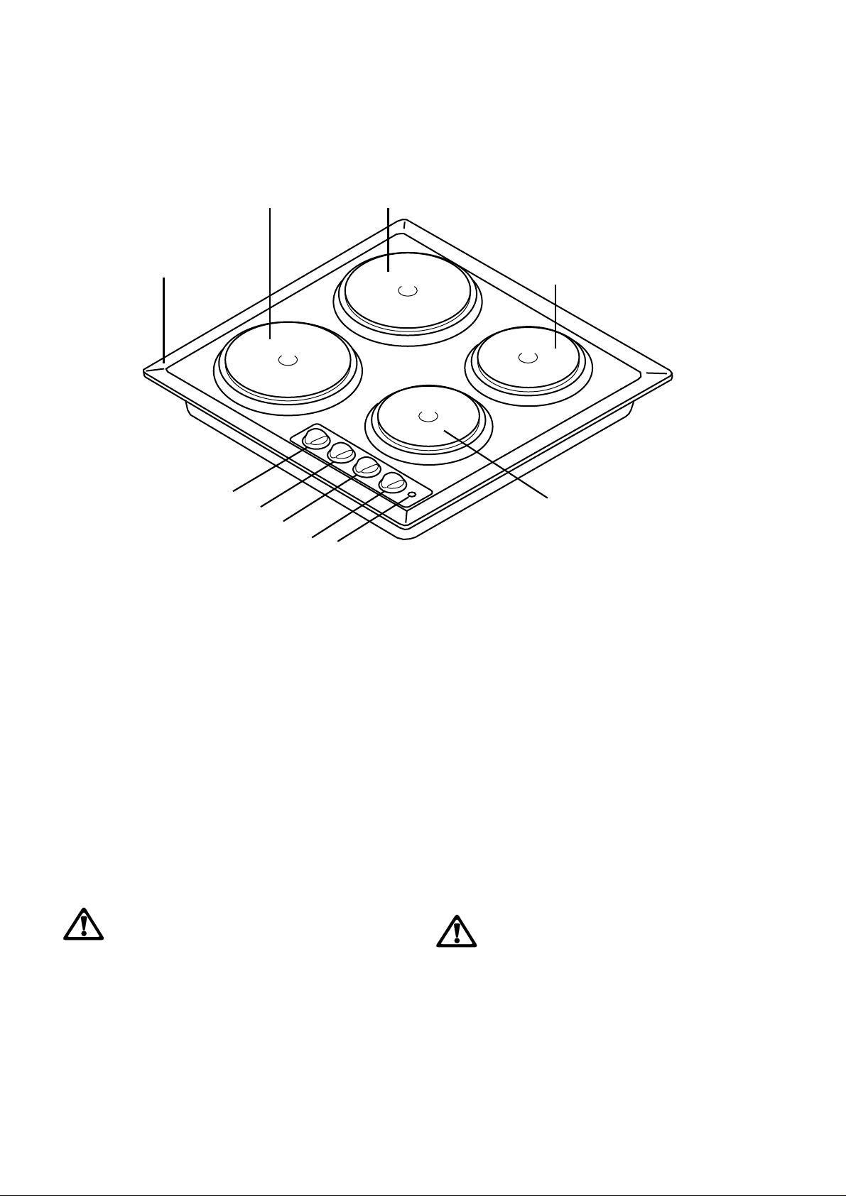
1. Hob Top
2. Rapid Hotplate - 2090 W/180 mm dia.
3. Normal Hotplate - 1570 W/180 mm dia.
4. Rapid Hotplate - 1570 W/145 mm dia.
5. Normal Hotplate - 1040 W/145 mm dia.
6. Control knob for back left hotplate
7. Control knob for front left hotplate
8. Control knob for front right hotplate
9. Control knob for back right hotplate
10.Electric Hotplates Control Light
INSTALLATION
The hob must be installed according to the
instructions supplied.
The hob must be installed by qualified
personnel to the relevant British Standards.
Please, ensure that, once the hob is
installed, it is easily accessible for the
engineer in the event of a breakdown.
WHEN THE HOB IS FIRST INSTALLED
Once the hob has been installed, it is
important to remove any protective
materials, which were put on in the factory.
5
Page 5
Operation
ELECTRIC HOTPLATES
To switch on a hotplate, turn the relevant control
knob anticlockwise to the required heat setting.
The control knob is numbered 1 - 6
0 - OFF
1 - Minimum
2 - Maximum.
The hob has two types of hotplates:
Normal Hotplates
We recommend the plates are switched to maximum
(6) for a short while to boost the plate, and then
adjusted to the required setting.
Rapid Hotplates
The rapid hotplates are indicated by a red dot, and
will heat up more quickly than a normal plate. As the
red dots are painted on the plate, they may deteriorate
during use and even disappear completely after a
period of time. This will not affect the performance
of the hob.
It is important to note that the plate may smoke
i
a little and produce a slightly unpleasant odour
when used for the first time. This is quite
normal and will disappear after a few minutes.
Suggestions for the correct setting of the plates are
given in the following table.
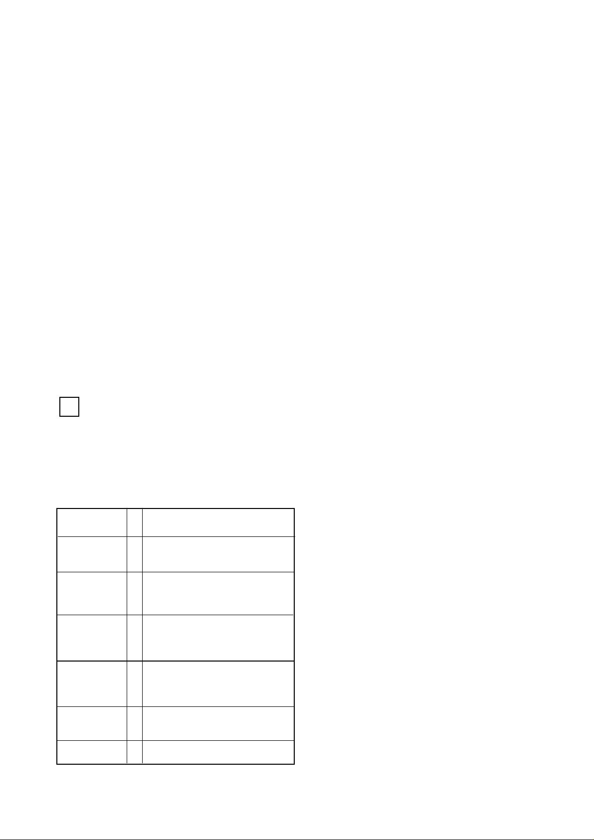
OFF 0
Very Gentle 1 To keep food warm
To melt butter and chocolate
Gentle 2 To prepare cream-sauces,
stews and milk puddings
or to fry eggs
Slow 3 Dried vegetables, frozen
food, fruit, boling water
or milk
Medium 4 Boiled potatoes, fresh
vegetables, pâtés, soups,
broths, pancakes or fish
High 5 Larger stews, meat roll, fish,
omelettes, steaks
Fast 6 Steaks, escalopes and frying.
6
Page 6
Hints and Tips
i
Saucepans for use on solid plates should have several
characteristics:
● They should be fairly heavy duty
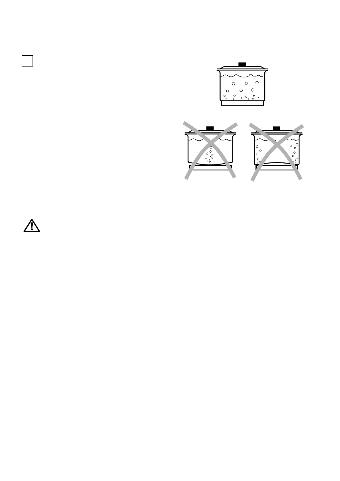
● They should fit the heat area exactly, or be slightly
larger for efficient use, NEVER smaller.
● They should have a flat base to ensure good
contact with the plate.
This is particularly important when using pans for
high temperature frying or pressure cooking.
As soon as liquid starts boiling, turn down the plate
control knob so that it will barely keep the liquid
simmering.
You can switch off the plate a short while before you
finish cooking, and the final stage will be completed
on the accumulated heat. Similarly, stews etc. cooked
in well covered saucepans cook at lower temperature
which is more economical.
Ensure pans are large enough to avoid
liquids being split onto the plates.
Never leave the plates on without a pan on
them or with an empty pan on them.
Take care never to lean or reach over a hot
electric plate. Always point pan handles
inward or over the work surface next to the
hob to avoid accidentally knocking over a
pan as you pass by.
Take care when frying food in hot oil or fat,
as the overheated splashes could easily
ignite.
If the control knobs become difficult to turn,
please contact your local Electrolux Service
Centre.
7
Page 7
Maintenance and Cleaning
Before any maintenance or cleaning can be
carried out, you must DISCONNECT the
hob from the electricity supply.
The hob is best cleaned whilst it is still warm, as
spillage can be removed more easily than if it is left
to cool.
The Hob Top
Regularly wipe over the hob top using a soft cloth
well wrung out in warm water to which a little
wasing up liquid has been added. Avoid the use of the
following:
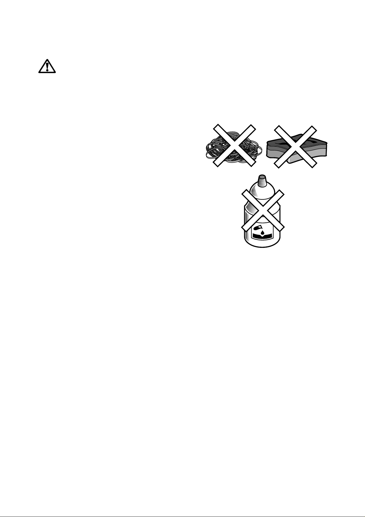
- household detergent and bleaches;
- impregnated pads unsuitable for non-stick saucepans;
- steel wool pads;
- bath/sink stain removers.
Should the hob top become heavily soiled, it is
recommended that a cleaning product such as Hob
Brite or Bar Keepers Friend is used.
The control knobs may be removed by carefully
pulling them upward for easier cleaning.
The Hotplates
Spills onto the actual plate should be removed using
warm water and a soft brush, nylon or plastic scourer.
To keep the plates looking as new, hotplate
conditioner can be purchased from most hardware
stores, e.g. "4 Hob" by HomeCare Products (follow
the manufacturer's instruction for use).
Alternatively, wipe the plates with a drop of olive oil
on a kitchen towel to avoid rust. It is important to
note that the plate will smoke a little and produce a
slightly unpleasant odour when next used.
8
Page 8
Something Not Working?
If the hob is not working correctly, please carry out the following checks before contacting your local
Electrolux Service Force Centre.
SYMPTOM
■ The plate does not heat up.
■ The plate is not giving satisfactory results
If after all these checks, your hob still does not
operate correctly, contact your local Electrolux
Service Force Centre.
Please note that it will be necessary to provide proof
of purchase for any in-guarantee service calls.
SOLUTION
◆ Check that the unit is plugged in and the electrical
supply is switched on
◆ Check that the RCCB has not tripped (if fitted)
◆ Check the mains fuse has not blown
◆ Check the correct control knob has been turned.
◆ Check the plate is clean and dry
◆ Check the cooking pan is the correct size for the plate.
◆ Check the cooking pan has a flat bottom
◆ Check the setting is correct for the type of cooking.
In-guarantee customers should ensure that the
above checks have been made as the engineer will
make a charge if the fault is not a mechanical or
electrical breakdown.
Service and Spare Parts
If you require spare parts or an engineer contact your
local Service Force Centre by telephoning:
0990-929929
Your call will be routed to the Service Centre
covering your post code area. The addresses of
Electrolux Service Force Centres are detailed on the
following pages.
When you contact the Service Centre, they will need
the following information:
1. Your name, address and post code.
2. Your telephone number
3. Clear and concise details of the fault
4. The model and the serial number (see rating label
on the back of this instruction booklet)
5. Date of purchase
CUSTOMER CARE
For general enquiries concerning your Electrolux
appliance and for further information on Electrolux
products, contact our Customer Care Department by
letter or telephone as follows:
Customer Care Department
Electrolux
PO Box 47
Newbury
RG14 5XL
Tel : 01635 52 27 99
9
Page 9

Guarantee Conditions
ELECTROLUX STANDARD GUARANTEE
CONDITIONS
We, Electrolux, undertake that if, within 12 months
of the date of the purchase, this Electrolux appliance
or any part thereof is proved to be defective by any
reason only of faulty workmanship or materials, we
will, at our option, repair or replace the same FREE
OF ANY CHARGE for labour, materials or carriage
on condition that:
* The appliance has been correctly installed and
used only on the gas and electricity supply stated
on the rating plate.
* The appliance has been used for normal domestic
purposes only, and in accordance with the
manufacturer's instructions.
* The appliance has not been serviced, maintained,
repaired, taken apart or tampered with by any
person not authorised by us.
* All service work under this guarantee must be
undertaken by a Electrolux Service Force Centre.
* Appliances found to be in use within a
commercial or similar environment, plus those
which are the subject to rental agreements.
* Products of Electrolux manufacture which are not
marketed by Electrolux.
European Guarantee
If you should move to another country within Europe
then your guarantee moves with you to your new
home subject to the following qualifications:
* The guarantee starts from the date you first
purchased your product.
* The guarantee is for the same period and to the
same extent for labour and parts as exist in the
new contry of use for this brand or range of
products.
* This guarantee relates to you and cannot be
transferred to another user.
* Your new home is within the European
Community (EC) or European Free Trade Area.
* Any appliance or defective part replaced shall
become the Company's property.
* This guarantee is in addition to your statutory and
other legal rights.
Home visits are made between 8.30am and 5.30pm
Monday to Friday. Visits may be available outside
these hours, in which case a premium will be
charged.
Exclusions
This guarantee does not cover:
* Damage or calls resulting from transportation,
improper use or neglect, the replacement of any
light bulbs or removable parts of glass or plastic.
* Costs incurred for calls to put right an appliance
which is improperly installed or calls to appliance
outside the United Kingdom.
* The product is installed and used in accordance
with our instructions and is only used
domestically, i.e. a normal household
* The electrical supply complies with the
specification given in the rating label.
* The product is installed taking into account
regulations in your new country.
Before you move, please contact your nearest
Customer Care centre, listed below, to give them
details of your new home. They will then ensure that
the local Service Organisation is aware of your move
and able to look after you and your appliances.
France Senlis +33 (0)3 44 62 22 22
Germany Nürnberg +49 (0)911 323 2600
Italy Pordenone +39 (0)1678 47053
Sweden Stockholm +46 (0)20 78 77 50
UK Newbury +44 (0)1635 522 799
10
Page 10
ELECTROLUX SERVICE FORCE
To contact your local Electrolux Service Force Centre telephone 0990 929929
CHANNEL ISLANDS
GUERNSEY Guernsey Electricity
PO Box 4
Vale , Guernsey
Channel Islands
JERSEY Jersey Electricity
Company
PO Box 45
Queens Road
St Helier
Jersey
Channel Islands
JE4 8NY
SCOTLAND
ABERDEEN 8 Cornhill Arcade
(M05) Cornhill Drive
Aberdeen
AB2 5UT
AUCHTERMUCHY 33A Burnside
(M03) Auchtermuchy
Fife
KY14 7AJ
BLANTYRE Unit 5
(M07) Block 2
Auchenraith Industrial
Estate
Rosendale Way
Blantyre
G72 0NJ
DUMFRIES 93 Irish Street
(M01) Dumfries
Scotland
DG1 2PQ
DUNOON Briar Hill
7 Hill Street
(M 67) Dunoon
Argyll
PA23 7AL
GLASGOW 20 Cunningham Road
(M04) Clyde Estate
Rutherglen,
Glasgow,
G73 1PP
INVERNESS Unit 3B
(M06) Smithton Indust. Est.
Smithton
Inverness
IV1 2PD
ISLE OF ARRAN Arran Domestics
Unit 4 The Douglas
Centre
Brodick
Isle of Arran
(OWN SALES) KA27 8AJ
ISLE OF BARRA J Zerfah
244 Bruernish
Isle of Barra
Western Islands
(OWN SALES) HS9 5QY
ISLE OF BUTE Walker Engineering
(M66) Glenmhor
Upper Serpentine Road
Rothesay
Isle of Bute
PA20 9EH
ISLE OF LEWIS ND Macleod
(M69) 16 James Street
Stornoway
Isle of Lewis
P A872QW
KELSO 2-8 W ood Market
(M08) Kelso
Borders TD5 7AX
ORKNEY Corsie Domestics
(M65) 7 King Street
Kirkwall
Orkney KW15 1RE
SHETLAND Tait Electronic Systems
Ltd.
Holmsgarth Road
Lerwick
(OWN SALES) Shetland ZE1 0PW
SHETLAND Bolts Shetland Ltd
26 North Road
Lerwick
(OWN SALES) Shetland ZE1 0PE
WHALSAY Leask Electrical
Harlsdale
Symbister, Whalsay
(OWN SALES) Shetland ZE2 9AA
NORTHERN IRELAND
BELFAST Owenmore House
(M27) Kilwee Industrial Estate
Upper Dunmury Lane
Belfast
BT17 0HD
WALES
CARDIFF Guardian Industrial
(M28) Estate
Clydesmuir Road
Tremorfa, Cardiff
CF2 2QS
CLYWD Unit 6-7 Coed - Parc
(M14) Abergele Road
Rhuddlan
Clwyd
Wales
LL18 5UG
OSWESTRY Plas Funnon Warehouse
(M17) Middleton Road
Oswestry
SY11 2PP
HAVERFORDWEST Cromlech Lodge
(M75) Amerlston
Haverfordwest
SA62 5DS
NORTH EAST
GATESHEAD Unit 356a
(M39) Dukesway Court
Dukesway
Team Valley
Gateshead
NE11 0BH
GRIMSBY Unit 2
(M42) Cromwell Road
Grimsby
South Humberside
DN31 2BN
HULL Unit 1
(M41) Boulevard Industrial
Estate
Hull
HU3 4AY
LEEDS 64-66 Cross Gates Road
(M37) Leeds
LS15 7NN
NEWTON AYCLIFFE Unit 16
(M45) Gurney W ay
Aycliffe Ind Estate
Newton A ycliffe
DL5 6UJ
SHEFFIELD Pennine House
(M38) Roman Ridge Ind.
Roman Ridge Road
Sheffield
S9 1GB
NORTH WEST
BIRKENHEAD 1 Kelvin Park
(M11) Dock Road
Birkenhead
L41 1LT
CARLISLE Unit 8
(M10) South John Street
Carlisle
CA2 5AJ
ISLE OF MAN South Quay Ind Estate
(M64) Douglas
Isle of Man
LIVERPOOL Unit 1
(M15) Honeys Green Precinct
Honeys Green Lane
Liverpool
L12 9JH
MANCHESTER Unit 30
Oakhill Trading
(M09) Estate
Devonshire Road
Worsley
Manchester
M28 3PT
PRESTON Unit 250
(M13) Dawson Place
Walton Summit
Bamber Bridge
Preston
Lancashire
PR5 8AL
STOCKPORT Unit 20 Haigh Park
(M16) Haigh Avenue
Stockport
SK4 1QR
11
Page 11
ELECTROLUX SERVICE FORCE
To contact your local Electrolux Service Force Centre telephone 0990 929929
MIDLANDS
BIRMINGHAM 66 Birch Road East,
(M18) Wyrley Road Industrial
Estate
Witton
Birmingham
B67DB
BOURNE Manning Road Ind
(M44) Estate
Pinfold Road
Bourne
PE10 9HT
BRIDGNORTH 1 Underhill Street
(M72) Bridgnorth
Salop
WV16 4BB
GLOUCESTER 101 Rycroft Street
(M23) Gloucester
GL1 4NB
HEREFORD Unit 3
(M31) Bank Buildings
Cattle Market
Hereford
HE4 9HX
HIGHAM FERRERS The Old Barn
(M51) Westfield Terrace
Higham Ferrers
NN10 8BB
ILKESTON Unit 2
(M43) Furnace Road
Ilkeston
DE7 5EP
LEICESTER Unit 7
(M22) Oaks Industrial Estate
Coventry Road
Narborough
Leicestershire
LE0 5GF
LINCOLN Unit 8 Stonefield Park
(M40) Clifton Street
Lincoln
LN5 8AA
NEWCASTLE 18-21 Croft Road
UNDER LYME Brampton Industrial
(M12) Estate
Newcastle under Lyme
Staffordshire
ST5 0TW
NUNEATON 19 Ptarmigan Place
(M21) Townsend Drive
Nuneaton
CV11 6RX
REDDITCH Heming Road
(M20) Washford
Redditch
Worcestershire
B98 0DH
TAMWORTH Unit 3
(M19) Sterling Park
Claymore
Tamworth
B77 5DO
WORCESTER Unit 1
(M73) Northbrook Close
Gregorys Mill Ind Estate
Worcester
WR3 8BP
LONDON & EAST ANGLIA
CANVEY ISLAND 2-4 Sandhurst
CHELMSFORD Hanbury Road
(M47) Widford Ind Estate
COLINDALE Unit 14
(M53) Capital Park
ENFIELD 284 Alma Road
(M49) Enfield
GRAVESEND Unit B4,
(M57)
HARPENDEN Unit 4
(M46) Riverside Estate
LETCHWORTH 16-17 Woodsite Ind Est.
(M50) Works Road
LETCHWORTH 16-17 Woodsite Ind Est.
(M50) Works Road
LONDON 2/4 Royal Lane
(M76) Yiewsley
MOLESEY 10 Island Farm Avenue
(M61) West Molesey
NEWBURY PO BOX 5672
(M24) Newbury
IPSWICH Unit 2B
(M48) Elton Park Business
NORWICH 2b Trafalgar Street
(M52) Norwich
SUNBURY Unit 1a
(M63) The Summit
SYDENHAM Unit 6
(M62) Metro Centre
Kings Road
Canvey Island
SS8 0QY
Chelmsford
Essex
CM12 3AE
Capital W ay
Colindale
London NW9 0EQ
London
EN3 7BB
Imperial Business Estate
Gravesend
Kent
DA11 0DL
Coldharbour Lane
Harpenden
AL5 4UN
Letchworth
Herts
SG6 1LA
Letchworth
Herts
SG6 1LA
West Drayton
Middlesex
UB7 8DL
Surrey
KT8 2UZ
Berkshire
RG14 5GF
Centre
Hadleigh Road
Ipswich
IP2 0DD
NR1 3HN
Hanworth Road
Hanworth Ind Estate
Sunbury on Thames
TW16 5D
Kangley Bridge Road
Sydenham
SE26
SOUTH EAST
ASHFORD Unit 2
(M58) Bridge Road Business
FLEET Unit 1
(M59) Redfields Industrial
HAYWARDS HEATH 21-25 Bridge Road
(M55) Haywards Heath
TONBRIDGE Unit 30 Deacon Trading
(M56) Estate
Estate
Bridge Road
Ashford
Kent
TN2 1BB
Estate
Church Crookham
Fleet
Hampshire
GU13 0RD
Sussex
RH16 1UA
Morley Road
Tonbridge
Kent
TN9 1RA
SOUTH WEST
BARNSTAPLE P.O. Box 12
(M30) Barnstaple
BOURNEMOUTH 63-65 Curzon Road
(M26) Bournemouth
BRIDGEWATER
(M35) Bridgewater
BRISTOL 11 Eldon Way
(M25) Eldonwall Trading
EMSWORTH 266 Main Road
(M33) Southboure
ISLE OF WIGHT Unit 8
(M34) Enterprise Court
NEWTON ABBOT Unit 2
(M29)
PLYMOUTH 16 Faraday Mill
(M32) Cattledown
REDRUTH Unit 7D Pool Industrial
(M36) Estate
North Devon
EX31 2YB
Dorset
BH1 4PW
6 Hamp Industrial Estate
Somerset
Bristol
Avon
BS4 3QQ
Emsworth
PO10 8JL
Ryde Business Park
Ryde
Isle of Wight
PO33 1DB
Zealley Industrial Estate
Kingsteignton
Newton Abbot
S. Devon
TQ12 3TD
Plymouth
PL4 0ST
Wilson W ay, Redruth,
Cornwall
TR15 3QW
12
Page 12
Instructions for the Installer
Engineer technical data
OVERALL DIMENSIONS
Width: 580 mm.
Depth: 510 mm.
Height: 88 mm.
Weight: 11 Kg.
CUT OUT DIMENSIONS
Width: 560 mm.
Depth: 480 mm.
Thickness: 30 mm.
SUPPLY CONNECTIONS
Electric:
230-240V 50Hz supply, 3 core flexible cable with
non rewireable plug fitted with a 3 amp cartridge
fuse.
This appliance complies with the EEC Directive No
89/336, concerning suppression of radio electrical
interference.
Heating elements Ratings
Normal back left Hotplate Ø 180 mm 1570 W
Important safety requirements
This hob must be installed in accordance with the IEE
Wiring Regulations (Current Edition).
Detailed recommendations are contained in the
following British Standards Codes Of Practice: B.S.
6172/ B.S. 5440, Par. 2 and B.S. 6891 Current
Editions.
Location
This hob has been registered as a "Class X" appliance
according to Fire Risk Regulations. Minimum
distances detailed below must be observed.
The hob may be located in a kitchen, a kitchen/diner
or bed sitting room, but not in a bathroom or shower
room.
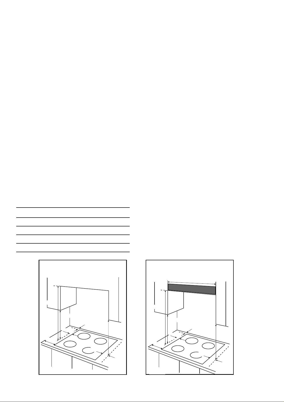
Before making the cut out in the worktop ensure that
there is a minimum distance of 55 mm. between the
rear edge of the hob and the wall. A minimum
distance of 100 mm. must be left between the side
edges of the hob and any adjacent cabinets or walls.
The minimum distance combustible material can be
fitted above the hob in line with the edges of the hob
is 420 mm. If it is fitted below 420 mm. a space of 50
mm. must be allowed from the edges of the hob.
The minimum distance combustible material can be
fitted directly above the hob is 700 mm.
Normal back right Hotplate Ø 145 mm 1040 W
Rapid front right Hotplate Ø 145 mm 1570 W
Rapid front left Hotplate Ø 180 mm 2090 W
Total rating 6270 W
INSTALLATION GUIDANCE INSTRUCTIONS
700 mm
100 mm
CLEARANCES REQUIRED
WHEN FITTING THE HOB
WITHOUT A COOKER HOOD ABOVE
420 mm
50 mm
55 mm
50 mm
420 mm
INSTALLATION GUIDANCE INSTRUCTIONS
650 mm
100 mm
CLEARANCES REQUIRED
WHEN FITTING THE HOB
WITH A COOKER HOOD ABOVE
600 mm
420 mm
50 mm
55 mm
50 mm
420 mm
FO 0813FO 0812
13
Page 13
Installation
IMPORTANT
This hob must be installed by qualified
personnel to the relevant British Standards.
The manufacturer will not accept liability,
should the above instructions or any of the
other safety instructions incorporated in
this book be ignored.
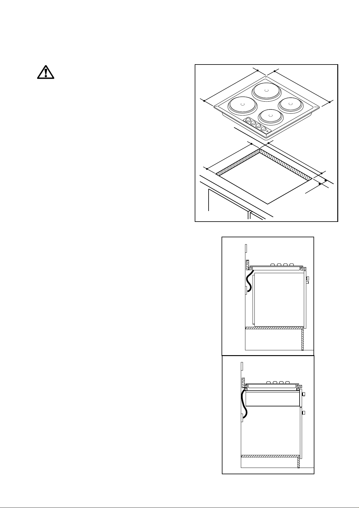
Cut Out Size
The dimensions of the cut-out are given in the
diagram.
Rectangular cut-out size for hob
580
510
560
480
55 min.
FO 2230
Building In
Building over a cupboard or drawer
If the hob is to be installed above a cupboard or
drawer it will be necessary to fit a heat resistant board
below the base of the hob on the underside of the
work surface.
It is also recommended to carry out the electrical
connection to the hob as shown in diagrams 1 and 2.
1
FLEX
OUTLET
FO 0763
2
ON/OFF SWITCH
ON/OFF SWITCH
FLEX
OUTLET
14
FO 0764
Page 14
Building o v er a kitchen unit with door
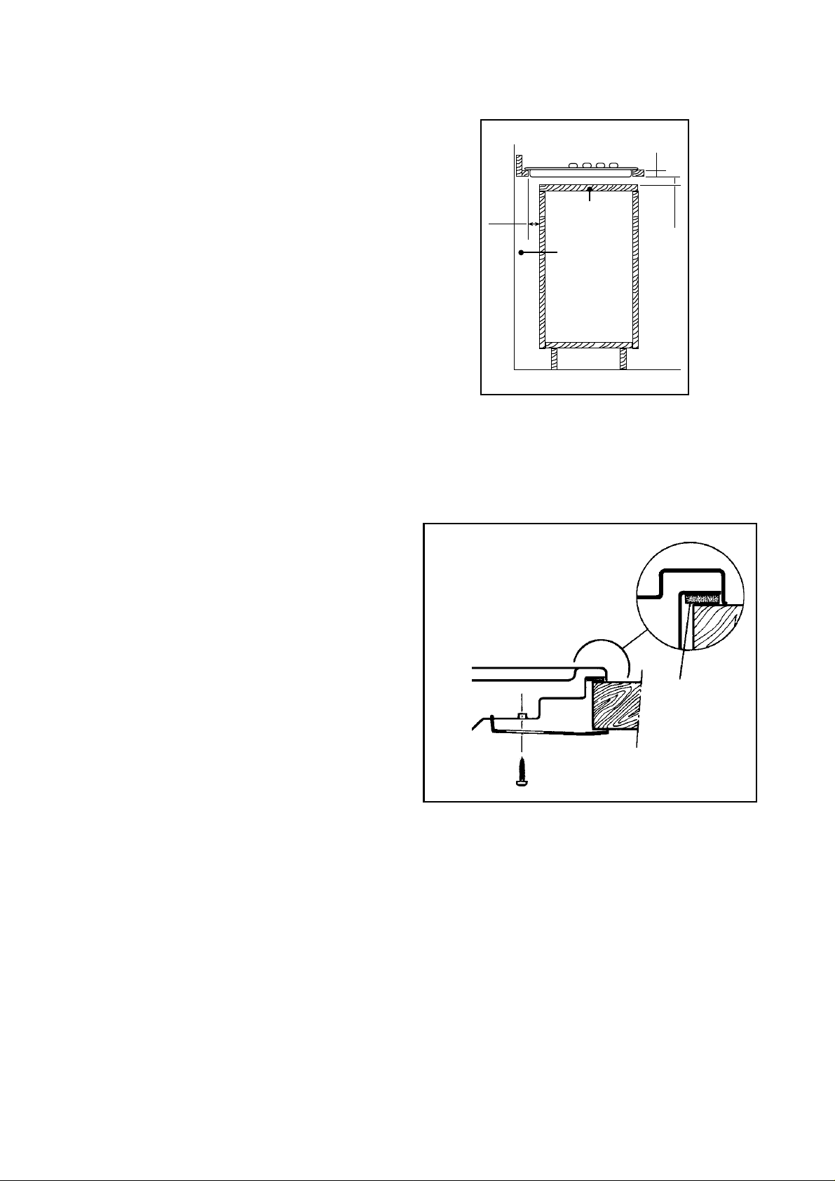
Proper arrangements must be taken in designing the
furniture unit, in order to avoid any contact with the
bottom of the hob which can be hot when in
operation. The recommended solution is shown in
diagram 3.
The panel fitted under the hob ("a") should be easily
removable to allow easy access if technical assistance
is needed. The space behind the kitchen unit ("b") can
be used for connections.
Fitting the hob to the worktop
Before fitting the hob into the cut out, an adhesive
sealing gasket supplied with the hob must be fitted to
the edge of the cut out. It is essential that no gaps are
left in this seal in order to prevent spillage near the
hob seeping into the cabinet below.
3
60
FO 1013
Dimensions are given in mm.
a
b
30
20 min
1) Place the sealing gasket all around the edge
☞
of the cut out.
2) Place the hob into the cut out and secure it by
means of the relevant fixing clamps and
screws, as shown in the diagram.
a
FO 0402
a) Sealing gasket
15
Page 15
Electrical connections
Any electrical work required to install this
hob should be carried out by a qualified
electrician or competent person, in
accordance with the current regulations.
THIS HOB MUST BE EARTHED.
The manufacturer declines any liability
should these safety measures not be
observed.
This hob is designed to be connected to a
230-240V 50Hz AC electrical supply.
Before switching on, make sure the electricity supply
voltage is the same as that indicated on the hob rating
plate. The rating plate is located on the bottom of the
hob. A copy is attached on the back cover of this
book.
The hob is supplied without supply cord. A 3 core
flexible supply cord must be fitted, in accordance
with the specification given in the relevant tables.
☞
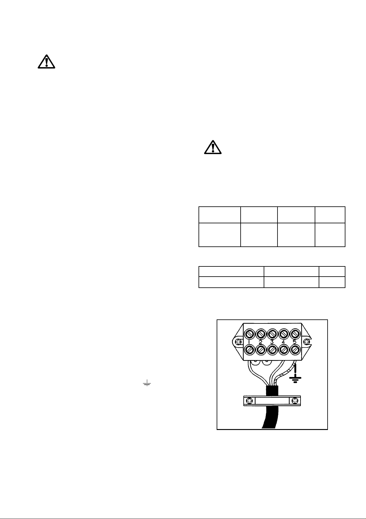
1) Remove the mains terminal cover plate from
the underside of the hob, to expose the mains
terminal block.
2) Loosen the two cable clamp screws and lift
the top section of the clamp enough to allow
the cable to be passed through.
The hob should be conncted to a double pole switch
with a minimum gap of 3 mm. between the switch
contacts and of a type suitable for the required load in
compliance with the current electric regulations. The
switch should be sited within 2m of the hob and be
easily accessible upon completion of the installation.
The switch must not break the yellow and green earth
cable at any point.
Ensure that the hob supply cord does not
come into contact with surfaces with
temperatures higher than 50 deg. C.
Supply Cable Specifications
For Uk use only
Connection Min. size Cable / flex Fuse
via Cable/flex type
• Cooker 6 mm
Control twin and
Circuit earth
For Europe use only
Min. size Cable/flex Cable / flex type Fuse
2.5 mm
2
2
PVC/PVC 30 A
H05 RR-F 30 A
3) Connect the red (live) wire to the terminal
which is marked with the number 1.
4) Connect the black (neutral) wire to the
terminal which is marked with the number 4.
5) After fitting a green or yellow/green sleeve
over the bare copper wire (earth wire), connect
the exposed end to the terminal which is
marked with the earth symbol
number 5.
NOTE:
The earth wire should be about 2 cm. longer
than the live and neutral wires.
6) Secure the cable by means of the clamp screws
and refit the terminal block cover.
or with the
FO 0488
16
Page 16
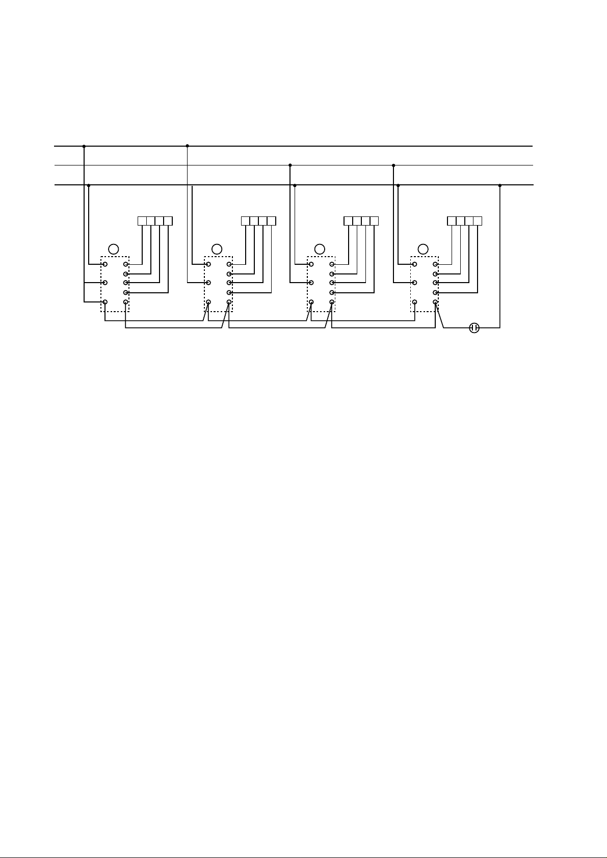
Wiring diagram
1
3
4
L
L
N
Ø 180 Ø 180 R Ø 145 R Ø 145
P
P
P
1
2
1
3
4
3
1
2
5
4321
P
P
P
2
2
1
3
4
3
1
2
5
4321
P
P
P
3
2
1
3
4
3
1
2
5
4321
P
P
P
4
2
1
3
4321
4
3
1
2
5
PLATE
17
 Loading...