

Page 1
Bedienungs- und Einbauanleitung für Einbau-
Kochmulden
Operating and Assembly Instructions for Built-in
Hobs
Notice d'utilisation et de montage des tables de
cuisson encastrables
Istruzioni per I'uso il montaggio de piani di
cottura
Gebruiksaanwijzing en inbouwinstructies voor
inbouw-kookplaaten
1
Page 2

Kombinationsmöglichkeiten
Tabelle für Maßekochmulden
Kochmulden EHE 642 X
Kombinations- EHE 642 W
möglichkeiten: EHE 642 K
Einbauherde EHE 642 B
EHE 642 EG
ALNO AHE 5031 NB X
AHE 5031 NW X
AHE 4071 NB X
AHE 4071 NW X
AHE 4071 NS X
AHE 4071NN X
ELECTROLUX EON 198 X X
EON 198 B X
EON 198 W X
EON 198 K X
EON 398 X X
EON 398 B X
EON 398 W X
EON 398 K X
ZANUSSI HN 212 B X
HN 212 W X
HN 212 S X
HN 212 X X
HM 214 B X
HM 214 W X
HM 214 S X
HM 214 X X
ZANKER ZKH 7012 B X
ZKH 7012 W X
ZKH 7012 S X
ZKH 7012 X X
ZKH 7012 G X
ZKH 7214 B X
ZKH 7214 W X
ZKH 7214 S X
ZKH 7214 X X
2
PNC NR.
941 628 111
941 628 112
941 628 113
941 628 114
941 628 115
Page 3
Installing the Hob
Check the hob for transport damage.
Do not install the hob if it shows signs
of damage. Be careful at the installation.
The Built-In-Hob correspond to heat
insulation class Y. In other words, a
kitchen unit taller than the hob unit
may be positioned on one side of it,
but not on both sides. On at least one
side, there must be no unit taller than
the hob unit itself.
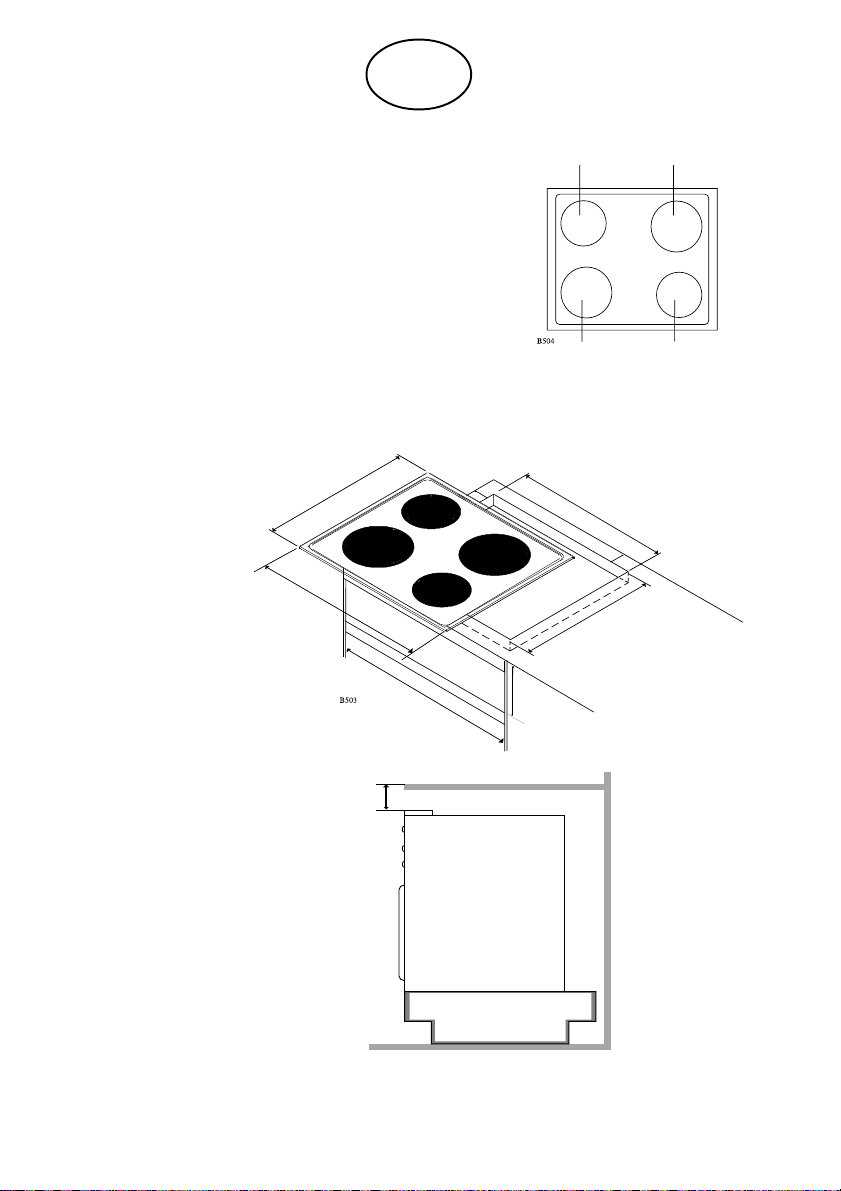
Cut the tabletop according to the prescribed dimensions or template (cut
exactly in the lines).
- The cutting measures are shown on
fig. 2.
GB
Fig. 1 40 mm
40
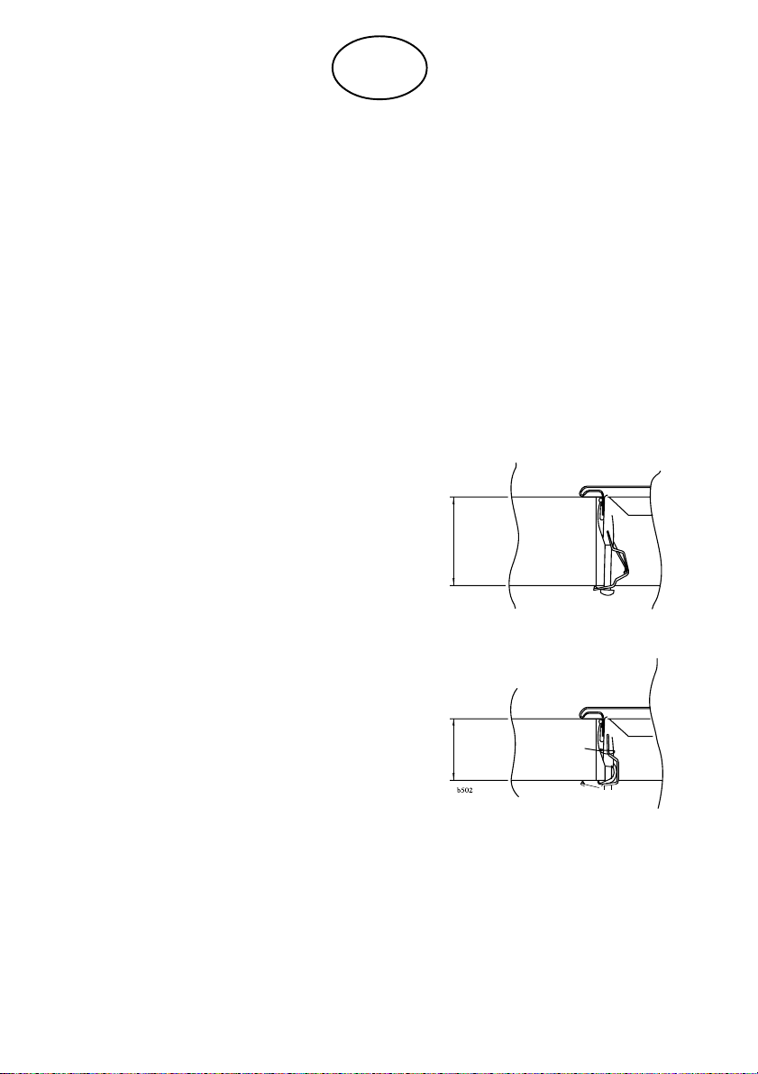
Check that the gasket is placed correctly and in continuity. Place the hob
in the cutout, properly centered.
Use a screwdriver, possibly for crossrecessed screws, for tightening the
fastening screws, starting at the
middle and proceding with the screw
diagonally opposite, tightening evenly
until the edge of the hob is held firmly
against the tabletop. Fig. 1.
28 mm
28
17
Page 4

GB
Attention!
Do not tighten more than necessary!
Do not use power tools without an
adjustable slipping clutch!
Important when dismantling the
Hob
Isolate the hob (for instance by
removing the fuses).
Electrical Installation
Connecting the hob with the special
control unit must be carried out by an
eletrician.
Hob and control unit shall be
disconnected from mains during the
installation
If the hob is connected by means of a
plug and socket, use always the
proper size.
If the hob is installed in combination
with an oven, the instructions for
connecting the oven control unit must
also be carefully followed.
The installation must ensure that live
parts cannot be touched incidentally.
If the hob is controlled by means of a
control unit, a partition should be
installed!
The distance between the bottom of
the hob and the carpentry below
should not be less than 110 mm.
If the hob is not connected with plug
and socket, the connection to the
supply shall be effected by means of
an isolating switch which breaks all
the phases with a minimum of 3 mm
contact gap.
The combinations between hobs/
build-in ovens/control units are shown
on the table annexed to the present
instructions.
The possibilities of conbining a hob
with oven/control unit should be
checked on the basis of the relevant
instructions for installation and use
before the apparatus is installed.
18
Page 5
GB
490
50
560
510
580
50
Min. 568
Min. 150
Min. 55
Descriptions of hobs:
1 = Quick-heating plate
145 Ø - 1500 W, 7 steps
2 = Standard plate
145 Ø - 1000 W, 7 steps
3 = Standard plate
180 Ø - 1500 W, 7 steps
With control unit
2 3
3 1
Fig. 2.
With build-in oven
Cutting measures as above
19
Page 6

GB
Notice!
The plates are provided with a
protective film, which shall be removed by heating before using the plates
for the first time. Leave the plates
with maximum heat on for 3 minutes.
Protect your plates against moisture
to avoid rusting. Do not place wet
utensils on the plates.
Kitchen utensils get hot on the hob, so
exert care.
Small children should not stay near.
Do not keep temperature sensitive or
inflammable materiale in drawers
immediately below the hob. -This
applies for example to detergents and
aerosols.
Important Notice for Enamelled
Hobs
Enamelled surfaces are hard as glass
and require special care. Hard and
sharp objects may damage enamel.
Enamelled surfaces may splinter if
heavy objects are dropped on them.
Fruit juice spots should be washed off
before they leave permanent stains.
The daily work in a kitchen will cause
scratches and dull spots. Such
blemishes are, of course, not covered
by our guarantee.
Use normal, mild household
detergents for cleaning the hob never
scouring powder.
Be careful with other kitchen tools
plugged in close to the hob. Their flex
should never touch the hot plates.
20
Page 7

36
325 87 8600 Rev.A-713
 Loading...