

Page 1

Built-in Hob - Encimera - Placa de encastrar
INSTRUCTION BOOKLET
MANUAL DE INSTRUCCIONES
INSTRUÇÕES DE UTILIZAÇÃO
35689-5501
Mod. EHC 320
CZ-HU-HR-SL-SK-RO-PL-ES-PT
Page 2
ENGLISH
For Your Safety
These warnings are provided in the interest of safety. You MUST read them carefully before installing or
using the appliance.
It is most important that this instruction book should be retained with the appliance for future reference.
Should the appliance be sold or transferred, always ensure that the book is left with the appliance in
order that the new owner can get to know the functions of the appliance and the relevant warnings.
During Operation
• This appliance has been designed to be operated by
adults and children under supervision. Young children
MUST NOT be allowed to tamper with the controls or play
near or with the oven.
• This appliance has been designed for cooking edible
foodstuff and to be used for domestic non-professional
purposes only. It must not be used for any other
purpose.
• It is dangerous to alter the specification in any way.
• For hygiene and safety reasons, this appliance should
be kept clean at all times. A build-up of fats or other
foodstuff could result in a fire.
• Accessible parts of this appliance may become hot
when it is in use. Children should be KEPT AWAY until it
has cooled.
• Under no circumstances should you attempt to repair
the appliance yourself. Repairs carried out by
unexperienced persons may cause injury or serious
malfunctioning. Refer to your local Zanussi Service
Centre. Always insist on genuine Zanussi spare parts.
• Ensure that all control knobs are in the OFF position
when not in use.
• Should you connect any electrical tool to a plug near
this cooking appliance, ensure that electric cables are
not in contact with it and keep them far enough from
the heated parts of this appliance.
• If the appliance is out of order, disconnect it from the
electric supply.
About Installation, Cleaning
and Manteinance
• Once you removed all packaging from the appliance,
ensure that it is not damaged and the electric cable is
in perfect conditions. Otherwise, contact your dealer
before proceeding with the installation.
• The manufacturer disclaims any responsability
should all the safety measures not be carried out.
The symbol on the product or on its packaging
indicates that this product may not be treated as household
waste. Instead it shall be handed over to the applicable
collection point for the recycling of electrical and electronic
equipment. By ensuring this product is disposed of
correctly, you will help prevent potential negative
consequences for the environment and human health,
which could otherwise be caused by inappropriate waste
handling of this product. For more detailed information
about recycling of this product, please contact your local
city office, your household waste disposal service or the
shop where you purchased the product.
Guide to Use the instructions
The following symbols will be found in the text to guide
you throughout the Instructions:
Safety Instructions
• It is mandatory that all operations required for the
installation are carried out by a qualified or competent
person, in accordance with existing rules and
regulations.
• Disconnect the appliance from the electrical supply,
before carrying out any cleaning or manteinance work.
These instructions are only for the countries stated by the symbol
printed on the front cover of this instruction book.
2
Step by step instructions for an operation
Hints and Tips
Environmental information
Page 3
Contents
For the User
For Your Safety 2
Description of the appliance 3
How to use 3
Hints and tips 4
Cleaning and maintenance 5
For the Installer
Technical Data 5
Instruction for the Installer 6
Electrical connection 6
Building In 7
Possibilities for insertion 8
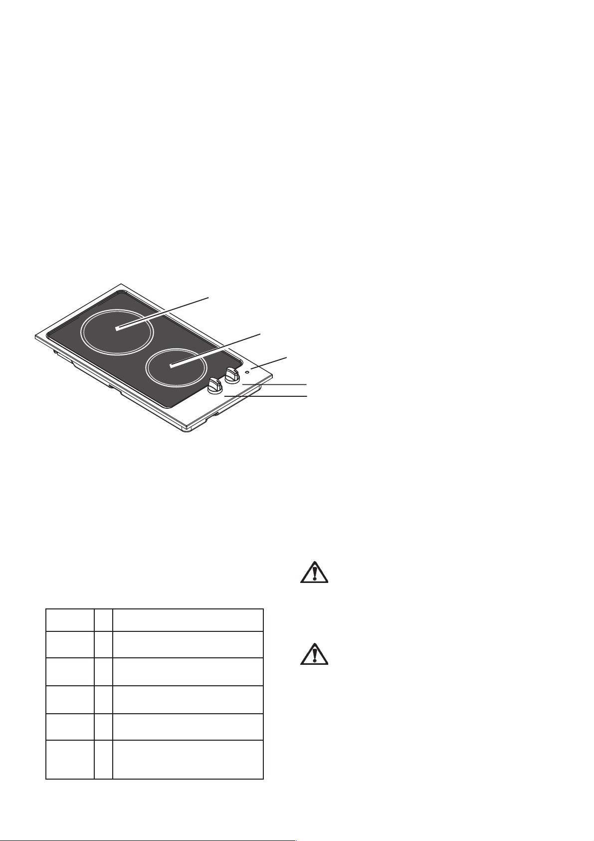
Description of the product
1
2
3
1 Rear cooking zone, 180 mm, 1700 W
2 Front cooking zone, 145 mm, 1200 W
3 Pilot lamp
4 Control knob for the rear cooking zone
5 Control knob for the front cooking zone
How To Use
Control knobs
The regulating of heat is graduation-free for both
plates on a scale from 1 to 6.
“1” Represents lowest heat
“6” Represents maximum heat.
“0” Represents “OFF”.
Setting 1
Setting 2
Setting 3
Setting 4
Keeping warm
Gentle simmering
Simmering
Frying / browning
4
5
Pilot light
Pilot light is activated when either of the zones are
turned on, and will remain on until the cooking
zones are switched off.
Do not use the ceramic hob if the glass
is damaged.
If a fault or crack appears during cooking
disconnect the hob immediately and contact
Electrolux Service.
Warning:
Aluminum foil and plastic utensils are not
to be placed on hot surfaces.
The surface may not be used for storage.
Setting 5
Setting 6
Bringing to the boil
Bringing to the boil / quick
frying / deep-frying
Do not stare at the heating units when in
operation.
3
Page 4

Advice and hints for using the
cooking zones
Adjust the cooking zones correctly.
Select the highest setting for the cooking zones
until the food is brought to the boil. Then reduce
the setting as far as possible, without the food
going off the boil.
Use level saucepans. An uneven saucepan
may increase the electricity consumption by up
to 50 per cent. Check whether your saucepans
have level bases by placing the item in question
upside down on a work top and positioning a
ruler on the base.
A curved base, both inwards and outwards, will
prolong the cooking time and increase the energy
consumption.
The saucepan should match the cooking zone
– or be slightly larger.
Cooking Zone Diameter of
pans to use
Rear cooking zone 180 mm
Front cooking zone 145 mm
Remember that a large saucepan can also hold
small quantities. If the diameter of the base is too
small, the energy consumption will increase,
and any food boiling over will burn onto the hot
cooking zone.
Saucepans with very shiny/bright bases will
prolong the cooking time slightly compared with
cooking utensils with matt/dark bases.
Use a tightly fitting lid on the saucepan. Without
a lid you use more than three times as much
electricity.
Do not slide saucepans across the surface of
the hob - always lift the pan when placing it on,
or removing it from the ceramic surface.
Wipe the bottom surface of the pots and pans
with a clean dry cloth before placing them on the
ceramic surface. This helps to reduce cleaning
and prevents scratching the hob glass.
Wipe off spills whilst the hob is warm.
4
Page 5
Cleaning and maintenance
Before any maintenance or cleaning can be
carried out, you must DISCONNECT the hob
from the electricity supply.
For reasons of hygiene and safety, the
cooking zones must be kept clean. Grease
stains and spilled food generate smoke when
heated, and can even cause fire.
Never use metal wool, metal sponges or
other abrasive cleaning agents.
Never use steam or a steam cleaning
machine to clean the appliance.
The ceramic glass hob
The decorative pattern on the ceramic surface
can become scratched and marred with use,
depending upon maintenance, but does not
adversely affect performance.
Such blemishes are not covered by the
warranty and do not affect the operation of
the hob.
A dirty ceramic hob decreases the heat transfer
between cooking zones and cookware.
After use the cooking zones should be wiped
with a damp cloth with washing up liquid.
For severe soiling you can follow these steps:
1. Remove stains etc., with a proper ceramic
hob scraper.
2. Make sure that the ceramic hob has cooled
down. Use a proper ceramic cleaning agent.
3. Wipe the ceramic hob clean with a damp cloth
or kitchen roll. Tough stains can be removed
by rubbing the stain hard with kitchen roll.
4. Wipe off remaining cleaning agent with a
damp cloth.
5. Wipe with a dry cloth, if required.
Make sure that the ceramic hob is dry when you
heat it up again. Ceramic hobs can develop
rainbow-like stripes if heated while damp.
Immediately scrape off stains caused by food
which has boiled over using a proper ceramic
hob scraper, spilled sugar, dishes containing
sugar (jam, juice, etc.), melted plastic and
aluminium foil while the ceramic hob is still hot.
If the ceramic hob is allowed to cool it may
become damaged.
Utensils which have been in contact with the
above-mentioned melted materials must be
cleaned throughly before used again on the
ceramic-top hob unit.
Defects in the ceramic surface which can
be related to the above are not covered
by the warranty.
Technical Data
Hotplate Rating
Rear Cooking Zone Ø 180mm 1,7 kW
Front Cooking Zone Ø 145mm 1,2 kW
Total Rating 2,9 kW
Electric Supply 230 V 50 Hz
Hob recess dimensions
Length 270 mm.
Width 490 mm.
Stainless steel surfaces
Clean the appliance after use with a soft cloth
well wrung out in warm water, use a small
amount of liquid detergent for stubborn soiling.
Stainless steel parts may become straw
coloured with use, use a proprietary stainless
steel cleaner to remove this straw discolouration.
This appliance complies with the following
E.E.C. Directives:
- 73/23 - 90/683 (Low Voltage Directive);
- 89/336
- 93/68 (General Directives)
and subsequent modifications.
MANUFACTURER:
ELECTROLUX HOME PRODUCTS ITALY S.p.A.
Viale Bologna, 298 I-47100 FORLÌ (Italy)
(Electromagnetical Compatibility Directive);
5
Page 6

Instruction for the Installer
The following instructions about installation
and maintenance must be carried out by
qualified personnel in compliance with the
regulation in force.
The appliance must be electrically
disconnected before all interventions. If any
electric supply to the appliance is required to
carry out the work, ensure all the necessary
precautions are followed.
The side walls of the unit in which the hob is
going to be installed, must not exceed the
height of the working top.
Avoid installing the appliance in the proximity
of inflammable materials (e.g. curtains, tea
towels etc.).
Electrical Connection
The appliance is designed to be connected to 230 V
monophase electricity supply.
The connection must be carried out in compliance with
the laws and regulations in force.
Before the appliance is connected:
1. check that the main fuse and the domestic installation
can support the load (see the rating label);
2. check that the power supply is properly earthed in
compliance with the current rules;
3. check the socket or the double pole switch used for
the electrical connection can be easily reached with
the appliance built in the forniture unit.
The appliance is supplied with a connection cable. This
has to be provided with a proper plug, able to support the
load marked on the identification plate. To connect the
plug to the cable, follow the recommendation given in
Fig.1. The plug has to be fitted in a proper socket.
If connecting the appliance directly to the electric system,
it is necessary that you install a double pole switch
between the appliance and the electricity supply, with a
minimum gap of 3 mm. between the switch contacts and
of a type suitable for the required load in compliance with
the current rules.
The connection cable has to be placed in order that, in
each part, it cannot reach a temperature 90 °C higher than
the room temperature.
The brown coloured phase cable (fitted in the terminal
block contact marked with "L") must always be connected
to the network phase.
Neutral
Earth (yellow/green)
Fig. 1
Replacement of the connection cable
The replacement of the connection cable requires the
specific equipment of a technician.
In this case, only cable type H05V2V2-F T90 must be
used. The cable section must be suitable to the voltage
and the working temperature.
The yellow/green earth wire must be approximately 2
cm longer than the phase wires (Fig. 1).
6
Page 7

Building In
Fig. 2
Dimensions are given in millimetres
510
290
650 MIN.
490
55
270
40÷50
These hobs can be inserted in a built-in kitchen unit whose
depth is between 550 and 600 mm. The hobs dimensions
are shown in Fig. 2.
Installation and assembly
These hobs can be installed in a kitchen unit with an
opening for insertion whose dimensions are shown in
Fig. 3.
The edge of the cut out must have a minimum distance
from the rear wall of 55 mm.
If there are side walls, or sides of the furniture unit near
the hob, the cut out edges must have a minimum distance
of 100 mm.
Hanging forniture units or hoods must be placed at 650
mm minimum from the hob.
Carry out the building in of the hob as follows:
1. Place the sealing gasket (Fig.4 - “A”) all around the
edge of the cut out.
2. Fit the hob in the cut out and push it down until it
comes in contact with the kitchen top surface. Then
remove the excess sealing.
240
140
550 MIN
30
591
Fig. 3
REMOVE
3. To remove the hob from the cut-out, lift the edge of the
hob by means of the edge of a screw-driver.
If several 30cm hob are to be installed side by
side into the same cut out, an assembly kit
including a support side bracket and
supplementary sealings is available at our After
Sales Centres. The relevant installation instructions
are supplied within the kit package.
FO 0548
Fig. 4
7
Page 8
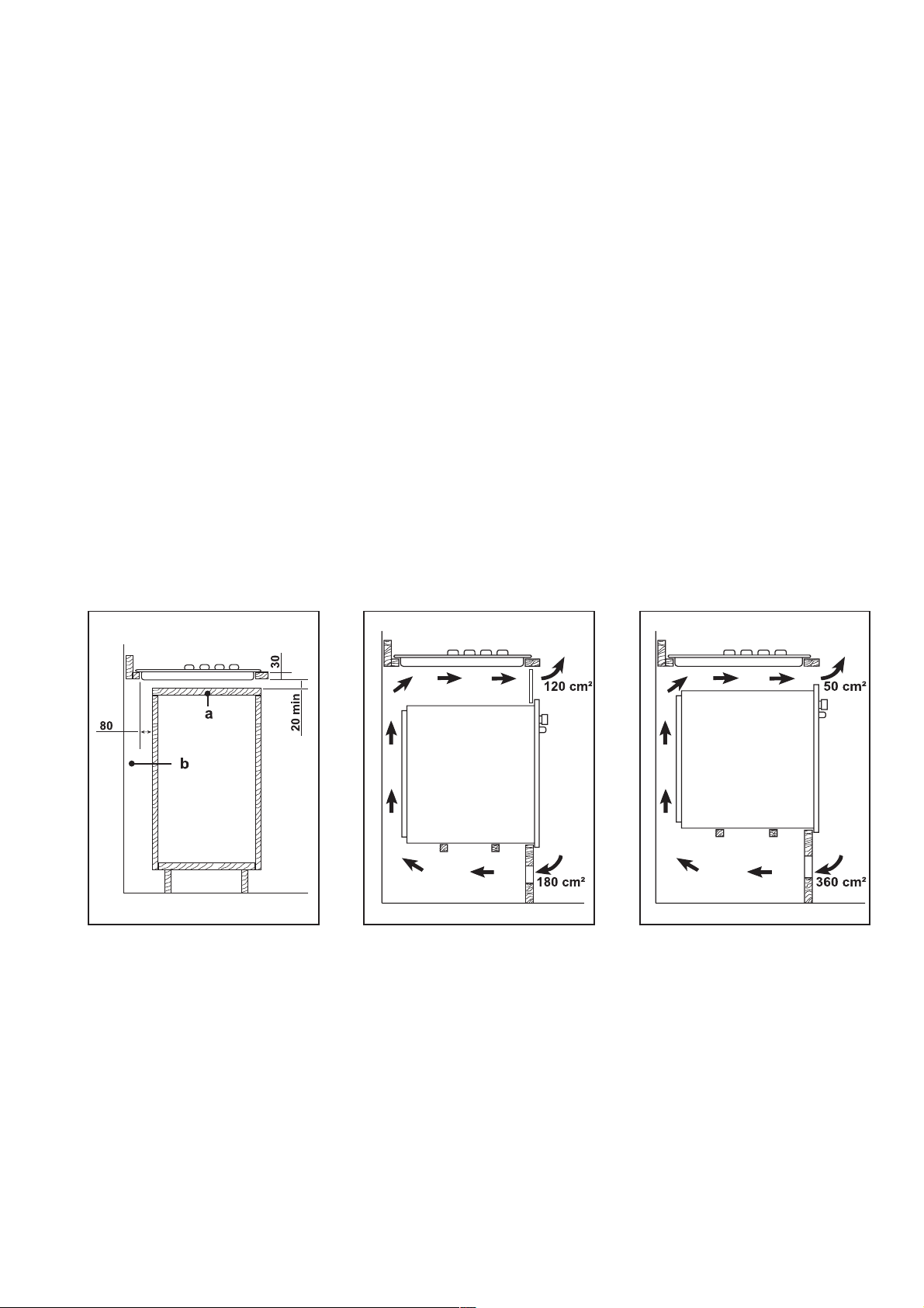
Possibilities for insertion
Building over a kitchen unit with
door
Proper arrangements must be taken in designing the
furniture unit, in order to avoid any contact with the bottom
of the hob which can be hot when in operation. The
recommended solution is shown in diagram 5.
The panel fitted under the hob ("a") should be easily
removable to allow easy access if technical assistance
is needed. The space behind the kitchen unit ("b") can
be used for connections.
Kitchen unit with oven
The hob recess dimensions must comply the indication
given in Fig. 3 and the kitchen unit must be provided with
proper openings to allow a continuous supply of air.
Suggestions to ensure a proper ventilation are shown in
Figs. 6 e 7.
The electrical connection for the hob must be separate
from the electrical connection for the oven, to ensure
safety and to allow an easy removal of the oven from the
unit, if necessary.
Fig. 5 Fig. 6 Fig. 7
FO 2166
a) Removable panel
b) Space for connections
FO 0938FO 0939
8
 Loading...