

Page 1

instruzioni per l'uso
manual de instrucciones
пдзгЯет чсЮузт
EGL4401X
EGL4400X
Page 2
XXX XXX XXX - 00 - 20102005
Page 3
Use & Care Manual
Assembly Instrucions Included
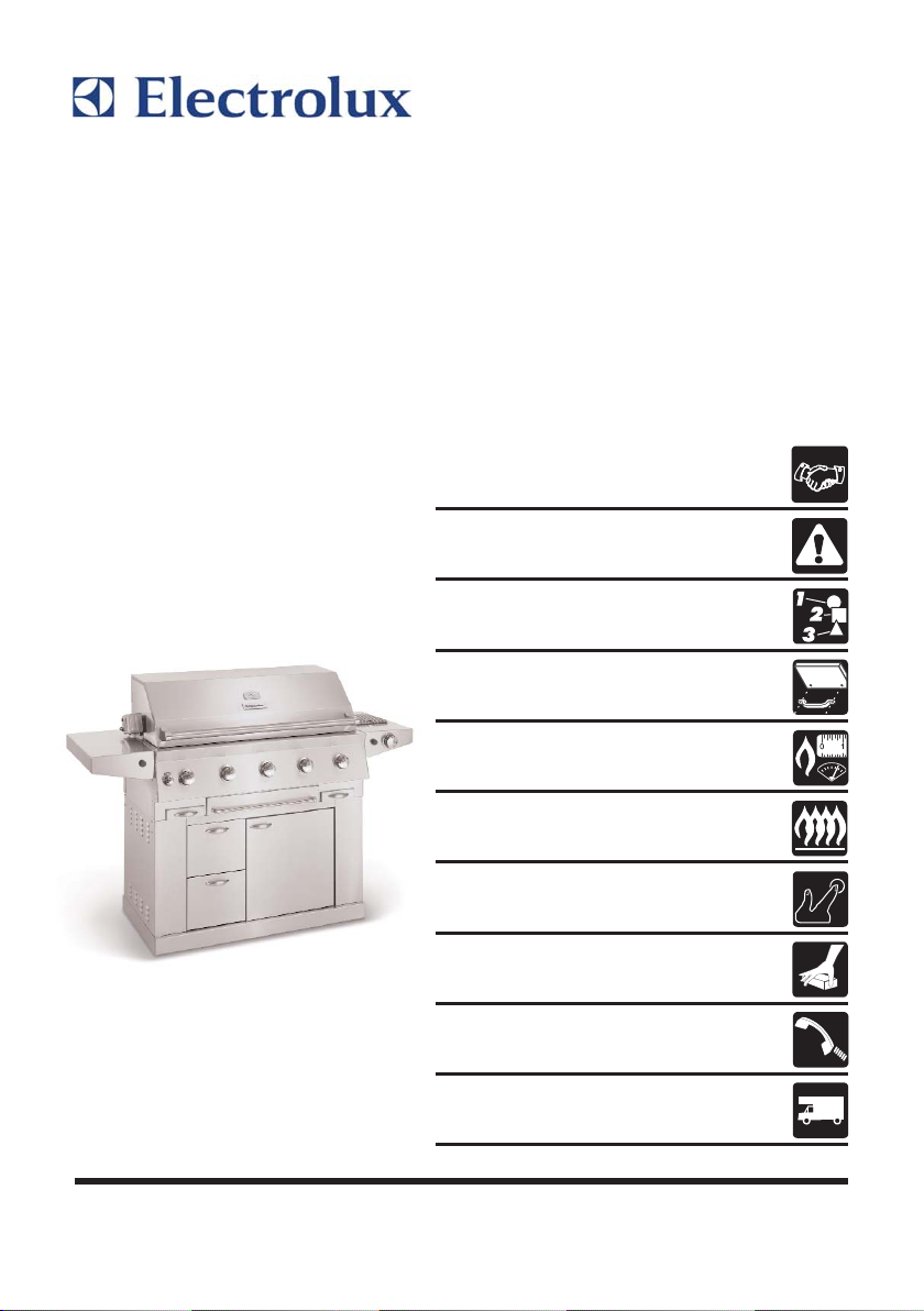
Outdoor Grill
with Electronic Ignition
READ AND SAVE THESE INSTRUCTIONS
Welcome & Congratulations . . . 2
General Safety Instructions . . . 3
Grill Features . . . . . . . . . . . . . . . 5
Grill Assembly
Side shelf
Built-In Instructions . . . . . . . 6-11
Gas Requirements
Leak Testing . . . . . . . . . . . . 12-14
Using the Gril . . . . . . . . . . . . . . 15
Lighting the Grill
Using the Rotisserie
& Side Burning . . . . . . . . . . 16-21
Care and Maintenance . . . . . . 22
Troubleshooting . . . . . . . . . 23-25
Warranty . . . . . . . . . . . . . . . . . . 26
Page 4

WELCOME TO THE WORLD OF ELECTROLUX
Thank you for choosing a first class product from Electrolux, which hopefully
will provide you with lots of pleasure in the future. The Electrolux ambition is to
offer a wide variety of quality products that make your life more comfortable.
You find some examples on the cover in this manual.
Please take a few minutes to study this manual so that you can take
advantage of the benefits of your new machine.
We promise that it’ll make your life a little easier. Good luck!
2
Welcome & Congratulations
Page 5

3
General Safety Instructions
GENERAL INFORMATION FOR COOKING APPLIANCES
You MUST read these warnings carefully before installing or using the
appliance. If you need assistance, contact our Customer Care Centre.
Keep this instruction book for future reference and ensure it is passed on to any
new owner.
INSTALLATION
It is mandatory that all operations required for the installation are carried out
by a qualified or competent person, in accordance with existing rules and
regulations.
Remove all packaging before using the appliance
Once you removed all packaging from the appliance, ensure that it is not
damaged and in perfect condition. Otherwise, contact your dealer before
proceeding with the installation.
Do not attempt to modify the appliance in any way.
It is dangerous to alter the specification in any way.
Any gas installation must be carried out by a registered competent person,
and in accordance with existing rules and regulations.
The manufacturer will not accept liability, should the above instructions or any
of the other safety instructions incorporated in this book be ignored.
CHILD SAFETY
This appliance is designed to be operated by adults. The appliance gets hot
when it is in use. Do not allow children to play near or with the appliance.
Children should be kept away until it has cooled. Children can also injure
themselves by pulling pans or pots off the appliance.
DURING USE
Ensure a good ventilation around the appliance. A poor air supply could cause
lack of oxygen.
Do not use this appliance if it is in contact with water. Do not operate the
appliance with wet hands.
Ensure the control knobs are in the ‘OFF’ position when not in use.
When using other electrical appliances, ensure the cable does not come into
contact with the hot surfaces of the appliance.
Never leave the appliance unattended when cooking with oil and fats.
Never use plastic or aluminium foil dishes on the appliance.
Perishable food, plastic items and aerosols may be affected by heat and
should not be stored above or below the hob unit. Never use the appliance as a
working space. Do not store things on the appliance.
Page 6

4
General Safety Instructions
For hygiene and safety reasons, this appliance should be kept clean at all
times. A build-up of fats or other foodstuff could result in a fire.
Take care when frying food in hot oil or fat, as the overheated splashes could
easily ignite.
Carefully supervise cookings with fats or oil, since these types of foodstuff can
result in a fire, if over-heated.
If the appliance is out of order, disconnect it from the gas supply.
Never use steam or high pressure steam cleaners to clean the appliance.
SERVICE
This appliance should only be repaired or serviced by an authorised Service
Engineer and only genuine approved spare parts should be used. Repairs carried
out by unexperienced persons may cause injury or serious malfunctioning.
ENVIRONMENTAL INFORMATION
After installation, please dispose of the packaging with due regard to safety
and the environment.
When disposing of an old appliance, make it unusable, by cutting off the
cable. The symbol on the product or on its packaging indicates that this product
may not be treated as household waste. Instead it shall be handed over to the
applicable collection point for the recycling of electrical and electronic equipment.
By ensuring this product is disposed of correctly, you will help prevent potential
negative consequences for the environment and human health, which could
otherwise be caused by inappropriate waste handling of this product. For more
detailed information about recycling of this product, please contact your local city
office, your household waste disposal service or the shop where you purchased
the product.
Page 7
5
Grill Features
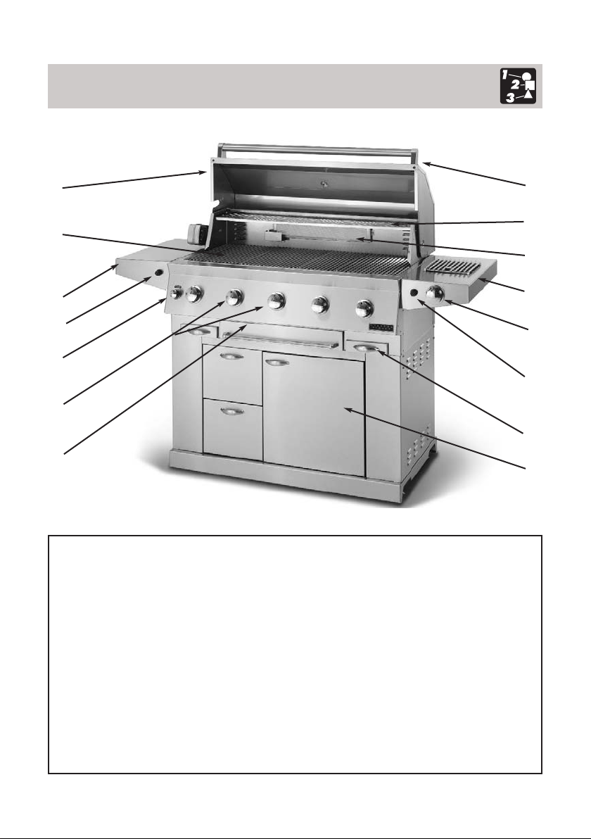
1. Roll top grill hood
2. Grilling/Cooking surface
3. Side Shelf
4. Control knob: back
infrared burner
5. Control knobs: main burners
6. Warming drawer
7. Handle
8. Warming shelf
9. Infrared back burner
10.Electronic ignitors: main,
rear infrared & side burner
11. Cart with door
12. Drip Pans
13. Side Burner
14. Control knob: Side Burner
1
2
3
10
4
5
6
7
8
9
13
14
10
12
11
Page 8
6
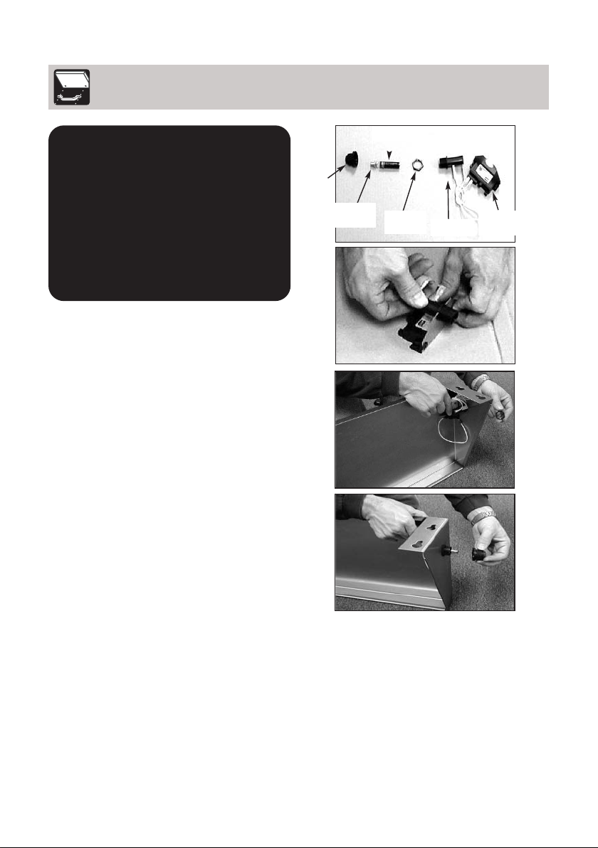
IGNITOR ATTACHMENT
1. Remove the ignitor cap, spring
assembly, battery and lock nut from
ignitor. (See Fig. 1)
2. Insert the threaded section of the
ignitor into the U-shaped cut out of
the ignitor mounting bracket.
(See Fig. 2)
3. Insert the threaded section of the
ignitor through the hole in the shelf
and secure to shelf using the lock
nut. (Use the ignitor assembly
diagrams to determine which
ignitor goes with which shelf
depending on grill model.) Tighten
Securely. (See Fig. 3)
4. Re-insert the battery, positive side
first, and spring assembly and
attach the ignitor cap. (See Fig. 4)
5. Repeat above steps for second
ignitor on the Side Burner.
IMPORTANT: Remove all
protective plastic film from
stailess steel parts prior to
assebly/use. This film is
installed at the factory to
prevent damage that could
occur during shipment and
handling.
Grill Assembly
Battery
Mounting
Bracket
Cylinder
Cap
Locking
Nut
Spring
Fig. 1
Fig. 2
Fig. 3
Fig. 4
Page 9
7
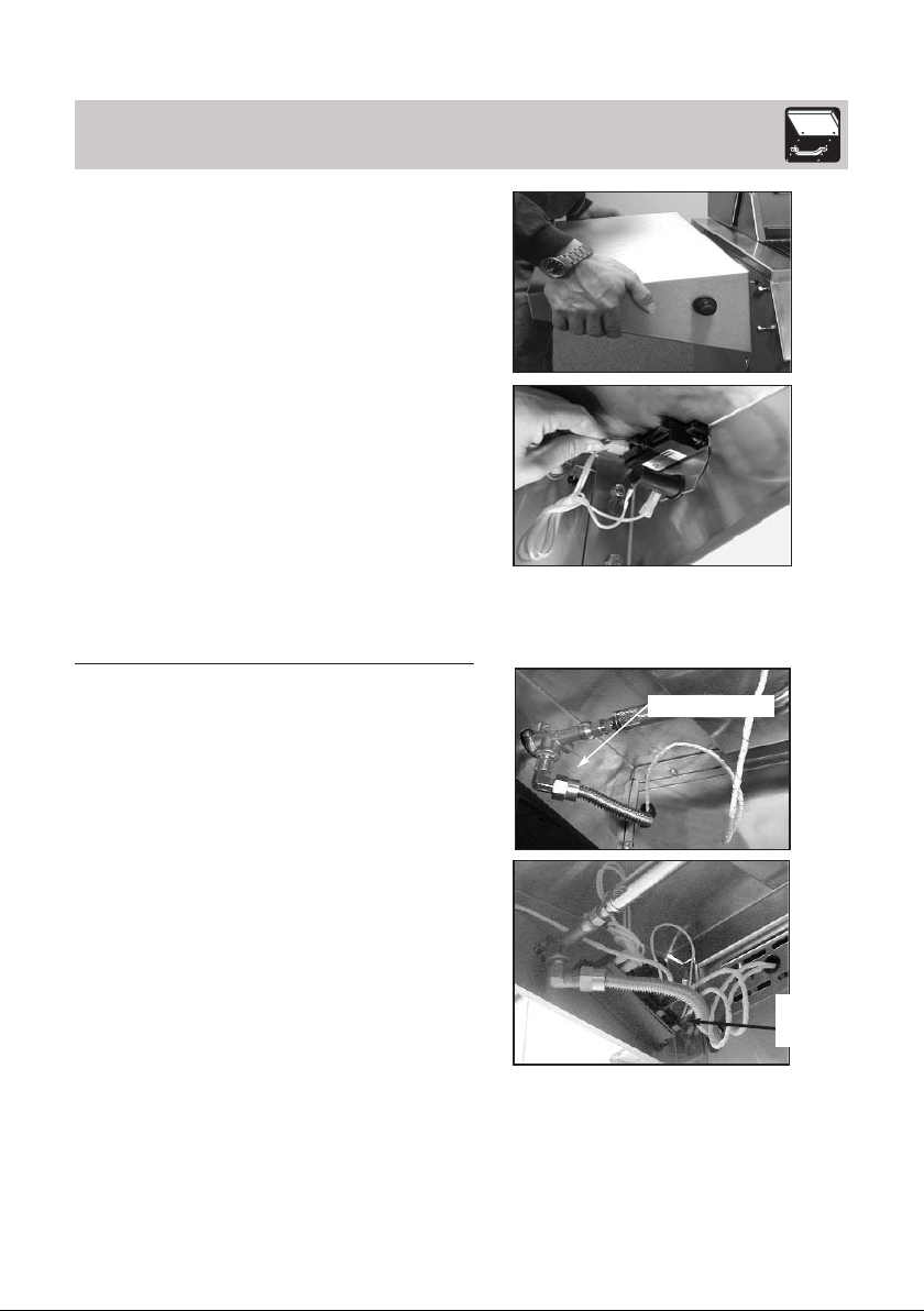
SIDE SHELF AND SIDE BURNER
ATTACHMENT
1. Loosen the bolts on the side of
the grill attach the shelf by
allowing the bolt fall through the
large opening in the the keyhole
slots. Then slide the shelves
downward until the bolts are
resting the top of the key hole
slots. Tighten the shelf bolts.
(See Fig. 5)
2. Attach the wires coming out from
the the grill to the ignitor
terminals. (See Fig. 6)
NOTE: It does not matter which wire
goes terminal on the four wire
ignitor
3. Attach the side burner by
allowing the heads to fall
through the large opening
bottom of the keyhole slots.
Then slide side burner downward
until the bolts resting against the
top of the key hole Tighten all of
the side burner bolts.
4. Attach the Flex Line coming from
the the grill to the fitting on the
bottom of Side Burner.
(See Fig. 7)
5. Attach the ignitor wires coming
out side of the grill to ignitor
terminals. (See Fig. 8)
NOTE: It does not matter which wire
goes terminal on the four wire
ignitor
Side shelf
Attach to fitting
Ignitor
wires
hookup
Fig. 5
Fig. 6
Fig. 7
Fig. 8
Page 10

8
Grill Assembly
INTERIOR PARTS INSTALLATION
1. Check to make sure the bottom
Flavor Grids are correctly installed
in the cutouts and around the
ignitors, as they may have shifted
during shipment.
(See Fig. 9)
2. Insert the second row of Flavor
Grids into cutouts with triangle
ridges facing up.
(See Fig. 10)
3. Install cooking grates on the ledges
provided on the grill to create your
cooking surface. (placing the one
with a thumb hole in the middle)
(See. Fig. 11)
4. Place warming shelf on support
brackets by setting it flat across
brackets allowing the two holes to
line up with the stops on each
bracket. (See Fig. 12)
Bottom Flavor Grids
in between burners
Fig. 9
Fig. 10
Fig. 11
Fig. 12
Page 11

9
PLANNING AND DESIGN
Start by identifying the number and size of components you want to include:
Grill, side burner, access doors for storage or other items you may wish to furnish
such as: refrigerator, sink, warming drawer. Countertops must be constructed
with non-combustible, outdoor-safe materials. Consider outdoor lighting to
illuminate after-dark Grilling. Review the drawings on the following pages to
determine the exact dimensions and items needed for a built-in Grill. Keep in
mind that the gas line hook-up is on the right hand side for the main Grill head.
The structure, Grill and support items must be kept level throughout the
installation to ensure proper operation.
LOCATION
Take into account convenience and visual impact as well as traffic flow, wind
exposure, and the site’s structural suitability. The Grill should never be placed in
an enclosed area without an approved ventilation system, or beneath a
combustible overhang. Because the Grill exhausts to the rear, it should never be
located in front of a window or less than 30 cm from hard-to-clean surfaces.
We recommend keeping your gas supply lines as short as possible for best
performance. To ensure a perfect fit, we strongly recommend that you have all
components on hand prior to final construction.
CLEARANCE TO NON-COMBUSTIBLE CONSTRUCTION
For your safety a minimum of 8 cm clearance from the back of the Grill to
non-combustible construction is required.
You should allow at least 15 cm side clearance to non-combustible
construction. The Electrolux Grill can be placed directly adjacent to noncombustible construction below the cooking surface.
The Electrolux Grill: model EGL4401X can be installed as a
built-in Grill. If installed as a built-in Grill, the Grill surround
must be constructed of Non-combustible material.
Built-In Instructions
for model EGL4401X
WARNING
!
Page 12

10
OUTBOARD IGNITOR PLATE INSTALLATION
The electronic ignitor requires a standard size electrical box, (available at a
local hardware store), with a minimum depth of 6 cm to be mounted in the
structure. It should be placed on the left front or left side of the built-in island,
with the center of the ignitor button no more than ca 10 cm from the Grill. The
ignitor plate (included with the model EGL4401X), fits over the standard electrical
box once mounted in the structure. (See drawing on following page). The ground
wire for the ignitor needs to be grounded to a metal structure in order for the
ignitor to work.
UTILITIES
The optional rotisserie kit requires a 230 volt electric supply and GFI
receptacle, that should be installed by a qualified electrical technician. If your plan
includes a sink, arrange for your plumber to run a water line to the site.
Built-In Instructions
for model EGL4401X
Page 13

11
Additional Requirements:
* Gas connection cut out in floor support needs to be 10 cm wide x 23 cm long, set 5 cm back
from front edge.
* Ignitor cutout is equal to a standard electrical outlet with a minimum depth of 6 cm.
* If using a backsplash apron or rear wall, locate electrical service on the left hand side for
rotisserie motor connection.
* A minimum clearance of 30 cm from the back must be maintained between the grill
and any combustible construction such as wood siding of a residence, 8 cm minimum
for non-combustible construction.
Built-In Instructions
for model EGL4401X
Side cutouts are needed on each side to feed
ignitor wires to the ignitor plates and allow
access to side gas connections .
(Size: 25 cm high x 12.5 cm long, set 1
back from front edge)
GFI Electrical outlet
for rotisserie motor
A
B
*Required Ignitor cutout
for front or side mount
*A minimum 8 cm clearance is
required between the back of the
grill hood and a non-combustible
surface.
Built-in dimensions without using a Trim Kit
Single
44
Access
Grill
A
112 cm
112 cm
53 cm
B
33 cm
C
D
N/A
E
N/A
N/A
N/A
N/A
46 cm
47 cm
Dual
Access Door
Door
N/A
N/A
N/A
92 cm
47 cm
*Gas
Cutout
Floor Support
area for grill
E
Note: Make sure to use a
non-combustible base and
sides for the structure
70 cm Min.
C
5 cm
Opening
D
for access
door(s)
90 cm Max.
Distance to center of ignitor
button from side of gril
IGNIT OR PLATE
INSTALLATION
counter top
Built-in dimensions using a Trim Kit
44
Grill
A
112 cm
112 cm
54 cm
B
22 cm
C
D
N/A
E
N/A
Single
Access
Door
N/A
N/A
N/A
46 cm
47 cm
Access Door
92 cm
47 cm
ca 10 cm
Grill
ca 10 cm
Dual
N/A
N/A
N/A
Page 14

12
For the correct installation of the
connection kit to the grill it is necessary
to screw the exit junction of the kit
placed at the end of the flexible hose
to the gas inlet of the grill. In order to
obtain a proper sealing of the junction
it is necessary to complete the
screwing using a adjustable wrench
(see Fig.13)
The connection kit is designed
in a way that do not require additional
gaskets to guarantee a proper sealing.
After having installed the connection kit
verify the correct sealing of the gas
connections following the Pre
Operation Leak Testing instructions
contained in this manual.
Gas Requirements
GENERAL INFORMATION
Never attach an unregulated gas line
to the appliance. Connection to an
unregulated gas line can cause
excessive heat or fire.
Verify the type of gas supply to be used,
Liquid Propane or Butane (L.P.).
NOTE: Always have a qualified service
technician perform difficult
conversions or modifications.
All pipe sealants must be an
approved type and resistant to the
actions of L.P. gases. Never use pipe
sealant on flare fittings. All gas
connections should be made by a
competent qualified service technician
and in accordance with local codes and
ordinances. The installation of this grill
must conform with local codes.
L.P. GAS INSTALLATION
Electrolux Gas Grills that are set to
operate with L.P. gas come with a gas
bottle connection kit in a separate box.
(Note:Only use gas bottle connection kit
supplied with the grill or replacement kit
specified by Electrolux).
This assembly is designed to
connect directlythe grill to a standard
L.P. tank. L.P. tanks are not included
with the grill and can be purchased
separately at an indipendednt dealer.
For the correct installation of the
connection kit to the L.P. tank please
refer to the specific instructions coming
with the connection kit.
Fig. 13
Page 15

13
Gas Requirements
L.P. TANK INFORMATION
Never use a dented or rusted L.P. tank or cylinder with a damaged valve.
Cylinders must not be stored in a building, garage, or any other enclosed area.
L.P. TANK USE
• When turning the L.P. tank on, make sure to open the valve SLOWLY two (2)
complete turns to insure proper gas flow.
• When not in use, gas supply cylinder valve is to be in the “OFF” position.
• The tank supply system must be stored upright to allow for vapor withdrawal.
• The regulator and hose assembly must be inspected before each use of the
grill. If there is excessive abrasion or wear or if the hose is cut, it must be
replaced prior to the grill being used again.
• Cylinders must be stored in accordance with local codes.
• Do not store a spare L.P. gas cylinder under or near the grill.
Page 16

14
Pre Operation
GENERAL INFORMATION
Although all gas connections on the grill are leaked tested at the factory prior
to shipment, a complete gas tightness check must be performed at the
installation site due to possible mishandling in shipment, or excessive pressure
unknowingly being applied to the unit. Periodically check the whole system for
leaks, or immediately check if the smell of gas is detected.
BEFORE TESTING
Do not smoke while leak testing. Extinguish all open flames. Never leak test
with an open flame.
Mix a solution of equal parts mild detergent or liquid soap and water.
TESTING
1. Turn off the burner control knobs.
2. Turn the top knob of the fuel supply cylinder counterclockwise (right to left)
one rotation to open.
3. Apply the soap solution to connections of the fuel supply assembly. If no soap
bubbles appear, there is no gas leak. If bubbles form at the connections, a
leak is detected. (If a leak is detected, immediately turn off the gas supply,
tighten any leaking fittings, turn gas on, and receck).
4. Turn off the knob on the fuel supply cylinder.
5. Turn on the burner control knobs for a moment to release the pressure in the
hose, then turn the control knobs back off.
6. Wash off soapy solution with cold water and towel dry.
NOTE: If you cannot stop a gas leak turn off the gas supply call the dealer you
purchased the appliance from.
If necessary, replace the faulty part with a manufacture recommended
replacement part. When leak testing this appliance, make sure to test and
tighten all loose connections. A slight leak in the system can result in a
low flame, or a hazardous condition.
Check all gas supply fittings before each use and each time the gas supply
cylinder is connected to the regulator.
Leak test any time a part of the gas system is replaced. Perform a leak test at
least once a year whether or not the L.P. gas supply cylinder has been
disconnected.
Page 17

15
Using the Grill
GRILL LOCATION
Do not use the grill in garages, breezeways, sheds or any enclosed area.
Never operate the grill in enclosed areas as this could lead to a carbon monoxide
buildup, which could result in injury or death. Place the grill on a level surface.
Avoid moving the grill while it is operation.
NOTE: The grill will operate best if it is not facing directly into the wind.
Clearance to combustible construction - A minimum of 30 cm from the sides
and back must be maintained from the gas grill above and below the cooking
surface to adjacent vertical combustible construction.
Clearance to non-combustible construction - A minimum of 8 cm clearance
from the back of the grill to non-combustible construction is required for the lid to
fully open.
GENERAL RULES
Do not leave the grill unattended while cooking!
1. Make sure the grill has been leak tested and is properly located.
2. Light the grill burners using the instructions on this page.
3. Turn the control knobs to “High” and preheat the grill for 10 minutes.
4. Place the food on the grill and cook to the desired doneness.
Adjust heat setting between “High” and “Low” if necessary.
5. Allow grill to cool down and clean the drip tray after each use.
* Keep any electrical supply cords and the fuel supply hose away from any
heated surfaces.
* The location of the burner tube with respect to the the orifice is vital
for safe operation. Check to ensure the orifice is inside of the burner
tube before using your grill. This is Very Important.
Page 18

16
BEFORE LIGHTING
Important!
Before Lighting...
Check the gas supply line for cuts,
wear or abrasion.
Always keep your face and body as
far away from the grill as possible when
lighting.
GRILL BURNER LIGHTING
This unit comes equipped with (2)
electronic starters and (4) electrodes.
The electronic starter located on the
right shelf lights the Side Burner.
The electronic starter on the left shelf
lights the Main Burners, which are
controlled by Knobs 1, 2, 3, 4 & 5.
The left electronic starter also lights
the Back Infrared Burner.
LIGHTING THE GRILL WITH
ELECTRONIC IGNITORS
Always open the lid before
attempting lighting.
Push and turn one of the control
knobs counter clockwise to the “HIGH”
position and immediately press the
electronic ignitor button. You’ll hear a
snapping sound. It may be necessary to
hold the electronic starter button for
about 4 seconds. If the burner does not
light in 4 seconds, turn the knob to OFF
and wait 5 minutes before trying again.
Repeat above steps to light
remaining burners. (See Fig. 14)
Lighting the Grill
Fig. 14
Do not attempt to “Light”
the grill if the odor of gas
is present!!
Back
Infrared
Knob
nr. 5
Knob
nr. 4
Knob
nr. 3
Knob
nr. 2
Knob
nr. 1
WARNING
!
Page 19

17
Lighting the Grill
MATCH LIGHTING
If by chance the electronic ignitor
does not light the burner, the burner
may be lit with a match. Keep your
face as far away from the Grill surface
as possible and pass a lit, long stem
match through the spaces in the Grill
rack to the ports of the back crossover
burner between the flavor grids.
Position the match near the burner
ports and push and turn the control
knob counter clockwise to the “HIGH”
position. (See Fig. 15)
NOTE: If the grill will not light after
several attempts see the
Troubleshooting section of this
manual. Turn the control knobs
to the OFF position when not
in use.
CONTROL KNOB
LAYOUT:
The control knob
bezel has stamped
markings for the
HIGH and LOW
settings. Turning
the knob so the
arrow faces the left
is the HIGH
setting. Turning
the knob so the
arrow faces down
is the LOW setting.
Fig. 15
Page 20

18
Using the Rotisserie & Side Burners
Note: ROTISSERIE KIT is an accessory and must be
purchased separately and is only available on some markets.
The grill rotisserie system is designed to cook items from the back using
infrared heat. The rotisserie burner is an infrared type which provides intense
searing radiant heat. Preferred by chefs over other cooking methods, this intense
heat is magnificent for searing in the natural juices and nutrients found in quality
cuts of meats.
Once lit, the rotisserie burner will reach cooking temperatures in 1 minute.
The orange/red glow will even out in about 5 minutes. The rotisserie motor is
equipped with metal gears and is capable of turning up to 9 kg of food. The
motor is mounted on a bracket on the left side of the grill by sliding the motor
over the bracket with the cord facing the back of the grill. Make sure the motor is
straight prior to operating.
ELECTRICAL GROUNDING INSTRUCTIONS
This appliance (rotisserie motor) is equipped with a
grounding plug for your protection against shock
hazard and should be plugged directly into a properly
grounded receptacle. Do not cut or remove the
grounding prong from this plug.
WARNING
!
Page 21

19
ATTACHING THE ROTISSERIE
The motor is mounted on a bracket on the left
side of the grill by sliding the motor over the
bracket with the cord facing the back of the grill.
With the rotisserie motor in place and plugged
into an electrical outlet it is now ready to operate.
After installing rotis rod handle, slide one of the
meat forks onto the rod. (prongs facing away from
the handle)
Push the rod through the center of the food,
then slide the second meat fork onto the rod.
(prongs toward the food). Center the food to be
cooked on the rod, then push the meat forks firmly
together. Tighten the wing nuts. It may also be
necessary to wrap food with butcher’s string,
(never use nylon or plastic string) to secure loose
portions.
Once the food is secure, insert the pointed end
of the rotis rod into the motor assembly and rest
the other end on the support on the right-hand
side of the Grill.
(If needed remove the cooking grates for more
room.). Turn the power switch to the “On” position
to start the rotisserie motor.
NOTE: Remove the rotisserie when not in use.
Remove warming shelf when using rotis.
Using the Rotisserie & Side Burners
Note: ROTISSERIE KIT is an accessory and must be
purchased separately and is only available on some markets.
Page 22

20
ROTISSERIE LIGHTING
Open the lid. Push and turn the
control knob counter clockwise to the
“HIGH” position. Wait 5 seconds. Then
press and hold the electronic ignitor
button. You’ll hear a snapping sound. If
the burner does not light in 4 seconds,
turn the control knob to OFF and wait
5 minutes before trying again.
Once lit, turn the control knob to the
desired setting. (See Fig. 16)
(If the ignitor does not function, the
burner can be lit by holding a lit match
to the burner while the control knob is
turned counter clockwise to “HIGH”.)
(See Fig. 17)
NOTE: After the first use the stainless
steel around the burner will
darken. This is a normal
occurrence of the non-rusting,
stainless steel used on the
grill. The infrared panel will
also darken after initial use.
This is a normal occurrence.
Fig. 16
Fig. 17
Using the Rotisserie & Side Burners
Note: ROTISSERIE KIT is an accessory and must be
purchased separately and is only available on some markets.
NOTE: Do Not operate the
main burners and
infrared back burner
at the same time.
Page 23

21
Fig. 18
SIDE BURNER LIGHTING
Push and turn the control knob to
the “HIGH”position and immediately
press and hold the electronic ignitor
button. You’ll hear a snapping sound.
It may be necessary to hold the
electronic starter button for about 4
seconds. If the burner does not light in
4 seconds, turn the knob to the “OFF”
position and wait 5 minutes before
trying again. Repeat above steps to
light remaining burners. (See Fig. 18)
MATCH LIGHTING
If by chance the electronic ignitor
does not light the burner, the burner
may be lit with a match. Keep your
face as far away from the burner as
possible and place a lit, long stem
match through the spaces in the grate
to the ports of the burner. Position the
match near the burner ports and push
and turn the control knob to the
“HIGH”position.
Using the Rotisserie & Side Burners
Page 24

22
DRIP TRAY
The drip tray located below the grill, inside the cart, should be cleaned
periodically to prevent heavy buildup of debris.
NOTE: Allow the drip tray to cool before attempting to clean.
COOKING GRATES
The cooking grates can be cleaned immediately after cooking is completed
and after turning off the flame.
Wear a barbecue mitt and scrub the cooking grates with a damp cloth. If the
grill is allowed to cool down, cleaning the grates will be easier if removed from the
grill and cleaned with a mild detergent.
STAINLESS STEEL
The grill is made from a non-rusting stainless steel. After initial usage, areas of
the grill may discolor from the intense heat given off by the burners, this is
normal.
Purchase a mild stainless steel cleaner and rub in the direction of the grain of
the metal. Specks of grease can gather on the surface of the stainless steel and
bake on to the surface and give a worn appearance. For removal use an nonabrasive oven cleaner in conjunction with a stainless cleaner.
NOTE: Always scrub in the direction of the grain.
REAR INFRARED BURNER:
Please light and burn the rear infrared burner at least once a month to ensure
there is not a build-up of debris or grease on the burner. This will ensure the
ceramic burner will continue to operate as it should.
Care and Maintenance
Page 25

23
GENERAL TROUBLE SHOOTING
You should inspect the burners at least once a year or immediately if any
of the following conditions occur:
The smell of gas in conjunction with the burner flames appearing yellow.
The Grill does not reach temperature.
The burners make a popping noise.
The Grill heats unevenly.
BEFORE CALLING CUSTOMER SERVICE
If the Grill does not function properly, use the following checklist.
Troubleshooting
Page 26

24
PROBLEM
Grill will not light when
the igniter button is pushed.
Low heat with knob
in “High” position.
SOLUTION
After opening tank valve, be sure one
of theGrill control knobs is on high for
at least 4 seconds while pushing
ignitor button.
Check tank fuel level.
Check for loose wire connections.
Remove the cooking grates and flavor
grids. Push ignitor button, and check
for spark on tip of electrode.
Check to see if debris is blocking
the electrode sparks.
Check battery/replace battery.
Attempt to match light the burner.
Disconnect gas line at tank, then
reconnect.
Check for proper gas supply
and pressure.
Check for low fuel level.
Check for kinks in supply line.
If only one burner appears low, clear
burner ports of any obstructions.
Pre-heat Grill for a full 10 minutes.
Disconnect gas line at tank, then
reconnect.
Troubleshooting
Page 27

25
PROBLEM
Flame is erratic
Flare-Ups
Burner flame is yellow or orange,
in conjunction with the odor
of gas.
Cart door does not align properly
with cart
SOLUTION
Check gas connection.
Fuel level may be low.
Grill may be in need of cleaning.
Check flavor grids and cooking grates
for excess build-up.
Ensure Grill is not placed directly in
path of wind.
Be sure the drip tray is clean.
(do not use aluminum foil in drip tray)
Check the burner inlet for
obstructions.
Grill may be in a windy area. Move to
a less windy area if possible.
Loosen the four bolts that attach grill
head to cart. Slide grill head either to
the left or right until door is aligned
properly. Retighten the bolts.
SPIDER AND INSECT WARNING
Spider and insects can nest in the burners of this or any other Grill and cause
the gas to flow from the front of the burner. This is very dangerous condition
which can cause a fire to occur behind the valve panel, thereby damaging the
Grill and making it unsafe to operate. We recommend you check at least once a
year to be safe.
Troubleshooting
Page 28

26
Warranty
STANDARD GUARANTEE CONDITIONS
We, Electrolux, undertake that if within 12 months of the date of the purchase
this Electrolux appliance or any part thereof is proved to be defective by reason
only of faulty workmanship or materials, we will, at our option repair or replace the
same FREE OF CHARGE for labour, materials or carriage on condition that:
• The appliance has been correctly installed and used only on the electricity
supply stated on the rating plate.
• The appliance has been used for normal domestic purposes only, and in
accordance with the manu-facturer’s instructions.
• The appliance has not been serviced, maintained, repaired, taken apart or
tampered with by any per-son not authorised by us.
• All service work under this guarantee must be un-dertaken by a Service Force
Centre.
• Any appliance or defective part replaced shall be-come the Company’s
property.
• This guarantee is in addition to your statutory and other legal rights.
Home visits are made between 8.30am and 5.30pm Monday to Friday.
Visits may be available outside these hours in which case a premium will
becharged.
Page 29

27
Warranty conditions
EXCLUSIONS
This guarantee does not cover:
• Damage or calls resulting from transportation, im-proper use or neglect, the
replacement of any light bulbs or removable parts of glass or plastic.
• Costs incurred for calls to put right an appliance which is improperly installed
or calls to appliances outside the United Kingdom.
• Appliances found to be in use within a commercial environment, plus those
which are subject to rental agreements.
• Products of Electrolux manufacture which are not marketed by Electrolux.
EUROPEAN GUARANTEE
If you should move to another country within Europe then your guarantee
moves with you to your new home subject to the following qualifications:
• The guarantee starts from the date you first pur-chased your product.
• The guarantee is for the same period and to the same extent for labour and
parts as exists in the new country of use for this brand or range of products.
• This guarantee relates to you and cannot be trans-ferred to another user.
• Your new home is within the European Community (EC) or European Free
Trade Area.
• The product is installed and used in accordance with our instructions and is
only used domestically, i.e. a normal household.
• The product is installed taking into account regulations in your new country.
Before you move please contact your nearest Customer Care centre, listed
below, to give them details of your new home. They will then ensure that the local
Service Organisation is aware of your move and able to look after you and your
appliances.
France Senlis +33 (0) 3 44 62 20 13
Germany Nürnberg +49 (0) 800 234 7378
Italy Pordernone +39 (0) 800 11 7511
Sweden Stockholm +46 (0) 20 78 77 50
UK Luton +44 (0) 8705 950 950
Page 30

Service and Spare Parts
If the event of your appliance requiring service, or if you wish to purchase
spare parts, please contact Service Force by telephoning:
Your telephone call will be automatically routed to the Service Force Centre
covering your post code area. For the address of your local Service Force Centre
and further information about Service Force, please visit the website at
www. serviceforce.co.uk
Before calling out an engineer, please ensure you have read the details under
the heading “What to do if...“
When you contact the Service Force Centre you will need to give the following
details:
1. Your name, address and post code.
2. Your telephone number.
3. Clear and concise details of the fault.
4. The model and serial number of the appliance (found on the rating plate)
5. The purchase date.
Please note that a valid purchase receipt or guaran-tee documentation is
required for in-guarantee serv-ice calls.
CUSTOMER CARE
For general enquiries concerning your Electrolux ap-pliance, or for further
information on Electrolux prod-ucts please contact our Customer Care
Department by letter or telephone at the address below or visit our website at
www.electrolux.co.uk.
(*) Calls may be recorded for training purposes 0870 5 929 929
Customer Care Department
Major Appliances
Electrolux
Addington Way
Luton
Bedfordshire, LU4 9QQ
Tel: 08705 350350 (*)
For Customer Service in the
Republic of Ireland
please contact us at the address
below:
AEG/ Electrolux Group (Ire) Ltd
Long Mile Road/ Dublin 12
Republic of Ireland
Tel: +353 (0) 1 4090753
Email: service.eid@electrolux.ie
28
 Loading...