

Page 1

User manual
EFP 632
UK
Page 2

Contents
Safety warnings 3
for the installer 3
for the user 3
Introduction 4
Extractor version 4
Filter Version 4
Description of the Appliance 4
Control Panel 5
Correct ventilation 5
Maintenance and care 6
Cleaning 6
Metal grease filter 6
Open the metal grease filter 6
Charcoal filter 7
Changing the light bulb(s) 7
Technical Specifications 8
Special accessories 8
Installation 8
Unpacking 8
Placement 8
Electrical connection 8
Mounting accessories included 9
Installation 10
Before you use the cooker hood we recommend that you read through the whole user manual giving a direct
description of the cooker hood and its functions.
To avoid the risks, that are always present when you use a product driven by electricity, it is important that the
cooker hood is installed correctly and that you read the safety instructions carefully to avoid misuse and hazard.
Save the instruction manual and keep it available at use of the cooker hood.
2
Page 3

Safety warnings
for the installer
• When used as an extractor unit, the hood must
be fitted with a 120mm diameter hose.
• When installing the hood, make sure you
respect the following minimum distance
from the top edge of the cooking hob/ring
surfaces:
electric cookers 430 mm
gas cookers 650 mm
coal and oil cookers 700 mm min.
• The national Standard on fuel-burning systems
specifies a maximum depression of 0.04 bar in
such rooms.
• The air outlet must not be connected to
chimney flues or combustion gas ducts. The air
outlet must under no circumstances be connected to ventilation ducts for rooms in which
fuel-burning appliances are installed.
• It is advisable to apply for authorization from
the relevant controlling authority when
connecting the outlet to an unused chimney flue
or combustion gas duct.
The air outlet installation must comply with the
regulations laid down by the relevant
authorities.
• When the unit is used in its extractor version, a
sufficiently large ventilation hole must be
provided, with dimensions that are
approximately the same as the outlet hole.
• National and regional building regulations
impose a number of restrictions on using hoods
and fuel-burning appliances connected to a
chimney, such as coal or oil room-heaters and
gas fires, in the same room.
• Hoods can only be used safely with appliances
connected to a chimney if the room and/or flat
(air/environment combination) is ventilated
from outside using a suitable ventilation hole
approximately 500-600 cm
possibility of a depression being created during
operation of the hood.
• If you have any doubts, contact the relevant
controlling authority or building inspector’s
office.
• Since the rule for rooms with fuel burning
appliances is “outlet hole of the same size as
the ventilation hole”, a hole of 500-600 cm2,
which is to say a larger hole, could reduce the
performance of the extractor hood.
• If the hood is used in its filtering function, it
will operate simply and safely in the above
conditions without the need for any of the
2
large to avoid the
aforementioned measures.
• When the hood is used in its extractor function,
the following rules must be followed to obtain
optimal operation:
— short and straight outlet hose
— keep bends in outlet hose to a minimum
— never install the hoses with an acute angle,
they must always follow a gentle curve only
— keep the hose as large as possible
(preferably the same diameter as the outlet
hole).
• Failure to observe these basic instructions will
drastically reduce the performance and increase
the noise levels of the extractor hood.
for the user
• Always cover lighted elements, to prevent
excess heat from damaging the appliance. In
the case of oil, gas and coal fired cookers it is
essential to avoid open flames.
• Also, when frying, keep the deep frying pan on
the cooker top/cooker under careful control.
• The hot oil in the frying pan might ignite due to
overheating.
• The risk of self-ignition increases when the oil
being used is dirty.
• It is extremely important to note that
overheating can cause a fire.
• Never carry out any flambé cooking under
the hood.
• Always disconnect the unit from the power
supply before carrying out any work on the
hood, including replacing the light bulb (take
the cartridge fuse out of the fuse holder or
switch off the automatic circuit breaker).
• It is very important to clean the hood and
replace the filter at the recommended
intervals. Failure to do so could cause grease
deposits to build up, resulting in a fire
hazard.
• The appliance is not intended for use by young
children or infirm persons without supervision.
• Young children should be supervised to ensure
that they do not play with the appliance.
• WARNING - Ensure that the appliance is
switched off before replacing the lamp to avoid
the possibility of electric shock.
3
Page 4
Introduction
• The hood is supplied as an extractor unit and
can also be used with a filtering function by
fitting one charcoal filter (special accessory).
• You will need original AEG charcoal filter KLF
60/80 for this function (see Special
Accessories).
Extractor version
• In this version fumes are extracted to the
outside via a hose.
Filter Version
• The air is filtered through a charcoal filter and
returned to the kitchen.
• You will need an original AEG KLF60/80
charcoal filter for the filtering function. (See
Special Accessories).
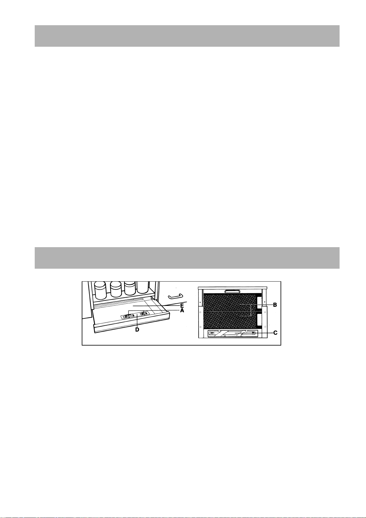
Description of the Appliance
Fig. 1
A = Switches (Motor, light)
B = Grease filter
C = Light
D = Control panel
E = Vapour catcher (Extractible)
4
Page 5

Control Panel
• The switches are arranged on the upper right side of the vapour catcher. (Fig. 1 - E).
The numbers and symbols have the following meanings (Fig. 2 - from left to right):
1
= blower set 1
2
= blower set 2
= blower set 3
3
= blower set 4
4
= light
= light OFF
= light ON
The blower is controlled by shifting the sliding
switch.
The extractor part (vapour catcher) of the hood is
used to switch the blower on and off when the
appliance is switched on (Motor).
When the vapour catcher of the appliance is
withdrawn (without preceding disengagement of
the hood via the switches), the set fan output is
automatically re-engaged.
If the extractor part is re-inserted without operation
of the switches, first the blower is switched off.
The lighting can be separately switched on and off
with the sliding switch.
Turn the hood on a few minutes before you start
cooking then you will get an underpressure in the
kitchen. It should be left on after cooking for about
15 minutes or until all odours have disappeared.
Correct ventilation
If the cooker hood is to work correctly there must
be an under pressure in the kitchen. It is important
to keep the kitchen windows closed and have a
window in an adjacent room open
5
Page 6

Maintenance and care
The hood must always be disconnected from the electricity supply before beginning any
maintenance work.
Cleaning
• Warning: always disconnect the hood from the
mains power supply before cleaning it.
Never insert pointed objects in the motor’s
protective grid.
• Wash the outside surfaces using a delicate
detergent solution. Never use caustic detergents
or abrasive brushes or powders.
• Only ever clean the switch panel and filter
grille using a damp cloth and delicate
detergents.
• It is extremely important to clean the unit and
change the filters at the recommended intervals.
Failure to do so will cause grease deposits to
build up that could constitute a fire hazard.
Metal grease filter
• The purpose of the grease filters is to aspirate
grease particles which form during cooking and
it must always be used, either in the external
evacuation or internal recycling function.
Attention: the metal grease filters must be
removed and washed, either by hand or in the
dishwasher, every four weeks.
Warning
• Failure to observe the instructions on cleaning
the unit and changing the filters will cause a
fire hazard. You are therefore strongly
recommended to follow these instructions.
• The manufacturer declines all responsibility for
any damage to the motor or any fire damage
linked to inappropriate maintenance or failure
to observe the above safety recommendations.
Open the metal grease filter
• Pull the lateral handles towards the bottom, by
placing them in the front and removing the
filter. Fig. 3.
Hand washing
• Soak grease filters for about one hour in hot
water with a grease-loosening cleaner, then
rinse off thoroughly with hot water. Repeat the
process if necessary. Refit the grease filters
when they are dry.
Dishwasher machine
• Place grease filters in dish washer. Select most
powerful washing programme and highest
temperature, at least 65°C. Repeat the process.
Refit the grease filters when they are dry.
When washing the metal grease filter in the
dishwasher a slight discoloration of the filter
can occur, this does not have any impact on its
performance.
• Clean the inner housing using a hot detergent
solution only (never use caustic detergents,
abrasive powders or brushes).corrosifs ou de
brosses à récurer!).
Fig. 3
6
Page 7

Charcoal filter
CLOSED
OPEN
CLOSED
OPEN
• The charcoal filter should only be used if you
want to use the hood in its filtering function.
• To do this you will need an original AEG
charcoal filter (see special accessories).
• Replacing the charcoal filter
The charcoal filter must normally be replaced at
least once every year. This filter cannot be
washed or regenerated.
To guarantee proper absorption of odours the
working volume of the charcoal must be
proportionate to the hood air flow. In this case
the high quality of the charcoal will ensure
efficient odour removal for approximately one
year, assuming that the hood is used normally.
For this reason you should always use original
AEG filters only, making sure they are replaced
when necessary .
• Mounting
1. Pull out the vapour catcher (Fig. 1 - A).
2. Remove first the rear then the front grease
filters.
3. Insert the charcoal filter into the lugs of the
holding frame above using the 2 red clips to
retain it below, press the red clips inwards, and
insert the charcoal filter in the holding frame.
Fig. 4.
• Dismounting:
1. Press both red lugs upwards (towards the
inside of the housing) and remove the charcoal
filter downwards.
2. Clean the internal housing only with warm
washing-up liquid’ suds (never use any abrasive
cleaners, brushes, or scouring agents).
• Always specify the hood model code number
and serial number when ordering replacement
filters. This information is shown on the
registration plate located on the inside of the
unit.
• The charcoal filter can be ordered from the
AEG technical assistance service.
Fig. 4
Changing the light bulb(s)
• Disconnect the unit from the mains power
supply.
• Pull out the drawer.
• Open the lamp cover support.
• Replace the old light bulb with a new light bulb
of the same kind.
• Replace the lamp cover support.
• If the light does not come on, make sure the
bulb has been screwed in correctly before
contacting the technical assistance service.
Fig. 5
7
Page 8

Technical Specifications
Dimensions (in cm) Height 39,5
Width 59,8
Depth 27,5
Lighting: 2 x 40 W (E14)
Grease filter 2
Maximum absorbed power 320 W
We reserve the right to generate constructive and chromatic modifications as required by technological growth.
Special accessories
Charcoal filter KLF 60/80 E-Nr. 610 899 421
Installation
Unpacking
Check that the cooker hood has no damages.
Transportation damages should immediately be
reported to the one responsible for the transport
Damages, faults and eventually missing details
should immediately be reported to the seller.
Take care of the packing material so that small
children cannot play with it.
Placement
The hood is to be mounted on the wall.
When installed, the hood must be not less than
43cm. above electric burners or 75 cm. above gas
or mixed-fuel burners (fig. 6).
Electrical connection
Safety warnings for the electrician
Before connecting the appliance to the power
supply, check that the voltage indicated on the
rating plate corresponds to the mains power supply
available. Appliances fitted with a plug can be
connected to any standard power socket within
easy access.
Should it be necessary to provide a fixed
connection, the hood must only be installed by an
electrician authorised by the local electricity
board. When installing, an omnipolar disconnector
with a distance of at least 3 mm between contacts
must be provided.
The manufacture declines all responsibility for
malfunctions resulting from failure to comply with
the above instructions.
Min
43 cm
Min
75 cm
Fig. 6
Electrical connection
220-240 V – by means of fixed power cable with
plug.
(Fixed connection of the appliance must only be
carried out by an authorised electrician.)
8
Page 9

Installation
Mounting accessories included
1 deflector
4 spacer discs
1 metal screws 2,9x13
2 metal screws 2,9x9,5
2 metal screws 3x9
4 wood-screws 4,5 x 16 mm
1 flange Ø 120 mm
Preparing the wall unit - Extractor version
• The hood is supplied as an extractor unit.
Before installing the hood, drill a hole in the
roof of the wall unit
(see fig. 7). This hole is to allow passage of the
outlet pipe and the power cable, and to facilitate
servicing.
• The wall unit must have a minimum body depth
(without door) of 300 mm with recessed light
screen and min. 370 mm with flush-mounted
light screen. The unobstructed internal height
must be at least 370 mm.
190
172
238
Outlet hole (extractor-filter version)
• When used as an extractor unit, the hood must
be fitted with a 120mm diameter hose.
• Fix the flange on the hood outlet hole. Bajonett
attachment. Fig. 8a.
Filter version only
• Fix the deflector on the outlet hole of the hood.
Fig. 8b.
Spice rack
• If a spice rack is to be incorporated in front of
the hood, a minimum distance of 5 mm must be
provided between the front edge of the fume
extractor hood and the spice rack wall (this air
gap being necessary for air circulation).
• The upper part of the spice rack rear wall
should be detachable (access for exhaust air
hose or adjustment of furniture housing).
Fig. 7
Fig. 8a Fig. 8b
9
Page 10

Installation
Installing the fume extractor hood in the wall
unit - extractor version (Filter version with
charcoal filter)
• Apply the drilling template to the inside wall of
the wall unit on the right and left sides, and
mark out and predrill Ø 2 mm mounting holes
as well as 2 x Ø 6 mm - 5 mm depth holes for
the mounting claws (installation aids).
• Unscrew the ventilation grill mounted on the
appliance (1 screw), apply the exhaust air union
prepared to the required exhaust air diameter,
and twist it to the right to its fullest extent (so
that it is retained).
• Fully withdraw the vapour catcher of the hood.
• Important: Detach and insert the grease filters
only when the vapour catcher is fully
withdrawn.
Remove the grease filters. First remove the rear
and then the front grease filter.
• For 16 mm side walls:
Fit two spacers per side in corespondance with
fixing points.
Mount the hood with 4 x Ø 4 mm screws. Fig.
9.
• Insert the hood in the furniture housing and
engage both mounting claws (installation aids)
on the right and left sides in the side wall of the
wall unit and firmly hold the hood for further
mounting.
Then fix the hood with the 4 x Ø 4 mm screws
supplied.
• Refit the grease filters. Push-in the vapour
catcher.
Fig. 9
Adjusting the extractor part (E - Fig. 1) - Fig.
10
On wall units with a body depth of 275 mm to 335
mm, the vapour catcher depth can be adjusted as
follows:
• Remove both grease filters.
• Loosen the screws on both end-stop brackets
and set the vapour catcher depth (min. 275 mm,
max. 335 mm).
• Refit the screws.
• Refit the grease filters.
Fig. 10
10
Page 11

11
Page 12

LI1Y6A Ed.05/02
 Loading...