

Page 1
Instructions Manual
Manuel d’Instructions
Bedienungsanleitung
Gebruiksaanwijzing
EFP 60271
Page 2

EN
Instructions Manual
INDEX
RECOMMENDATIONS AND SUGGESTIONS......................................................................................................................6
CHARACTERISTICS..............................................................................................................................................................7
INSTALLATION ......................................................................................................................................................................8
USE.......................................................................................................................................................................................10
MAINTENANCE....................................................................................................................................................................12
2
2
Page 3

FR
Manuel d’Instructions
SOMMAIRE
CONSEILS ET SUGGESTIONS ..........................................................................................................................................14
CARACTERISTIQUES.........................................................................................................................................................15
INSTALLATION ....................................................................................................................................................................16
UTILISATION........................................................................................................................................................................18
ENTRETIEN..........................................................................................................................................................................20
3
3
Page 4

DE
Bedienungsanleitung
INHALTSVERZEICHNIS
EMPFEHLUNGEN UND HINWEISE....................................................................................................................................22
CHARAKTERISTIKEN..........................................................................................................................................................23
MONTAGE............................................................................................................................................................................24
BEDIENUNG.........................................................................................................................................................................26
WARTUNG............................................................................................................................................................................28
4
4
Page 5

NL
Gebruiksaanwijzing
INHOUDSOPGAVE
ADVIEZEN EN SUGGESTIES.............................................................................................................................................30
EIGENSCHAPPEN...............................................................................................................................................................31
INSTALLATIE .......................................................................................................................................................................32
GEBRUIK..............................................................................................................................................................................34
ONDERHOUD ......................................................................................................................................................................36
5
5
Page 6
EN
RECOMMENDATIONS AND SUGGESTIONS
INSTALLATION
• The manufacture r will not be held liable for any damages resulting
from incorrect or improper installation.
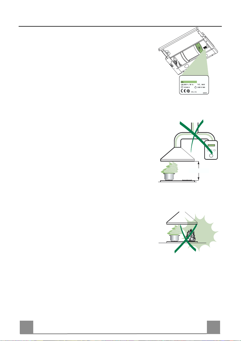
• The minimum safety distance between the cooker top and the extrac tor hood is 650 mm.
• Check that the mains voltage corresponds to that indicated on the
rating plate fixed to the inside of the hood.
• For Class I applianc es, c heck t hat th e domes tic po wer suppl y gua rantees adequate earthing.
Connect the extractor to the ex haust flue through a pi pe of minimum
diameter 120 mm. The route of the flue must be as short as possible.
• Do not connect the extractor hood to exhaust ducts carryi ng combustion fumes (boilers, fireplaces, etc.).
• If the extractor is used in conjuncti on with non-electrical appliances
(e.g. gas burning appliances), a suffici ent degree of aeration must be
guaranteed in the room in order to prevent the backflow of exhaust
gas. The kitchen must have an opening communicating directl y with
the open air in order to guarantee the entry of clean air.
USE
• The extractor hood has been designe d ex cl usi vely for domesti c us e to
eliminate kitchen smells.
• Neve r use the hood for pu rposes other than fo r which it has ben designed.
• Never leave high naked flames under the hood when it is in operation.
• Adjus t the flame intensity to direct it onto the bottom of the pan only,
making sure that it does not engulf the sides.
• Deep fat fryers must be continuously monitored during use: overheated oil can burst into flames.
• Do not flambè under the range hood; risk of fire
• The hood should not be used by chil dren or persons not inst ructed in
its correct use.
MAINTENANCE
• Switch off or unplug the appliance from the mains supply before carrying out any maintenance work.
• Clean and/or replace the Filters after the specified time period.
• Clean the hood using a damp cloth and a neutral liquid detergent.
650 mm min.
6
6
Page 7
EN
CHARACTERISTICS
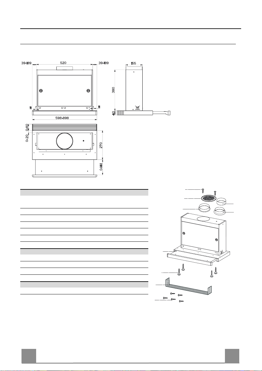
Dimensions
Components
Ref. Q.ty Product Components
1 1 Hood Body, complete with: Controls, Light, Blower,
8 1 Directional Air Outlet grille
9 1 Flange ø 150 mm
10a 1 Flange ø 120 mm
10b 1 Adapting ring ø 120-125 mm
20 1 Closing element
Ref. Q.ty Installation Components
12a 4 Screws 3,5 x 16
12e 2 Screws 2,9 x 12,7
12f 5 Screws 2,9 x 9,5
Q.ty Documentation
1 Instruction Manual
Filters
12f
12e
8
9
1
12a
20
10b
10a
7
7
Page 8
EN
INSTALLATION
1 2
3 5
Vr
6
7
8
4
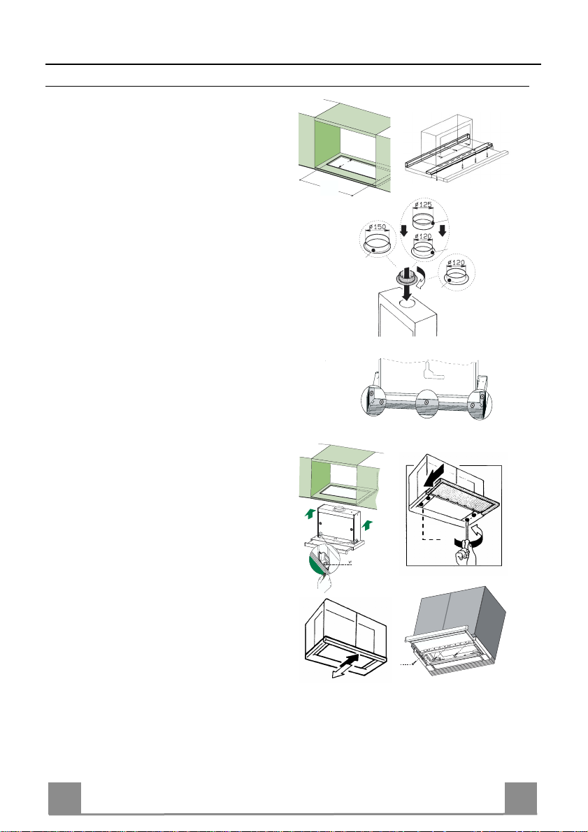
Drilling the Support surface and Fitting the Hood
• The Hood can be fitted directly on the
lower surface of the Wall Units (650 mm
min. above the Cooker Top) using the snapon Side Supports.
• Make an opening on the lower surface of
the Wall Unit, as indicated. (fig.1)
• Before carrying out the installation, the
wooden transportation protections screwed
on the visor and on the canopy body must
be removed. (fig.2)
• Choose the correct flange measure basing
on the air outlet diameter and insert it to the
upper air outlet opening. (fig.3)
• Screw the closing profile 20 onto the rear
part of the hood, using the screws 12f (2.9
x 9.5) provided. (fig.4)
• Open the sliding suction panel.
• Remove the metal grease filters one by one
after having disconnected the relative fastening elements.
• Close the sliding suction panel again.
• Insert the Hood until the snap-on side supports click into place. (fig.5)
• Open the sliding suction panel.
• Lock in position by tightening the screws
Vf from underneath the Hood. (fig.5)
• If necessary, adjust the whole filter holder
unit and proceed as follows:
• Loosen the four adjustment screws Vr
and close the sliding panel again. (fig.6)
• Move the entire filter holder unit until it
is properly aligned with the wall unit.
(fig.7)
• Keeping the hood canopy still, remove
the sliding panel and lock the adjustment
screws again. (fig.6)
• The hood can now be fastened to the
wall unit using the four screws 12a (3.5
x 16) provided. (fig.8)
• Replace the metal grease filters.
• Close the sliding suction panel again.
162
523
10b
10a
9
10a
12a
8
8
Page 9
EN
Connections
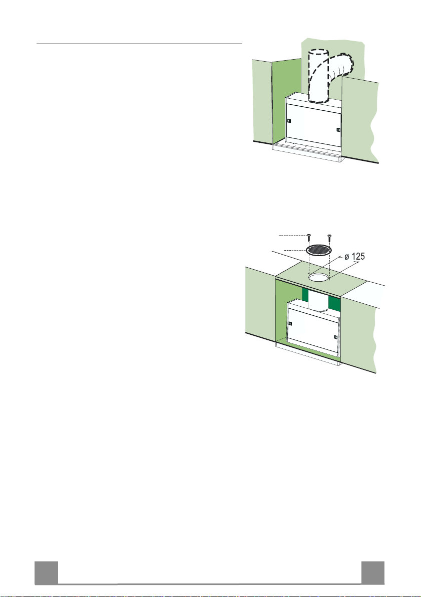
DUCTING VERSION AIR EXHAUST SYSTEM
When installing the hood in ducting version, a rigid or a
flexible pipe with the diameter corresponding to the
flange diameter is used i n order to conn ect the hood to
the air outlet piping.
• Fix the pipe with an adequate quantity of pipe
clamps (not supplied).
• Remove possible charcoal filters.
RECIRCULATION VERSION AIR OUTLET
• Cut a hole ø 125 mm in any shelf that may be positioned over the hood.
• Insert the flange 10a on the hood body outlet.
• Co nnect the flange to t he outlet on the sh elf over the
hood using a flexible or rigid pipe ø120 mm.
• Fix the pipe in position using sufficient pipe clamps
(not supplied).
• Fix the directional grille 8 on the recirculation air
outlet using the 2 screws 12e (2,9 x 12,7) provided.
• Ensure that the activated charcoal filters have been
inserted.
12e
8
ELECTRICAL CONNECTION
• Connect the hood to the mains through a two-pole switch having a contact gap of at least 3
mm..
9
9
Page 10
EN 110
USE
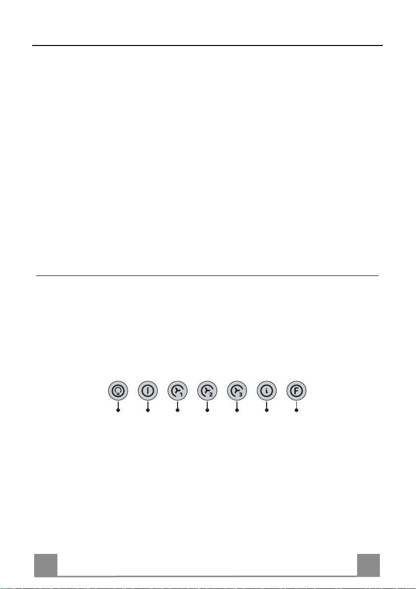
FUNCTION OF THE PULL-OUT SLIDING SUCTION PANEL
With the sliding panel kept closed is not possible to start up the motor of the hood, on the contrary is possible to engine and/or to switch off the lighting system. When the sliding panel is
pulled out the button pad is enabled, so that all functions are active and any functions that were
activated previously will be restored. Example: sliding panel pulled out : lights ON and motor
ON at speed T2; when the sliding pan el is pushed back in again all these functions are turn ed
off. When the sliding panel is pulled out again, the hood will automatically restore the previous state, that is to say light s ON, motor ON at speed T2. If intensive speed was turned on at
the time the sliding panel was closed, the hood will not return to intensive speed when the sliding panel is extracted, but to the speed set prior to that.
Control Panel
L T1 T2 T3 T4 T5 F
Page 11
EN 111
The hood can be switched on pushing directly onto the requested speed without firstly hav ing to select 0/1 button.
Touch
Basic functions
control
L
T1
T2
T3
Dual Function
When briefly pressed it switches the lighting system on
and off.
When pressed the motor is st opped, regar dless of the
speed it is set to.
When pressed the motor is set to the first s peed
By a brief pres sing the motor is set to the second speed. Touch control l it Second speed on
By pressing t he touch contr ol for approximately 2
seconds the Delay function is enabled, i.e delayed
shutdown of the appliance ensuring a co mplete
elimination of the residual odours. This function c an
be activated at OFF-posit ion and at 1°, 2° and
3°speeds. It can be stopped in advanc e by pressing
any of the touch controls (T) with the exception of
T3. The Delay function works according to the following scheme:
Indicator lights
Touch control
unlit
Touch control lit Motor on
Touch control
unlit
Flashing touch
control
Lights off
Motor off
Touch control lit
Delay function on
1°speed / OFF = 20 minuets
2°speed = 15 minutes
3°speed = 5 minutes
When pressed the motor is set to the third speed Touch control lit
T4
When pressed the motor is set to the intensive speed
T5
timed to 5 minutes. At the end of 5 minutes of intensive speed the hood starts again at the speed it was
set to previously. In case the hood is set to the inten-
Touch control lit
sive speed directly from OFF-state it will then start
from the first speed after 5 minutes of intensive
speed.
When pressed for 4 seconds it resets the filter alarm
F
signal indicated by flashing of the touc h control T1. This
procedure can be carried out only when t he motor is
stopped.
Touch control lit Metal grease filters
Flashing touch
control
saturation alarm. Metal
grease filters need to
be washed. The alarm
starts up after 100
working hours.
Charcoal odour fil ter
saturation alarm. Charcoal filter has to be
replaced and metal
grease filters washed.
The alarm star ts up
after 200 work ing
hours. (Activation;
check the paragraph
“Odour filter”)
Page 12

EN 112
MAINTENANCE
Grease filters
CLEANING OF THE METAL CASSETTE FILTERS
Alarm reset
• Stop the motor.
• Press the F -touch control for at least 4 seconds until the T1 -
touch control flashes.
Cleaning the filters
• Filters can be washed in the dish machine. They need to be
washed every 2 mont hs o r even more fr equ en tly in case of particularly intensive use of the hood.
• Pull out the sliding suction panel.
• Remove the filters one by one, after having disconnected the
relative fastening elements.
• Wash the filters, taking care not to bend them. Let them get dry
before refitting them. (The colour of the filter surface may
change throughout the time but this has no influence to the filter efficiency).
• When refitting the filters, make sure that the handle is visible
on the outside.
• Close the sliding suction panel.
Page 13

EN 113
Odour filter (Recirculation Version)
REPLACING THE CHARCO
AL ODOUR FILTER
This filter cannot be washed or regenerated, and must be replaced when the F touch control starts
to flash, or at least once ev e ry 4 months. The alarm is only trigge re d w he n the m otor is on.
Enabling/Disabling the alarm signal
• In Recirculation Version Hoods, the Filter saturation Alarm must be enabled at the time of
installation or later.
• Switch off the lights and the motor.
• Disconnect the mains power supply to the hood by removing the motor unit power supply
cable connector, switching off the power supply at the Mains or turning the Main switch off.
• Restore the connection, pressing and holding T2.
• Release the touch control, touch controls L, T2 and F will light up normally.
• Within 3 seconds press the touch control F until the key itself flashes to confirm as follows:
• 2 flashes – Charcoal odour Filter saturation Alarm ENABLED
• 1 flash - Charcoal odour Filter saturation Alarm DISABLED
Reset the alarm signal
• Stop the motor.
• P ress the touch control F for at least 4 seconds, until the touch
control T1 flashes.
Replace the Filter
• Pull out the sliding suction panel.
• Remove the metal grease filters.
• Remove the saturated ch arcoal filter, t urning the fast eners provided.
• Fit the new filter and fasten it its correct position.
• Put the metal grease filters in their seats.
• Close the sliding suction panel.
Lighting
LIGHT REPLACEMENT
20 W Halogen lamp.
• Remove the metal terminals fixing the metal panel.
• Slide the metal panel out of one of the fastening clips. Lower
the unfastened part of the panel slightly, so that it can be completely removed.
• Extract the lamp from the Support.
• Replace with another of the same type, making sure that the
two pins are properly inserted in the lamp holder socket holes
• Replace the metal p anel in reverse order.
Page 14

FR 114
CONSEILS ET SUGGESTIONS
INSTALLATION
• Le fabricant d écline toute responsabilité en cas de dommage dû à
une installation non correcte ou non conforme aux règles de l’art.
• La di stance minimale de sécurité entre le plan de cuisson et l a hotte
doit être de 650 mm au moins.
• Vérifier que la tensi on du sec teu r c or respond à l a val eur qui fi gu re s ur
la plaquette apposée à l’intérieur de la hotte.
• Pour les Appareils appartenant à la I
mise à la terre de l’installation électrique domestique ait été effectuée
conformément aux normes en vigueur.
• Connecter la hotte à la sortie d’air aspiré à l’aide d’une tuyauterie
d’un diamètre égal ou supérieur à 120 mm. Le parcours de la
tuyauterie doit être le plus court possible.
• Eviter de connecter la hotte à des conduites d’évacuation de fumées
issues d’une combustion tel que (Chaudière, cheminée, etc…).
• Si vous utilisez des appareils qui ne fonctionnent pas à l’électricité
dans la pièce ou est installée la hotte (par exemple: des appareils
fonctionnant au gaz), vous devez prévoir une aération suffisante du
milieu. Si la cuisine en est dépou rvue, pratiquez une ouverture qui
communique avec l’extérieur pour garantir l’infiltration de l’air pur.
UTILISATION
• La hotte a é té conçue exclusivement pour l’usage domestique, dans
le but d’éliminer les odeurs de la cuisine.
• Ne jamais utiliser abusivement la hotte.
• Ne pas lai sser les flammes libres à forte intensité quand la hotte es t
en service.
• Toujours régler les flammes de manière à éviter toute sortie latérale
de ces dernières par rapport au fond des marmites.
• Contrôler les friteuses lors de l’utilisation car l’huile surchauffée
pourrait s’enflammer.
• Ne pas prépa rer d’aliments flambés s ous la hotte de cuisine : risque
d’incendie
• La hotte ne doit pas être utilisée par des enfants ou des per sonnes ne
pouvant pas assurer une utilisation correcte.
ENTRETIEN
• Avant de procéder à toute opération d’entretien, retirer la hotte en
retirant la fiche ou en actionnant l’interrupteur général.
• Effectuer un entretien scrupuleux et en temps dû des F iltres, à la cadence conseillée.
• Pour le nettoyage des surfaces de la hotte, il suffit d’utiliser un chiffon
humide et détersif liquide neutre.
ère
Classe, veiller à ce que la
650 mm min.
Page 15

FR 115
CARACTERISTIQUES
Encombrement
Composants
Réf. Q.té Composants de Produit
1 1 Corps Hotte équipé de: Command es, Lumi ère, Groupe
8 1 Grille orientée Sortie de l’Air
9 1 Flasque ø 150 mm
10a 1 Flasque ø 120 mm
10b 1 Anneau de raccord Ø 120 - 125 mm
20 1 Profil fermeture
Réf. Q.té Composants pour l ’installation
12a 4 Vis 3,5 x 16
12e 2 Vis 2,9 x 12,7
12f 5 Vis 2,9 x 9,5
Q.té Documentation
1 Manuel d’instructions
Ventilateur, Filtres
12f
12e
8
9
1
12a
20
10b
10a
Page 16

FR 116
INSTALLATION
1 2
3 5
Vr
6
7
8
4
Perçage du Plan de support et Montage de la Hotte
• Il est possible d’installer la Hotte directement
sur le plan inférieur des Armoires murales (650
mm. min. par rapport aux Plaques de Cuisson), à
l’aide des Supports latéraux par encliquetage.
• Percer une ouverture (emboîtage) sur le plan
inférieur de l’Armoire murale, comme indiqué.
(fig.1)
• Avant de procéder au montage de la hotte, il
faut enlever les protections transport en bois vissées sur la partie inférieure et sur la carrosserie
de la hotte. (fig.2)
• Selon la base du diamètre de sortie de l’air choisi, insérer la flasque correcte dans le t rou supérieur de sortie de l’air. (fig.3)
• Visser le profil de fermeture 20 sur la partie
arrière de la hotte, en utilisant les vis 12f (2,9 x
9,5) fournies avec l’appareil. (fig.4)
• Sortir le chariot aspirant.
• Retirer les Filtres Anti-graisse l’un après l’autre,
en intervenant sur les crochets spécialement
prévus.
• Fermer le chario t aspirant.
• Insérer la Hotte jusqu’à accrocher les Supp orts
latéraux par encliquetage. (fig.5)
• Sortir le chariot aspirant.
• Bloquer définitivement la pièce, en serrant les
Vis Vf depuis le dessous de la Hotte. (fig.5)
• Si nécessaire, effectuer des ajustements du corps
porte-filtres tout entier, puis suivre les instructions suivantes:
• Desserrer les quatre vis de réglage Vr et re-
fermer le chariot. (fig.6)
• Déplacer le corps porte-filtres tout en tier, jus-
qu’à obtenir l’alignement souhaité de l’armoire murale. (fig.7)
• Toujours en maintenant bloqué le corps de la
hotte, sortir le chariot et bloquer à nouveau les
vis de réglage. (fig.6)
• Maintenant il est possible de fixer définitive-
ment la hotte contre l’armoire murale en utilisant les quatre vis 12a (3,5 x 16) fournies
avec l’appareil. (fig.8)
• Remonter les Filtres anti-graisse.
• Sortir le chariot aspirant
162
523
10b
10a
9
10a
12a
Page 17

FR 117
Branchements
SORTIE AIR VERSION ASPIRANTE
En cas d’installation en version aspirante, brancher la
hotte à la tuyauterie de sortie utilisant un tube rigide ou
flexible avec le même diamètre de la flasque précédemment installée.
• Fixer le tube par des colliers appropriés. Le matériau
nécessaire n’est pas fourni.
• Retirer les éventuels filtres anti-odeur au charbon
actif.
SORTIE AIR VERSION FILTRANTE
• Percer un trou de ø 125 mm. sur l’éventuelle Tablette
qui se trouve au-dessus de la Hotte.
• Insérer le flasque 10a sur la sortie du corps de la
hotte.
• Connecter la Flasque au trou de sortie sur la Tablette
qui se trouve au-dessus de la Hotte, au moyen d’un
tuyau rigide ou flexible de ø120 mm.
• Fixer le tube par des colliers appropriés. Le matériau
nécessaire n’est pas fourni.
• Fixer la Grille orientée 8 sur la sortie de l’air recyclé
à l’aide de 2 Vis 12e (2,9 x 12,7) fournies avec l’ ap-
pareil.
• S’assurer de la présence des filtres anti-odeur au
charbon actif.
12e
8
BRANCHEMENT ELECTRIQUE
• Brancher la ho tte sur le secteur en interposan t un interrupteur bipolaire avec ou verture des
contacts d’au moins 3 mm.
Page 18

FR 118
UTILISATION
FONCTION DU CHARIOT ASPIRANT ESCAMOTABLE
Quand le chariot est fermé, il n’est pas possible de mettre en marche le moteur de la hotte,
mais il est possibl e d’allumer et d’étei ndre l’éclairage. Quan d le chariot est o uvert, toutes les
touches s’activent ainsi que les fonctions ; de plus les fonctions activées au préalable reprennent leur état initial. Exemple : chariot ouvert : lumières allumées (ON) et moteur en marche
(ON) à la vitesse T2 ; si on referme le chariot, toutes les fonctions s’éteignent. Si par la suite
on ouvre à nouveau le chariot, la hotte reprend son état initial, c’est-à-dire lumières allumées
(ON) et moteur en marche à la vitesse T2. En cas de fonctionnement à la vitesse intensive à la
fermeture du chariot, quand celui-ci est ouvert à nouveau, la hotte fonctionnera à la vitesse réglée avant la vitesse intensive.
Tableau des commandes
L T1 T2 T3 T4 T5 F
Page 19

FR 119
Il est possible de mettre la hotte en marche directement à la vitesse désirée, en appuyant sur la touche correspondante sans passer par la touche 0 /1 moteur.
Touche
L
T1
T2
T3
Fonction base
Double fonction
Appuyer brièvement sur cette touche pour allumer et
éteindre les lumières.
Éteint le moteur fonctionnant à n’i mporte quelle vi tesse
Fait fonctionner le moteur en premièr e vitesse Voyant allumé
Appuyer brièvement pour faire fonctionner le moteur
en deuxième vitesse
Appuyer sur cette touche pendant e nv . 2 secondes pour déclencher la fonction “
à-d. l’arrêt retardé de l’appareil. Idéale pour éliminer complètement les ode urs résiduelles. Peut
être activée depuis la position « Arrêt » ou les vitesses 1,2,3 ; pour désactiver cette fonction, il
suffit d’appuyer sur n’importe quelle touche
sauf la T3. Le Retard prend effet selon les modalités suiva n tes:
1° vitesse / arrêt (OFF) = 20 minutes
2° vitesse = 15 minutes
Retard”, c-
Témoins lumineux
Voyant allumé
Voyant allumé
Voyant éteint
Voyant allumé
Voyant clignotant
(T),
Lumières allumées
Moteur actif
Moteur inactif
Deuxième vitesse active
Fonction Retard
Active
3°vitesse = 5 minutes
Fait fonctionner le moteur en troisi ème vitesse
T4
Fait fonctionner le moteur en vitess e intensive pend ant 5
T5
minutes. Après 5 minut es, l’appareil retourne à la vitesse
réglée au préalable. Si la mise en marche est effectuée
quand l’appareil est éteint, après 5 minutes le système
retourne à la première vitesse.
Appuyer sur cette touche pendant 4 secondes pour acquit-
F
ter le signal d’alarme des filtres, le témoi n l umineux T1
clignotera. Cette procédure peut être effectuée s eulement
quand le moteur ét eint.
Voyant allumé
Voyant allumé Signale l’alarme de saturation
Voyant clignotant
Voyant allumé
des filtres à graisse métalliques et l’exigenc e de les
laver. L’alarme se d éclenche
après 100 heures de fonctionnement effectif de la
hotte.
Quand il est activé, il signale
l’alarme de saturation du
Filtre anti-odeur au charbon
actif, qui doit être remplacé ;
les filtres à graisse métalliques doivent égal ement être
lavés. L’alarme in diquant la
saturation des Fil t res Antiodeur au charbon a ctif se
déclenche après 200 de
fonctionnement ef fectif de la
Hotte. (Pour la mise en marche voir le par. Filtr e anti-
odeur)
Page 20

FR 220
ENTRETIEN
Filtres à graisse
NETTOYAGE FILTRES A GRAISSE METALLIQUES
Acquittement du signal d’alarme
• Éteindre le Moteur d’aspiration.
• Appuyer sur la touche F pendant au moins 4 secondes, jusqu’à
ce que le voyant T1 clignote pour confirmer la mise en marche.
Nettoyage des filtres
• Ils sont lavables même en lave-vaisselle et doivent être lavés
environ tous les 2 mois ou plus souvent, en cas d’utilisation
particulièrement intensive.
• Ouvrir le chariot aspirant.
• Retirer les filtres un à un en agissant sur les crochets.
• Laver les filtres en évitant de les plier, et les faire sécher avant
de les remonter. (Tout change me nt d e cou leu r sur l a surface du
filtre, susceptible de se produire avec le temps, ne nuit en rien
à l’efficacité de ce dernier.)
• Remonter les filtres en faisant attention de tenir la poignée vers
la partie externe visible.
• Fermer le chario t aspirant.
Page 21

FR 221
Filtre anti-odeur (Version Filtrante)
Il ne peut être ni lavé ni récupéré, il faut le changer quand la touche F clignote ou au moins
tous les 4 mois. L’alarme fonctionne seulement quand le Moteur d’aspiration est en marche
Activation/Désa cti vation du signal d’alarme
• Pour les Hottes en Version Filtrante, l’alarme indiquant la saturation des Filtres doit être activée au moment de l’installation ou ultérieurement.
• Éteindre les lumières et le Moteur d’aspiration.
• Débrancher la Hotte en retirant la prise du groupe moteur ou en éteignant l’Interrupteur bipolaire de la hotte ou du réseau électrique.
• Rétablir le branchement en appuyant sur la touche T2.
• Relâcher la touche, les touches L, T2 et F s’allument sans clignoter.
• Dans les 3 secondes qui suivent, appuyer sur la touche F jusqu’à ce qu’elle clignote pour
confirmer la mise en marche :
• Le voyant clignote deux fois : MISE EN MARCHE alarme saturatio n Filtre anti-odeur au
Charbon
• Le voyant clignote une fois : EXTINCTION alarme saturation Filtre anti-odeur au Char-
bon
REMPLACEMENT DU FILTRE AN TI-OD EUR AU C HARB ON A C TIF
Acquittement du signal d’alarme
• Éteindre le Moteur d’aspiration.
• Appuyer sur la touche F pendant au moins 4 secondes, jusqu’à
ce que le voyant T1 clignote pour confirmer la mise en marche.
Remplacement du Filtre
• Ouvrir le chariot aspirant.
• Retirer les Filtres à graisse métalliques.
• Retirer le Filtre anti-odeur au Charbon actif saturé en agissant
sur les crochets.
• Mettre le nouveau Filtre en l’accrochant bien en place.
• Remonter les Filtres à graisse métalliques.
• Refermer le chariot aspirant.
Eclairage
REMPLACEMENT LAMPES
Lampes fluorescentes de 9 W.
• Retirer les étaux métalliques qui fixent le support métallique.
• Faire glisser le support métallique sur un côté jusqu’à libérer
l’extrémité opposée. Abaisser légèrement l’extrémité libre et le
faire glisser jusqu’à le libérer totalement.
• Remplacer la lampe par une nouvelle avec les mêmes c aractéristiques.
• Remonter le support métallique dans la séquence inverse.
Page 22

DE 222
EMPFEHLUNGEN UND HINWEISE
MONTAGE
• Der Herstell er haftet nicht für Schäden, die auf ein e fehlerhafte und
unsachgemäße Montage zurückzuführen sind.
• Der minimale Sicherheitsabstand zwischen Kochmulde und Haube
muss 650 mm betragen.
• Prüfen, ob die Netzspannung mit dem Wert au f dem im Haubeninneren angebrachten Schild übereinstimmt.
• Bei Geräten d er Klasse I ist sicherz ustellen, dass die elektri sche Anlage des Wohnhauses über eine vorschriftsmäßige Erdung verfügt.
• Das Anschlussrohr der Haube zur Luftaustrittsöffnung muss einen
Durchmesser von 120 mm oder darüber aufweisen. Der Rohrverl auf
muss so kurz wie möglich sein.
• Die Haube darf an keine Entlüftungs schächte anges chloss en werden,
in die Verbrennungsgase (Heizkessel, Kamine usw.) geleitet werden.
• Werden im Raum außer der Dunsta bzugshaube andere, nicht elektrisch betriebene (z.B. gasbetri ebene) Geräte verwendet, muss für eine ausreichende Belüftung gesorgt werden. Sollte die Küche diesbezüglich nicht entsprechen, ist an ein er Aussenwand eine Öffn ung anzubringen, die Frischluftzufuhr gewährleistet.
BEDIENUNG
• Die Dunstabzugshaube ist ausschließlich zum Einsatz im privaten
Haushalt und zur Beseitigung von Küchengerüchen vorgesehen.
• Unsachgemäßer Einsatz der Haube ist zu unterlassen.
• Große Flammen bei eingeschalteter Haube niemals unbedeckt lassen.
• Die Intensivität der Flamme i st so zu reguliere n, dass s ie den Topfboden nicht überragt.
• Frittiergeräte müssen während des Gebrauchs stets beaufsichtigt
werden: überhitztes Öl kann sich entzünden.
• Keine flambierten Speisen unter der Abzugshaube zubereiten:
Brandgefahr.
• Die Dunstabzugshaube da rf vo n Kindern oder Pe rsonen, die hins ichtlich der Bedienung nicht unterwi esen wurden, keinesfalls verwendet
werden.
WARTUNG
• Bevor Wa rtungsarbeiten du rchgeführt werden, mus s die Stromzufuh r
zur Haube unterbrochen werden, indem der Stecker gezogen oder
der Hauptschalter abgeschaltet wird.
• Bei der F ilterwartung müssen die vom Hersteller empfohlenen Zeiträume zum Austauschen der Filter genauestens eingehalten werden.
• Zur Reinigung der Haubenfl ächen Wir empfehlen ein feuchtes Tuch
und ein mildes Flüssigreinigungsmittel.
650 mm min.
Page 23

DE 223
CHARAKTERISTIKEN
Platzbedarf
Komponenten
Pos. St. Produktkomponenten
1 1 Haubenkörper mit Schaltern, Beleuchtung, Gebläse-
8 1 Luftleitgitter Luftaustritt
9 1 Flansch ø 150 mm
10a 1 Flansch ø 120 mm
10b 1 Vergrößerun gsring Ø 120-150 mm
20 1 Abdeckprofil
Pos. St. Montagekomponenten
12a 4 Schrauben 3,5 x 16
12e 2 Schrauben 2,9 x 12,7
12e 5 Schrauben 2,9 x 9,5
St. Dokumentation
1 Bedienungsanleitung
gruppe, Filter
12f
12e
8
9
1
12a
20
10b
10a
Page 24

DE 224
MONTAGE
1 2
3 5
Vr
6
7
8
4
Bohren der Trägerplatte und Montage der Dunstabzugshaube
• Die Haube kann direkt an der Unterseite der
Hängeschränke (mindestens 650 mm von der
Kochmulde entfernt) mit seitlichen Schnapphalterungen fixiert werden.
• An der Unterseite des Hängeschranks, wie in
der Abbildung gezeigt, eine Öffnung anbringen.
(Abb.1)
• Vor dem Einbau müssen die als Transportsicherung auf dem Schirm geschraubten Holzleisten
abgenommen werden. (Abb.2)
• Je nach Durchmesser des gewählten Luftaustritts den passenden Flansch in die obere Abluftöffnung einsetzen. (Abb.3)
• Das Abschlussprofil 20 an der Rückseite der
Haube mit den beiliegenden Schrauben 12f
(2,9x9,5) fixieren. (Abb.4)
• Den herausziehbaren Wrasenleitschirm öffnen.
• Die Fettfilter nacheinander entnehmen, indem
die entsprechenden Haltevorrichtungen gelöst
werden.
• Den herausziehbaren Wrasenleitschirm wieder
schließen.
• Die Haube einschieben, bis die seitlichen Halterungen einschnappen. (Abb.5)
• Den herausziehbaren Wrasenleitschirm öffnen.
• Die Haube von unten her mit den Schrauben Vf
fixieren. (Abb.5)
• Falls erforderlichk, das unter Teil wie nach stehend beschrieben ausr ichte n:
• Die vier Einstellschrauben Vr lockern und
den Wrasenleitschirm wieder schließen.
(Abb.6)
• Den gesamten unteren Korpus verschieben,
bis er auf den Oberschrank ausgerichtet ist.
(Abb.7)
• Den Haubenkörper festhalten, den Wrasen-
leitschirms öffnen und die Einstellschrauben
festziehen. (Abb.6)
• Nun kann die Haube am Oberschrank mit den
vier beiliegenden Schrauben 12a (3,5 x 16)
fixiert werden. (Abb.8)
• Die Fettfilter wieder montieren.
• Den herausziehbaren Wrasenleitschirm wieder
schließen.
162
523
10b
10a
9
10a
12a
Page 25

DE 225
Anschlüsse
ANSCHLUSS BEI ABLUFTBETRIEB
Für die Installation der Haube im Abluftbetrieb mit Hilfe eines Rohres oder Schlauches vom selben Durchmesser wie der zuvor installierte Flansch (ø 150mm, ø
125 mm oder ø 120 mm) am Gebläseaustrittsstutzen
anschließen.
• Das Roh r mit geeigneten Rohrschellen fixieren. Das
hierzu erforderliche Material wird nicht mitgeliefert.
• Eventuell vorhandene Aktivkohlefilter entnehmen.
ANSCHLUSS BEI UMLUFTBETRIEB
• In das eventuell über der Haube vorhandene Bord ein
Loch ø 125 mm bohren.
• Den Flansch 10a am Haubenaustritt anbringen.
• Den Flansch beim Luftaustritt oberhalb der Haube
mit Rohr oder Schlauch ø120 mm verbinden.
• Das Rohr mit geeigneten Ro hrschellen fixieren. Das
hierzu erforderliche Material wird nicht mitgeliefert.
• Das Luftleitgitter 8 mit Hilfe von 2 der mitgelieferten
Schrauben 12e (2,9 x 12,7) auf dem Hängeschrank.
• Sicherstellen, dass der Aktivkohlefilter eingesetzt ist
12e
8
ELEKTROANSCHLUSS
• Bei Anschluss der Haube an das Stromnetz muss ein zweipoliger Schalter mit einem Öffnungsweg von mindestens 3 mm zwischengeschaltet werden.
Page 26

DE 226
BEDIENUNG
ittens:
FUNKTION DES AUSZIEHBAREN ANSAUGSCHL IT T ENS
Bei geschlossenem Ansaugschlittens kann der Motor nicht betätigt werden. Dagegen ist es
moeglich, die Beleuchtung ein- oder auszuschalten. Wird der Ansaugschlittens herausgezogen,
erfolgt die Freigabe des Bedi enfeldes und alle seine Funktionen werden aktiviert; die zuvo r
eingestellten Funktionen sind erneut aktiviert. Beispiel: herausgezogener Ansaugschl
Beleuchtung ON und Motor ON auf T2; bei Schließen des Ansaugschlittens werden alle Funktionen deaktiviert. Wird der Ansaugschlittens in der Folge wieder geöffnet, werden die zuvor
gültigen Bedingungen wieder hergestellt, d.h. Beleuchtung ON Motor ON mit Gebläsestufe
T2. War beim Schließen des Wrasenleitschirms die Intensivstufe eingestellt, schaltet sich beim
Öffnen des Ansaugschlittens nicht die Intensivstufe ein, sondern die zuvor gewählte Gebläsestufe.
Bedienfeld
L T1 T2 T3 T4 T5 F
Page 27

DE 227
Die Haube kann direkt auf die gewünschte Stufe eingeschaltet werden ohne daß man vorher auf die Gebläsetaste
0/1 drückt.
Grundfunktion
Taste
Doppelfunktion
Ein kurzer Tas tendruck schaltet die Bel euchtungsanlage
L
ein und aus.
Schaltet den Motor unabhängig von der Gebläsestuf e ab
T1
Aktiviert den Motor mit der ersten Gebläsestufe
T2
Bei kurzem Drüc ken dieser T aste wird der Mot or mit der
T3
zweiten Gebläsestufe aktiviert
Wird die Taste cirka 2 Sekun den lang gedr ückt, aktiviert sich die Funktion Delay, d.h. die verzögerte A b-
schaltung des Gerätes. Eignet sich zur kompletten
Beseitigung v on Restgerüchen. Kann in der Positio n
OFF und den Gebläsestufen 1, 2, 3 aktivi ert werden;
kann vorzeit ig durch Drück en jeder beliebigen Tast e
(T) (mit Ausnahme der Taste T3) deaktiviert werden.
Die Delay-Funktion erfolgt nach nachstehendem
Zeitplan:
1. Stufe / OFF = 20 Minuten
2. Stufe = 15 Minuten
3. Stufe = 5 Minuten
Aktiviert den Motor mit der dr itten Gebläsestufe
T4
Aktiviert den Motor mit der 5 Minuten dauernden Intensiv-
T5
stufe. Nach Ablauf der 5 Min uten läuft das Gerät wieder
mit der zuvor eingestellten Sauggeschwindigkeit. Wird
diese Funktion bei ab ges c hal tetem Gerät aktiv ier t, wird
nach Ablauf der 5 Minute n auf die ers te Gebläsestufe
übergegangen.
Wird die Taste 4 Sekunden lang gedrückt , erfolgt die
F
Rückstellung des Filteralarms, der durch Blinken der Taste T1 angezeigt wird. Dieses Ver fahren kann nur bei abgeschaltete m Motor durchg eführt werden.
Taste erloschen
Taste leuchtet auf
Taste erloschen
Taste leuchtet auf
Taste blinkt Delay-Funkt ion ak t iv ier t
Taste leuchtet auf
Taste blinkt Sättigungsanzeige der Aktiv-
Leuchtsignale
Beleuchtung abgeschalt et
Motor aktiviert
Motor deaktivi ert
Taste leuchtet auf
Zweite Gebläsestufe aktiviert
Taste leuchtet auf
Taste leuchtet auf
Sättigungsanzeige der M etallfettfilter, die gewaschen
werden müssen. Der Alarm
erfolgt nach 100 effektiven
Arbeitsstund en der Ha ube.
kohle-Geruchsfilter, f alls
diese aktiv iert wurde; die
Filter sind auszutauschen;
die Metallfettfilter müssen
ebenfalls gewaschen werden. Die Sättigungsanzeige
des Aktivkohle-Geruchsf ilters
erfolgt nach 200 effektiven
Arbeitsstund en der Ha ube.
(Aktivierung siehe Abschn.
Geruchsfilter)
Page 28

DE 228
WARTUNG
Fettfilter
REINIGUNG DER SELBSTTRAGENDEN METALLFETTFILTER
Rückstellen der Sättigungs anzeige
• Den Gebläsemotor abschalten.
• Die Taste F mindestens 4 Sekunden lang drücken, bis die Taste
T1 als Bestätigung zu blinken beginnt.
Filterreinigung
• Die Filter können auch im Geschirrspüler gereinigt werden und
sollten cirka alle 2 Monate - bzw. bei sehr intensivem Einsatz
auch häufiger - gereinigt werden.
• Den Ansaugschlitten herausziehen.
• Die entsprechenden Haken lösen und die Filter einzeln herausnehmen.
• Die Filter reinigen und vor dem Wiedereinsetzen trocknen lassen, dabei nicht knicken. (Eine eventuelle Verfärbung der Filteroberfläche, zu der es im Laufe der Zeit kommen kann, beeinträchtigt die Wirksamkeit des Filters keinesfalls.)
• Die Filter wieder einsetzen, dabei darauf achten, dass der Griff
nach außen hin sichtbar ist.
• Den Ansaugschlitten wieder schließen.
Page 29

DE 229
Geruchsfilter (Umluftbetrieb)
AUSTAUSCHEN DES AKTI
VKOHLE
-
GERUCHSFILTER
Dieser Filter ist weder wasch- noch wiederverwendbar und ist auszutauschen, wenn die Taste
F blinkt oder zumindest alle 4 Monate. Die Sättigungsanzeige erfolgt nur, wenn der Gebläsemotor eingeschaltet ist.
Aktivierung/Deaktivierungder S ättigungsa nzeige
• Bei Hauben mit Umluftbetrieb erfolgt die Aktivierung der Sättigungsanzeige bei der Installation oder später.
• Die Beleuchtung und den Gebläsemotor abschalten.
• Die Haube vom Stromnetz trennen, indem der Verbinder des Speisekabels der Motorgruppe
gezogen oder der zwischengeschaltete zweipolige Schalter oder der Hauptschalter betätigt
wird.
• Den Anschluss wieder herstellen, während die Taste T2 gedrückt gehalten wird.
• Die Taste loslassen; die Tasten L, T2 und F leuchten pausenlos auf.
• Inne rhalb von 3 Sekunden die Taste F solange drücken, bis sie als Bestätigung zu blinken
beginnen:
• 2-maliges Blinken – Sättigungsanzeige Aktivkohle-Geruchsfilter AKTIVIERT
• 1-maliges Blinken – Sättigungsanzeige Aktivkohle-Geruchsfilter DEAKTIVIERT
Rückstellen der Sättigungs anzeige
• Den Gebläsemotor abschalten.
• Die Taste F mindestens 4 Sekunden lang drücken, bis die Taste
T1 als Bestätigung zu blinken beginnt
Filterwechsel
• Den Ansaugschlitten herausziehen.
• Die Metallfettfilter entfernen.
• Den gesättigten Aktivkohle-Geruchsfilter anhand der entsprechenden Anhakvorrichtungen demontieren.
• Den neuen Filter montieren, indem er in seinem Sitz eingehakt
wird.
• Die Metallfettfilter wieder montieren.
• Den Ansaugschlitten wieder schließen
Beleuchtung
AUSWECHSELN DER LAMPEN
Halogenlampe 20 W
• Die Metallverschlüsse die die Metallplatte fixieren, entfernen.
• Die Metallplatte auf eine Seite schieben, bis das andere Ende
freigegeben wird. Leicht senken und verschieben, bis die Metallplatte gänzlich entnommen werden kann.
• Die Lampe aus der Halt erung nehmen.
• Die Lampe durch eine gleichwertige ersetzen und bei der Remontage darauf achten, dass die beiden Steckerstifte vorschriftsmäßig in die Lampenfassung eingeführt werden
• Bei der Remontage der Metallplatte in umgekehrter Reihenfolge vorgehen.
Page 30

NL 330
ADVIEZEN EN SUGGESTIES
INSTALLATIE
• De fabrikant aanvaardt geen enkele aansprakelijkheid voor schade
die voortkomt uit onjuiste of niet overeenkomsti g de regels der kuns t
uitgevoerde installaties.
• De minimale veiligheids afstand tusse n de kookpl aat en de was emkap
bedraagt 650 mm.
• Controleer of de netspanning correspondeert met de spanning die
aangegeven is op het plaatje aan de binnenkant van de wasemkap.
• Voor apparaten van klasse I dient u zich ervan te verzeke ren dat het
elektriciteitsnet in uw huis over een goede aarding beschikt.
• Verbind de wasemkap met de luchtuitl aat door middel van een l eiding
met een diameter van 120 mm of groter. De leiding moet een zo kort
mogelijke route afleggen.
• Sluit de wasemkap niet aan op afvoerpijpen van rook die geproduceerd is door verbranding (verwarmingsketels, open haarden etc.).
• Als er in het vertrek zowel de wase mkap als apparaten die niet op
elektriciteit werken (bijvoorbeeld gasapparaten) worden gebruikt,
moet ervoor worden gezo rgd dat het vertrek voldoe nde geventileerd
wordt. Indien de keuken geen gat in de buitenmuur heeft om de aan voer van schone lucht te garanderen, dient dit gemaakt te worden.
GEBRUIK
• De wasemkap is uitsluitend ontworpen voor huishoudelijk gebruik,
voor het elimineren van kookgeur en. Gebruik de kap nooit op oneigenlijke wijze.
• Laat geen hoog brandende branders onbedekt onder de wasemkap
terwijl deze in werking is.
• Regel de vlammen altijd zo dat ze niet l angs de pannen omhoogkomen.
• Controleer fri tuurpannen tijdens het gebruik: de ov erverhitte olie zou
vlam kunnen vatten.
• Er mag niet onder de afzuigkap geflambeerd worden; brandgevaar
• De wasemkap mag niet gebruik t wor den door k inderen of doo r pe rsonen die niet in staat zijn de kap correct te gebruiken.
ONDERHOUD
• Al vorens onderhoudswerkzaamh eden uit te voeren, moet de wasemkap uitgeschakeld worden door de stekker ui t het s topcontac t te halen
of de hoofdschakelaar om te zetten.
• Voer het onderhoud van de filters altijd tijdig en nauwgezet uit,volgens
de aanbevolen intervallen.
• Om de oppervlakken van de k ap schoon te maken is het voldoende
een vochtige doek en een neutraal reinigingsmiddel te gebruiken.
650 mm min.
Page 31

NL 331
EIGENSCHAPPEN
Buitenafmetingen
Onderdelen
Ref. Productonderdelen
1 1 Wasemkap compleet met:Bedieningen, Licht, Ventilat-
8 1 Richtingrooster luchtuitlaat
9 1 Flens ø 150 mm
10a 1 Flens ø 120 mm
10b 1 Aanpassingsring Ø 120-125 mm
20 1 Sluitprofiel
Ref. Installatieonderdelen
12a 4 Schroeven 3,5 x 16
12e 2 Schroeven 2,9 x 12,7
12f 5 Schroeven 2,9 x 9,5
Documentatie
1 Gebruiksaanwijzing
orgroep, Filters
12f
12e
8
9
1
12a
20
10b
10a
Page 32

NL 332
INSTALLATIE
1 2
3 5
Vr
6
7
8
4
Boren van gaten in draagvlak en montage wasemkap
• De wasemkap kan rechtstreeks op het onderste
vlak van het keukenkastje (min. 650 mm van
de kookplaat) worden geïnstalleerd met behulp
van de zijsteunen met klikbevestiging.
• Ga voor de inbouw van de wasemkap op het
onderste vlak van het keukenkastje, als volgt te
werk. (fig.1)
• Voor alleer verder te gaan met de montage, is
het noodzakelijk de houten beschreming voor
het vervoer, te verwijderen. (fig.2)
• Afhankelijk van de gekozen diameter van de
luchtuitlaat, moet U de juiste flens plaatsen in
het bovenste gat voor de luchtafvoer. (fig.3)
• Schroef het sluitprofiel 20 aan de achterkant
van de wasemkap vast met behulp van de bijgeleverde schroeven 12f (2,9 x 9,5). (fig.4)
• Trek de rolletjes met de zuiggroep naar voren.
• Verwijder de vetfilters één voor één door de
haken los te maken.
• Sluit opnieuw de zuiggroep.
• Plaats de wasemkap totdat de zijsteunen met
klikbevestiging vastgehaakt zijn. (fig.5)
• Trek de rolletjes met de zuiggroep naar voren.
• Blokkeer de wasemkap definitief door de
schroeven Vf vanaf de onderkant van de wasemkap aan te draaien. (fig.5)
• Voer eventueel enige afstellingen uit in de behuizing van de filterhouder en ga daarvoor als
volgt te werk:
• Draai de vier stelschroeven Vr los en sluit
het zuiggroep weer. (fig.6)
• Verplaats de hele behuizing van de filter-
houder totdat de gewenste uitlijning van het
keukenkastje is verkregen. (fig.7)
• Houd de behuizing van de wasemkap stil en
verwijder het zuiggroep. Blokkeer vervolgens de stelschroeven weer. (fig.6)
• Nu kan de wasemkap definitief aan het keu-
kenkastje worden bevestigd met behulp van
de vier bijgeleverde schroeven 12a(3,5 x
16). (fig.8)
• Monteer de vetfilters weer.
• Sluit opnieuw de zuiggroep.
162
523
10b
10a
9
10a
12a
Page 33

NL 333
Aansluitingen
LUCHTUITLAAT AFZUIGVERSIE
In het geval van installatie in afzuigversie, moet u de
wasemkap met de uitlaatleiding verbinden door middel
van een starre of buigzame l eiding die dezelfde d iameter heeft als de reeds geïnstalleerde flen s.
• Zet de leiding vast met geschikte leidingklemmen.
Het benodigde materiaal wordt niet bij de wasemkap
bijgeleverd.
• Verwijder de eventuele geurfilters met actieve koolstof.
LUCHTUITLAAT FILTERVERSIE
• Boor een gat van ø 125 mm in de eventuele plank
boven de kap.
• Breng de flens 10a op de uitlaat van de wasemkap
aan.
• Verbind de flens met de uitlaatopening op de plank
boven de kap met behulp van een starre of flexibele
leiding van ø1 20 mm.
• Zet de leiding vast met geschikte leidingklemmen.
Het benodigde materiaal wordt niet bij de wasemkap
geleverd.
• Bevestig het richtingsrooster 8 op de uitlaat van de
gerecirculeerde lucht met 2 van de bijgeleverde
schroeven 12e (2,9 x 12,7).
• Verzeker u ervan dat het geurfilter met actieve koolstof geïnstalleerd is.
12e
8
ELEKTRISCHE AANSLUITING
• Sluit de wasemkap aan op de netspanning met een tweepolige schakelaar ertussen met een
opening tussen de contacten van tenminste 3 mm.
Page 34

NL 334
GEBRUIK
DE WERKING VAN DE UITTREKBARE AFZUIGGROEP
Als de afzuiggroep niet ui tgetro kken is, kan d e afzui gkap n iet wor den aan gezet. De verl ich tin g
daarentegen kan wel aan- of ui tgeschakeld worden . Door de afzuiggro ep uit te trekken , wordt
het toetsenbord in werking gezet en worden alle functies van de wasemkap geactiveerd. De
afzuigkap herneemt bovendien ook de functies die tevoren werden ingesteld. Bijvoorbeeld:
met uitgetrokken afzuiggroep: verlichting AAN en motor AAN op T2; als U de afzuiggroep
sluit, worden alle functies ui tgeschakeld. Als U daarna de afzuiggroep opn ieuw uittrekt, herneemt de wasemkap de vori ge t oest and , en wel verlichting AAN en motor AAN op T2. Als op
het moment van het sluiten van de afzuiggroep de intensieve snelheid actief was, dan herneemt
de afzuigkap deze niet wanneer de groep nadien weer wordt uitgetrokken. Het toestel activeert
dan de daarvoor ingestelde snelheid.
Controle pannel
L T1 T2 T3 T4 T5 F
Page 35

NL 335
U kan de afzuigkap onmiddellijk aanzetten op de gewenste snelheid door op de betrekkelijke toets te drukken
zonder dat U eerst op de 0/1 toets drukt.
Basisfunctie Toets
Lichtsignalen
Dubbele functie
Als U even op deze toets drukt , schakelt U de verli-
L
chting aan of ui t.
Schakelt de motor uit van op el ke snelhei d
T1
Activeert de motor op de eerst e sn elh eid
T2
Als U even op deze toets drukt , activeert U d e motor
T3
op de tweede s nelheid
Door circa 2” op deze toets te drukken, wor dt de
Delay functi e of ook vertraagde uitsch akeling van
het toestel g eactiveerd. Zeer geschikt om restgeurtjes te v erwijderen. Deze functie kan zowel
geactiveerd worden vanuit de stand OFF als van
op snelheid 1, 2, 3 . De functi e kan voorti jdig worden afgebroken door op eender welke to ets (T) te
drukken, met uitzo nd eri n g van T3. De vertraagde
uitschakeling gebeurt volgens dit schema:
1° snelheid / OFF = 20 minuten
2° snelheid = 15 minuten
3° snelheid = 5 minuten
Activeert de motor op de der de snelheid Toets aan
T4
Activeert de motor geduren de 5 minuten op de inten-
T5
sieve snelheid. Na 5 minute n keert het toestel terug
naar de daarvoor ingestelde snelheid. Als deze func tie
wordt geacti veerd wanneer de afzuigkap uit staat,
keert het afzuigsysteem na 5 minuten terug naar de
eerste snelheid.
Als U circa 4 seconden op deze toets drukt, wordt het
F
alarm verzadiging filters hersteld, T1 knippert ter bevestiging. Dez e proc e dur e kan all e en uit v oer d wor den
als de motor is uitgeschakeld.
Toets
verlicht
Toets
verlicht
Toets uit Motor uit
Toets
aan
Toets
knippert
Toets
aan
Toets
aan
Verlichting aan
Motor aan
Toets aan
Tweede snel heid actief
Delay Functi e is geactiveerd
Toets aan
Signaleert het alarm verzadiging
metalen vetfilters, hetgeen wil
zeggen dat deze moeten worden
afgewassen.
Het alarm wordt geactiveerd na
100 effectieve bedrijfsuren van de
afzuigkap.
Signaleert, wanneer hij g eactiveerd wordt, het alarm Verzadiging Koolstof filter, het geen wil
zeggen dat de filter moet worden
vervangen. Ook de metalen vetfilters moeten worden afgewassen.
Het alarm Verzadiging Filt er met
actieve kools tof wordt ge activeerd
na 200 effectieve be dri jf sur e n van
de afzuigkap. (Activeri ng zie paragraaf Geurfilter)
Page 36

NL 336
ONDERHOUD
Metalen Vetfilters
SCHOONMAAK VAN DE ZELFDRAGEND E METALEN V ETFILTERS
Reset van het alarmsignaal
• Schakel de afzuigmotor uit.
• Druk gedurende 4 seconden op toets F, tot toets T1 knippert ter
bevestiging.
Schoonmaa k van de Fil te rs
• De filters zijn ook afwasbaar in de vaatwasmachine en moeten
elke 2 maanden gereinigd worden of zelfs vaker indien U de
afzuigkap zeer intensief gebruikt.
• Trek de zuiggroep naar voren.
• Verwijder de filters één voor één door aan de daarvoor bestemde haakjes te trekken.
• Was de filters zonder ze te vouwen en laat ze drogen alvorens
ze weer terug te plaatsen. (Na verloop van tijd is het mogelijk
dat de oppervlakte van de filter van kleur verandert, maar dit
benadeelt de efficiëntie van de filter helemaal niet.)
• Plaats de vetfilters terug en zorg ervoor dat de handgreep
zichtbaar blijft.
• Sluit opnieuw de zuiggroep.
Page 37

NL 337
Geurfilters met actieve koolstof (Filterversie)
Deze filter is niet afwasbaar en kan niet herb ruikt worden. De koolstoffilter moet vervangen
worden als toets F knippert of minstens eenmaal in de 4 maanden. Het alarmsignaal wordt alleen aangegeven als de zuigmotor actief is.
Activering/Desa c tivering van het alarmsignaal
• Bij wasemkappen met luchtcirculatie moet het alarmsignaal dat aangeeft dat de filters verzadigd zijn, geactiveerd worden op het moment van de installatie of daarna.
• Schakel de verlichting en de zuigmotor uit.
• Sluit de wasemkap van het elektriciteitsnet af door de connector van de voedingskabel uit de
motorgroep te verwijderen, of door de 2-polige schakelaar uit te schakelen die tussen de
netvoeding staat, ofwel door de hoofdschakelaar uit te schakelen.
• Sluit de wasemkap weer aan op het net door toets T2 ingedrukt te houden.
• Laat de toets los, de leds van de toetsen L, T2 en F branden nu voortdurend.
• Druk binnen 3 seconden op de toets F totdat de led gaat knipperen ter bevestiging:
• 2 maal knipperen – Alarm verzadiging geurfilter met actieve koolstof GEACTIVEERD
• 1 maal knipperen – Alarm verza diging geurfilter met actieve koolstof G E DE SACTIVEERD
VERVANGING VAN DE GEURFILTER MET ACTIEVE KOOLSTOF
Reset van het alarmsignaal
• Schakel de afzuigmotor uit.
• Druk gedurende 4 seconden op toets F, tot toets T1 knippert ter b evestiging.
Vervanging van de Filter
• Trek de zuiggroep naar voren.
• Verwijder de metalen vetfilters.
• Verwijd er de verzadigd e geurfilter met acti eve koolstof door de h aakjes los te maken.
• Monteer de nieuwe geurfilter en druk hem goed op zijn plaats vast.
• Monteer opnieuw de metalen vetfilters.
• Sluit opnieuw de zuiggroep.
Verlichting
VERVANGING VAN DE LAMPEN
Halogeenlamp van 20 W.
• Verwijder de metalen klemmen waarmee de metalen drager is
bevestigd.
• Schuif de metalen drager naar één kant tot het andere uiteinde
vrijkomt. Breng het vrije uiteinde enigszins omlaag en schuif
het opzij tot de metalen drager volledig vrijkomt.
• Vervang de lamp door een nieuwe lamp met dezelfde eigenschappen.
• Ga voor het terugplaatsen van de metalen drager in omgekeerde volgorde te werk.
Page 38

Page 39

Page 40

The symbol on the product or o n i ts pac kaging indicates that this pr o d uc t m ay n ot b e tr e ated as household waste. Ins tead it shall
be handed over to the appl icable col lection p oint for t he recycli ng of electr ical and el ectronic equipment . By ensurin g this product is
disposed of correctly, you will help prevent potential negative consequences for the environment and human health, which could otherwise be caused by inap propr iat e wast e ha ndl ing of this pro duc t. For mor e det ail ed inf ormati o n about recy cli ng of this pro duc t, ple ase
contact your local city office, your household waste disposal service or the shop where you purchased the product.
Le symbole sur le produit ou s on em bal la ge in diqu e que c e pro dui t ne peut ê tre tr aité c omm e déc he t mén ager. Il doi t plut ôt être
remis au point de ramassage concerné, se chargeant du recyclage du matériel électrique et électronique. En vous assurant que ce
produit est éli miné cor rectem ent, v ous fav orise z la prév entio n des cons équ ences né gativ es po ur l’env ironnem ent et l a sant é humaine
qui, sinon, serai e nt le résultat d’un traiteme nt inapproprié des déchets de ce produit. Pour obteni r pl us de dé tai ls sur le recyclage de ce
produit, veuillez prendre contact avec le bureau municipal de votre région, votre service d’élimination des déchets ménagers ou le
magasin où vous av ez acheté le produit.
Das Symbol auf dem Produk t oder s einer V erpac kung weist dar auf hi n, dass di eses Prod ukt ni cht als nor maler Haus halts abfall
zu behandeln is t, so nder n an ei nem Sam mel pu nkt f ür das Rec ycl ing v on elek tri sc hen und elek tr onisc he n G eräte n abg egeb en w er den
muss. Durch Ihren Beitrag zum korr ek te n Entsorgen dieses Prod uk ts s chützen Sie die Umwelt und die Gesundheit Ihrer M i tm enschen.
Umwelt und Ges undheit werden durc h falsches Entsorge n gefährdet. Weitere Informationen über das Recycling dieses Pr odukts
erhalten Sie von Ihrem Rathaus, Ihrer Müllabfuhr oder dem Geschäft, in dem Sie das Produkt gekauft haben.
Het symbool op het product of op d e verpakki ng wijst erop d at dit product ni et als huis houdafval m ag worden beha ndeld. Het
moet echter naar een plaats worden gebracht waar elektrische en elektronische apparatuur wordt gerecycled. Als u ervoor zorgt dat dit
product op de correcte manier wordt verwijderd, voorkomt u mogelijk voor mens en milieu negatieve gevolgen die zich zouden kunnen
voordoen in geval va n verkeer de afv albeha ndeli ng. Voor m eer detai ls in v erband me t het rec yclen v an dit pr oduct , neemt u het best
contact op met de gemeentelijke instanties, het bedrijf of de dienst belast met de verwijdering van huishoudafval of de winkel waar u
het product hebt gekocht.
436003570_ver1
 Loading...