

Page 1
Gebrauchsanweisung, Manuel d'utilisation, Istruzioni per l'uso
EFG 732 X / EFG 532 X
Gebruiksaanwijzing, Manual de Instruções, User Manual
D FI
NL
P
UK
Page 2

ÍNDICE
Instruções de Segurança.................................................................................................... 36
Descrição do aparelho........................................................................................................ 37
Função ...................................................................................................................................................................37
Extracção ...............................................................................................................................................................37
Reciclagem ............................................................................................................................................................37
Acessórios Especiais ......................................................................................................... 37
Instalação............................................................................................................................. 38
Como retirar da embalagem ..................................................................................................................................38
Colocação ..............................................................................................................................................................38
Ligação Eléctrica ...................................................................................................................................................38
Montagem do exaustor ..........................................................................................................................................38
Modo de Extracção................................................................................................................................................39
Modo de Recirculação (com filtro de carbono).....................................................................................................39
Utilização do Exaustor........................................................................................................ 39
Regulação de velocidade .......................................................................................................................................39
Luz de funcionamento ...........................................................................................................................................39
Ventilação correcta ................................................................................................................................................39
Manutenção ......................................................................................................................... 40
Filtro para gordura .................................................................................................................................................40
Filtro de carbono....................................................................................................................................................40
Limpeza .................................................................................................................................................................40
Troca dos elementos da iluminação.......................................................................................................................40
Desmontagem do exaustor ....................................................................................................................................41
Se o exaustor não funcionar .............................................................................................. 41
Assistência técnica e peças sobressalentes ............................................................................................................41
Dados Técnicos................................................................................................................... 42
Dimensões EFG 732 X ..........................................................................................................................................42
Dimensões EFG 532 X ..........................................................................................................................................42
35
Page 3
Parabéns pelo seu novo Exaustor de Cozinha
Muito obrigado por ter escolhido um produto Electrolux. Estamos convencidos de que irá
dar uma grande utilização ao seu novo exaustor de cozinha, com satisfação.
Antes de utilizar o seu exaustor de cozinha, recomendamos que leia todo o manual de
instruções, onde poderá encontrar uma descrição directa do exaustor e das suas funções.
Para evitar os riscos que estão sempre presentes quando se utiliza um produto eléctrico, é
importante que o exaustor de cozinha seja correctamente instalado e que leia as instruções
de segurança cuidadosamente para evitar má utilização ou riscos.
Deve guardar o manual de instruções e tê-lo à disposição para o consultar sempre que
necessário.
Instruções de Segurança
Instalação e serviço
l O exaustor de cozinha foi concebido para uma
utilização doméstica normal. Se for utilizado
para outros fins, existe o risco de danos que não
estão cobertos pela garantia.
l Todas as instalações eléctricas eventuais têm de
ser executadas por um electricista qualificado.
A instalação do exaustor deverá ser feita por
uma pessoa com conhecimentos adequados.
Uma instalação feita de outro modo poderá levar
a um funcionamento deficiente e até mesmo a
ferimentos e/ou danos em propriedades.
l O exaustor não pode ser ligado a condutores de fumos
ou qualquer outro tipo de aparelhos que trabalhem
com fontes de energia diferentes da electricidade.
Queira ter como referência os requisitos das directivas
oficiais referentes às descargas de fumos.
l Quando o exaustor for utilizado ao mesmo
tempo que outros aparelhos que não trabalhem a
electricidade, devem ser tomadas medidas para
um fornecimento de ar adequado.
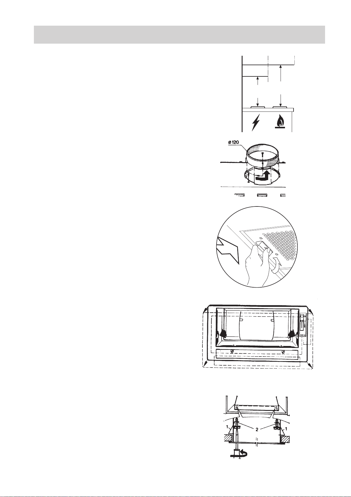
l Depois de instalado, o exaustor deve estar pelo
menos 65 cm acima dos queimadores eléctricos
ou 75 cm acima de queimadores a gás ou
queimadores mistos. (Fig. 3).
Utilização do exaustor de cozinha
l Não deverá cozinhar-se qualquer comida flam-
bee por baixo do exaustor.
l A utilização de uma chama desprotegida é
perigosa para os filtros e poderá provocar
incêndios.
l Nunca deixar uma fritadeira ou frigideira sobre
um fogão/placa. O óleo contido na frigideira
pode inflamar-se espontaneamente devido ao
sobre-aquecimento.
l Deve proceder-se à troca e limpeza do filtro a
intervalos regulares. A não observação destes
intervalos poderá provocar o risco de incêndio
em consequència do depósito de gordura.
Nota! Se deflagrar um incêndio; Desligar o
exaustor e a zona de aquecimento; Cobrir o fogo;
Nunca usar água.
Atenção
l Mesmo quando já não utilizar o exaustor, devem
evitar alguns riscos. Desligar o aparelho da
tomada e cortar o cabo de alimentação na
entrada do exaustor. Consultar as autoridades
para obtenção de informações sobre como
proceder para deitar fora o aparelho.
l O cabo de alimentação deverá estar recolhido
para que não haja risco de danos. Perigo!
36
Page 4
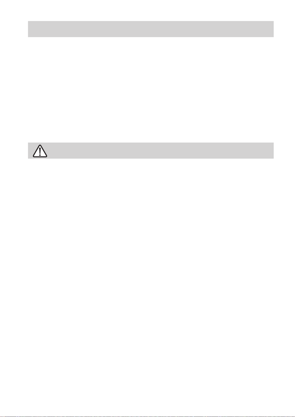
Descrição do aparelho
A.Painel dos interruptores de iluminação e de
selecção de velocidade do motor.
B.Grelha metálica do filtro (filtro para gordura)
A
C.Caixa de cobertura
D.Luz de iluminação da placa
Acessórios incluídos de origem
l Parafusos:
l Tubo de saída equipado com válvula anti-
retorno.
Função
O exaustor poderá ser utilizado das seguintes
formas:
- Versão de extracção
- Versão de reciclagem
Extracção
O ar é descarregado através de tubos que devem
ser ligados por anel de ligação ou válvula antiretorno (Fig. 2) no topo lateral do exaustor.
Atenção! Na posição horizontal, o tubo de saída
deve estar ligeiramente inclinado (cerca de 10º) e
dirigido para cima para descarregar facilmente o ar
da cozinha para o exterior.
0
1
2
3
Fig. 1
A
B
C
D
Ø 120mm
O exaustor não pode estar ligado a
canos de saída de combustível
(caldeiras, sistemas de aquecimento,
esquentadores, etc.).
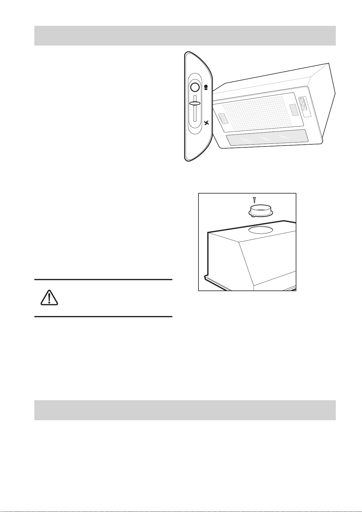
Reciclagem
O ar é filtrado pela passagem através de um filtro
de carvão activo e em seguida é recirculado
novamente para o interior da cozinha.
O ar filtrado é descarregado através de um tubo
120 mm que atravessa o armário e cuja saída fica
por cima deste.
Acessórios Especiais
Filtro de carbono
Quando o exaustor é utilizado no modo de
recirculação, deverá ser usado um filtro de carbono
activo.
Encomenda ao fornecedor da marca
PNC 941 196 401
Fig. 2
37
Page 5
Instalação
Desembalar
Verificar se o exaustor não está danificado. Os
danos de transporte deverão ser imediatamente
transmitidos a um responsável do serviço de
assistência, falhas e eventuais pormenores em falta
deverão ser imediatamente transmitidos ao
vendedor.
É favor guardar o material de embalagem para que
as crianças pequenas não possam brincar com ele.
Colocação
O exaustor deve ser montado na parede.
Depois de instalado, o exaustor deverá ficar pelo
menos 65 cm acima dos queimadores eléctricos e
75 cm acima de queimadores a gás ou queimadores
mistos. (Fig. 3).
Fig. 3
Fig. 4
Min
65 cm
Min
75 cm
Ligação Eléctrica
O exaustor tem um cabo de alimentação com ficha
moldada com ligação à terra que deverá ser ligada
a uma tomada de parede de 230 V.
O comprimento do cabo de alimentação é 1,2m.
Montagem do exaustor
l Montar a ligação de saída de ar ou a válvula
anti-retorno (ligação baioneta, meia volta para a
direita) (Fig. 4).
l Retirar a grelha metálica do filtro. Dobrar os
grampos para cima e pressionar a patilha
deslizante. (Fig. 5).
l Retirar a caixa de cobertura pressionando as
duas molas (Fig. 6).
l Montar o extractor do exaustor na abertura do
armário e empurrá-lo para cima por forma a que
as duas molas (1-Fig. 7) de lado encaixem por
cima da placa de suporte.
Fig. 5
Fig. 6
l Apertar os parafusos (2-Fig. 7).
l A caixa pode ser mais apertada ao armário com
os quatro parafusos de 2,9 x 16 mm.
l Substituir a caixa de cobertura e apertar os
filtros metálicos para gordura.
Fig. 7
38
Page 6
Modo de Extracção
l Ligar a saída de ar à magueira de saída do fumo.
l Na versão EFG 732 X, verificar se as duas
folhas internas S (Fig. 8) estão abertas.
Modo de Recirculação (com filtro
de carbono)
l Retirar a grelha metálica do filtro para gordura.
Dobrar as molas para cima e pressionar a patilha
deslizante (Fig. 5).
l Montar o filtro de carbono no lado da lâmpada 1
(fig. 9) pressionando as 2 pontas vermelhas, 2,
do filtro e encaixar o filtro para cima no
exaustor.
l Voltar a montar o filtro metálico para gordura.
l A corrente de ar é desviada para a frente ou para
os lados para o interior da cozinha de forma
adequada.
l O exaustor com a denominação EFG 732 X está
equipado com duas paredes internas (fig. 9) por
detrás do filtro para gordura. Estas paredes
encontram-se abertas quando se procede à
entrega do aparelho e deverão ser fechadas antes
de se montar o filtro para gordura.
Fig. 8
S
Fig. 9
S
2
2
S
1
S
Utilização do Exaustor
Selecção de velocidade
O exaustor está equipado com um motor
de três velocidades regulado por um
interruptor deslizante. Para um
funcionamento óptimo, recomenda-se
a utilização de velocidades baixas
em condições normais e velocidades
altas para determinadas situações de
odores fortes e concentração de vapor.
Recomenda-se a ligação do exaustor
alguns minutos antes de se começar a
cozinhar e o funcionamento até que
todos os odores tenham sido eliminados.
Luz de funcionamento
A luz de funcionamento do exaustor liga-se e
desliga-se independentemente do botão de
iluminação.
Ventilação correcta
Para que o exaustor de cozinha funcione
correctamente, as janelas da cozinha deverão estar
fechadas. Em vez disso, deverá estar aberta uma
janela numa divisão adjacente.
0
1
2
3
Fig. 10
A saber
Se o exaustor estiver a funcionar em simultâneo
com um queimador ou uma lareira que dependam
do ar ambiente (por exemplo, gás, diesel, carvão
ou aquecedores a madeira, esquentadores, etc.), é
necessário ter atenção, pois quando o exaustador
extrai o ar, remove o ar ambiente necessário ao
queimador ou à lareira para a combustão.
Isto não é válido se o exaustor for utilizado no
modo recirculação.
39
Page 7

Manutenção
Antes de executar qualquer operação
de manutenção, desligar o exaustor
da corrente.
Filtro para gordura
Este filtro serve para reter as partículas de gordura
em suspensão.
Para limpar, lavar com água quente e detergente
biodegradável.
Deixar secar antes de voltar a montar. Limpar,
pelo menos, uma vez por mês.
Remova o filtro
encaixes (Fig. 5).
l (Só EFG 732): Retirar a tira plástica central Z
por forma a libertar os dois painéis filtrantes
(Fig. 11).
Limpe igualmente os suportes.
Filtro de carbono
Este filtro dissolve os odores da comida.
Deverá ser trocado todos os 6 a 8 meses em
condições normais de utilização.
O filtro de carbono nunca deve ser lavado.
Para trocar o filtro de carbono:
l Remover o filtro para gordura
l Retirar o filtro de carbono usado pressionando
as duas pontas vermelhas (2-Fig. 9) e puxá-lo
para a frente.
l Montar o filtro de carbono novo primeiro no
lado da lâmpada do exaustor (1-Fig. 9),
pressionar as duas pontas vermelhas do filtro e
dobrar o filtro para cima no exaustor.
l Voltar a montar o filtro para gordura.
: Use a pega para retirar o filtro dos
Z
Fig. 11
Fig. 12
Limpeza
Para limpar o exterior do exaustor, utilizar um
pano embebido em alcóol desnaturado ou
detergentes líquidos neutros. Nunca se devem
utilizar produtos com abrasivos.
Atenção
A não observação das regras de limpeza do
aparelho, troca e limpeza dos filtros pode provocar
incêndios. Recomenda-se, portanto, a observação
destas instruções.
Trocar os elementos da
iluminação
l Desligar o exaustor da corrente.
l Abrir a cobertura da luz desenrolando os trincos
no sentido contrário ao dos ponteiros dos
relógios 1 (Fig. 12 e 13).
Fig. 13
l Retirar a lâmpada antiga do suporte e substitui-
la por uma de categoria igual.
EFG 732 X está equipado com 2 lâmpadas PL de 9
W (Fig. 12)
EFG 532 X está equipado com 1 lâmpada PL de 11
W (Fig. 13)
40
Page 8

Desmontagem do exaustor
l Retirar o filtro metálico para gordura e a caixa
de cobertura.
l Retirar os 4 parafusos adicionais da moldura.
l Desapertar os parafusos nas duas molas de
fixação (Fig. 14).
Fig. 14
l Empurrrar com uma chave de parafusos plana
para dentro do orifício das molas de fixação
(esquerda e direita) e empurrar cada uma das
molas de fixação para dentro (Fig. 15).
l Ao mesmo tempo, puxar o exaustor (esquerda e
direita) para fora do armário.
Fig. 15
Se o exaustor não funcionar
Antes de contactar o serviço
Verificar se a ficha está ligada à tomada da parede
e que não há nenhum fusível queimado. Não
proceder a quaisquer operações que possam causar
perigos ou danificar o produto. Se o problema
persistir, contacte o seu distribuidor ou um agente
autorizado de assistência técnica.
Assistência técnica e peças
sobressalentes
A assistência técnica e as peças sobressalentes
poderão ser obtidas através do seu distribuidor ou
do “Electroservice”
Quando pede assistência ou encomenda peças
sobressalentes deverá estar apto a indicar o número
do produto e a denominação do modelo. Encontra
esta informação na etiqueta de identificação.
Se remover o filtro para gordura, encontra a
etiqueta de identificação por trás.
Modelo:________________________________________
Número do
produto:_____________________________
Data da
compra:________________________________
41
Page 9

Dados Técnicos
Modelo EFG 732 X EFG 532 X
Capacidade Máxima 450 m3/h *286 m3/h 450 m3/h *286 m3/h
Mínima 197 m3/h 197 m3/h
Dimensão Altura 302 mm 302 mm
Largura 748 mm 548 mm
Profund. 302 mm 302 mm
Iluminação 2 x PL 9 W 1 x PL 11 W
Filtro para gordura 1 peça 1 peça
Tensão de Ligação 230 V 230 V
Classe de Segurança Eléctrica Classe 1 Classe 1
Consumo máximo 204 W 197 W
*) Válido quando o exaustor é utilizado com filtro de carbono activo (recirculação)
dimensões EFG 732 X
160
302
283
302
70
710
4,5
748
dimensões EFG 532 X
160
302
283
510
4,5
302
42
70
548
Page 10

Contents
Safety instructions .............................................................................................................. 44
Description of the appliance .............................................................................................. 45
Function .................................................................................................................................................................45
Exhausting .............................................................................................................................................................45
Recycling ...............................................................................................................................................................45
Special accessories ............................................................................................................ 45
Installation ........................................................................................................................... 46
Unpacking..............................................................................................................................................................46
Placement ..............................................................................................................................................................46
Electrical connection .............................................................................................................................................46
Mounting of hood ..................................................................................................................................................46
Exhausting mode ...................................................................................................................................................47
Recirculation mode (with carbon filter) ................................................................................................................47
Using the hood .................................................................................................................... 47
Speed regulation ....................................................................................................................................................47
Work light ..............................................................................................................................................................47
Correct ventilation .................................................................................................................................................47
Important to know ...............................................................................................................47
Maintenance......................................................................................................................... 48
Grease filter ...........................................................................................................................................................48
Carbon filter...........................................................................................................................................................48
Cleaning.................................................................................................................................................................48
Changing the lighting elements .............................................................................................................................48
Demounting of the hood ........................................................................................................................................49
If the hood does not function............................................................................................. 49
Service and spare parts ..........................................................................................................................................49
Technical data...................................................................................................................... 50
EFG 732 X dimensions .........................................................................................................................................50
EFG 532 X dimensions .........................................................................................................................................50
43
Page 11

Congratulations to your new Cooker Hood
Thank you for your choice of an Electrolux product. We are convinced that you will have
great use and pleasure from your new cooker hood.
Before you use the cooker hood we recommend that you read through the whole user
manual giving a direct description of the cooker hood and its functions.
To avoid the risks, that are always present when you use a product driven by electricity, it
is important that the cooker hood is installed correctly and that you read the safety instructions carefully to avoid misuse and hazard.
Save the instruction manual and keep it available at use of the cooker hood
Safety instructions
At installation and service
l The cooker hood is made for normal households
with normal cooking. If it is used for other
purposes there is a risk of damage which is not
covered by the warranty.
l All eventual electric installation has to be
carried out by a qualified electrician. The
installation of the hood should be made by a
person with enough knowledge. Installation
made otherwise could lead to loss of performance and even injuries and /or damage on
properties.
l The hood cannot be connected to flues of other
appliances that run on energy sources other than
electricity.
Please, keep to the provisions of official directives regarding the question of fumes discharge.
l When the hood is used at the same time of other
appliances that run on energy sources other than
electricity, provision must be made for an
adequate supply of air.
l When installed, the hood must be not less than
65 cm. above electric burners or 75 cm. above
gas or mixed-fuel burners. (Fig. 3).
At use of cooker hood
l No food must be cooked flambee underneath the
hood.
l The use of an unprotected flame is dangerous
for the filters and could cause fires.
l Never leave the deep-frying or frying pan over a
cooker/hob. The oil contained in the pan may
spontaneously ignite through overheating.
l Observe the filter change or cleaning intervals.
Failure to observe these intervals may cause the
risk of fire through fat deposition.
Note! If a fire starts; Switch of the cooker hood
and the heating zone; Cover the fire , Never use
water.
At disposal
l Help to avoid damages even when the cooker
hood should be disposed. Disconnect the power
plug and cut the power cord at hood inlet. Check
with the authorities for information of how to
proceed for disposal.
l The power cord should be drawn so that there is
no risk of damage. Hazard!
44
Page 12

Description of the appliance
A.Motor and lamp switch panel
B.Metal filter grill (grease filter)
C.Housing cover
D.Hob light
Standard accessories included:
l Screws for mounting
l Duct with no return valve
A
0
1
2
3
A
B
Function
The hood may be used as follows:
- For air exhausting
- For air recycling
Exhausting
The air is vented outside by means of pipes to be
connected to the duct supplied (bajonet coupling +
fixing screw) with no return valve (Fig. 2) on top
side of the hood.
Attention! In the horizontal runs the duct must be
slightly slanted (about 10°) and directed upwards
to vent the air easily from the room to the outside.
The hood cannot be connected to flues
of other appliances that run on energy
sources other than electricity.
Recycling
The air is filtered through a carbon filter and
recirculated into the room. The filtered air is
discharged by means of a Ø120 mm pipe which
goes through the cupboard and whose outlet is
above the cupboard.
This version is used when there is no exhaust duct
for venting outdoors or when it is impossible to
install one.
C
D
Fig. 1
Ø 120mm
Fig. 2
Special accessories
Active carbon filter
When the hood is used in recirculation mode an
active carbon filter should be used.
Order by the retailer
PNC 955 101 116 (B,CH,D,Sk)
941 196 401 (P)
45
Page 13

Installation
Unpacking
Check that the cooker hood has no damages.
Transportation damages should immediately be
reported to the one responsible for the transport
Damages, faults and eventually missing details
should immediately be reported to the seller.
Take care of the packing material so that small
children cannot play with it.
Placement
The hood is to be mounted in a wall cupboard.
When installed, the hood must be not less than 65
cm. above electric burners or 75 cm. above gas or
mixed-fuel burners. (Fig. 3).
Fig. 3
Min
65 cm
Min
75 cm
Electrical connection
The hood has a power cord with moulded plug
with earth connection to be connected to a wall
outlet of 230 V.
The power cord length is 1,2 m.
Mounting of hood
l Fit the 120 mm air outlet connector with no
return valve (bayonet connection, one half turn
to the right) (Fig. 4).
l Remove the metal grease filter grill. Fold the
grips upwards and press the locking slide in at
the side(Fig. 5).
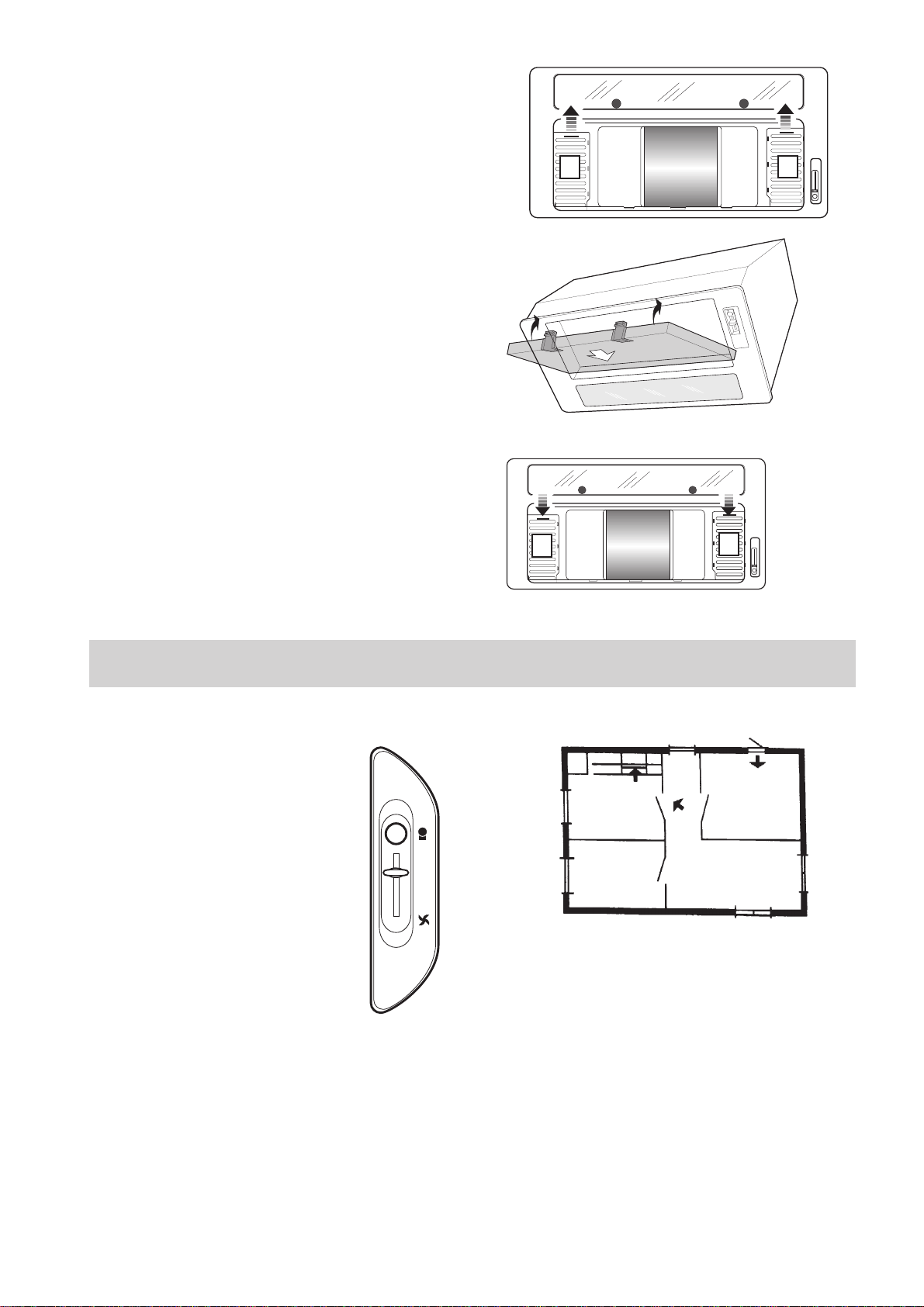
l Take the housing cover off by pressing the two
spring clips (Fig. 6).
l Fit the extractor hood into the opening in the
cabinet and press it upwards in such a way that
two springs (1-Fig. 7) on the side notch into
place above the supporting plate.
Fig. 4
Fig. 5
Fig. 6
l Tighten screws (2-Fig. 7).
l The housing can be further fastened to the
cabinet with the four 2,9 x 16 mm screws.
l Replace the housing cover and clip in the metal
grease filters.
Fig. 7
46
Page 14

Exhausting mode
l Connect the air outlet to the smoke exhaust
hose.
l On the version EFG 732 X check that the two
internal shutters S (Fig. 8) are open.
S
S
Recirculation mode (with carbon
filter)
l Remove the metal grease filter grill.
Fold the grips upwards and press the locking
slide in at the side (Fig. 5)
l Fit the carbon filter into the lamp side 1 (Fig. 9)
by pressing the two red lugs, 2, of the filter in
and clip the filter in upwards into the hood.
l Refit the metal grease filter.
l The current of air is to be diverted forwards or
sideways into the room in a suitable fashion.
l The hood with the denomination EFG 732 X has
two internal shutters S (fig. 9) behind the grease
filter. These are at delivery open. Before mounting the carbon filter they should be shut.
Fig. 8
S
Fig. 9
2
2
1
S
Using the hood
Speed regulation
The hood has a three speed motor
regulated with a slide switch. For
the best performance, we recommend using the lower speeds in
normal conditions and the highest
speed in particular cases of strong
odour and vapour concentration.
We recommend starting up the
hood a few minutes before cooking and keeping it running until all
the odours have been eliminated.
Work light
The hood work light is independently switch on
and off with the proper push-button switch.
Correct ventilation
To have the cooker hood working correctly the
windows in the kitchen should be closed. In stead a
window in an adjacent room should be open.
0
1
2
3
Fig. 10
Important to know
If the hood is run at the same time as a burner or
fireplace that depend on ambient air (for example
gas, Diesel, coal or wood heaters, water heaters,
etc.) be careful, because the hood, when it exhausts
the air, removes the ambient air required by the
burner or fireplace for combustion.
Not valid if the cooker hood is used in
recirculation mode.
47
Page 15

Maintenance
Before performing any maintenance
operation, disconnect the hood from
the electricity.
Grease filter
This serves to hold the grease particles in suspension. The metal filter should be washed every
month with warm soapy water or, if possible, in the
dishwasher (60°C).
To remove the metal grease filter, fold the grips
upwards and press the locking slide in at the side
(Fig. 5). Leave to dry before refitting it.
l (Only EFG 732): remove central plastic strip Z
to free the two filter panels (Fig. 11).
Clean the panels support as well.
Carbon filter
This filter dissolves cooking odours.
It should be changed every 6-8 months in normal
use. The carbon filter must never be washed.
To exchange the carbon filter:
l Remove the grease filter
l Take the old carbon filter out by pressing in the
two red lugs (2-Fig. 9) and pull it out forwards.
l Fit the new carbon filter first on the lamp side of
the hood (1-Fig. 9), press the two red lugs of the
filter and clip the filter upwards into the hood.
l Refit the grease filter.
Z
Fig. 11
Attention
Failure to observe the rules for cleaning the appliance and changing and cleaning the filters may
cause fires. Therefore, we recommend observing
these instructions.
Cleaning
To clean the outside of the hood use a cloth moistened with denatured alcohol or neutral liquid
detergents. Never use products containing
abrasives.
Changing the lighting elements
l Disconnect the hood from the electricity.
l Open the light cover by turning the latches
counterclockwise 1 (Fig. 12 and 13).
l Pull the old lamp out of the holder and replace it
with a new of same rating
EFG 732 X has 2 PL lamps of 9 W (Fig. 12).
EFG 532 X has 1 PL lamp of 11 W (Fig. 13).
Fig. 12
Fig. 13
48
Page 16

Demounting of the hood
l Remove the metal grease filter and the housing
cover.
l Remove the 4 additional screws from the frame.
l Loosen the screws on the two fixing springs
(Fig. 14).
Fig. 14
l Push a flat screw driver into the hole for the
fixing springs (left and right) and push each of
the fixing springs inwards (Fig. 15).
l At the same time, pull the hood (left and right)
out of the cabinet.
Fig. 15
If the hood does not function
Before you make contact to service
Check that the power plug is connected to the wall
power outlet and that no fuse is blown. Do not do
any operations that can cause hazard or damage to
the product. If the problem remains contact your
dealer or an approved service company
Remember to save the purchase recite and the
Warranty card (only used in some countries)
Service and spare parts
Service and spare parts you will get via your dealer
or service company.
When you order service or spare parts you should
be ready to give the product number and model
denomination. This information you will find on
the rating label.
Take away the grease filter and you will find the
rating label behind.
Model:
Product number:
Date of purchase:
49
Page 17

Technical data
Model EFG 732 X EFG 532 X
Capacity Max 450 m3/h x) 286 m3/h 450 m3/h x) 286 m3/h
Min. 197 m3/h 197 m3/h
Dimension Height 302 mm 302 mm
Width 748 mm 548 mm
Depth 302 mm 302 mm
Light 2 x PL 9 W 1 x PL 11 W
Grease filter 1 pc 1 pc
Mains Voltage 230 V 230 V
Electric safety class Class 1 Class 1
Power rating total 204 W 197 W
x)
Valid when the hood is used with carbon filter (recirculation)
EFG 732 X dimensions
160
302
283
302
70
710
4,5
748
EFG 532 X dimensions
160
302
283
510
4,5
302
50
70
548
Page 18

Page 19

L 583 1007 ACK
 Loading...