

Page 1
Operating instructions
Mode d'emploi
Bedienungsanleitung
Gebruiksaanwijzing
Istruzioni per l'uso
Page 2
Part 1 INSTALLATION
INSTRUCTIONS
must be of the room sealed or balanced
flue type. If other types of flue or appliance are fitted ensure that there is an
adequate supply of air to the room.
1 - GENERAL INFORMATION
This built-in group is especially designed to
be fitted inside a decorative canopy. Featuring
a very powerful fan unit this appliance allows
the decorative canopy not only to look
attractive but also to be very good in performance. Thanks to the pyramid shape and the
compact size, this group can be easily fitted in
slim lined canopies.
To ensure a satisfying use from this appliance
we recommend to comply with the installation and operating instructions carefully.
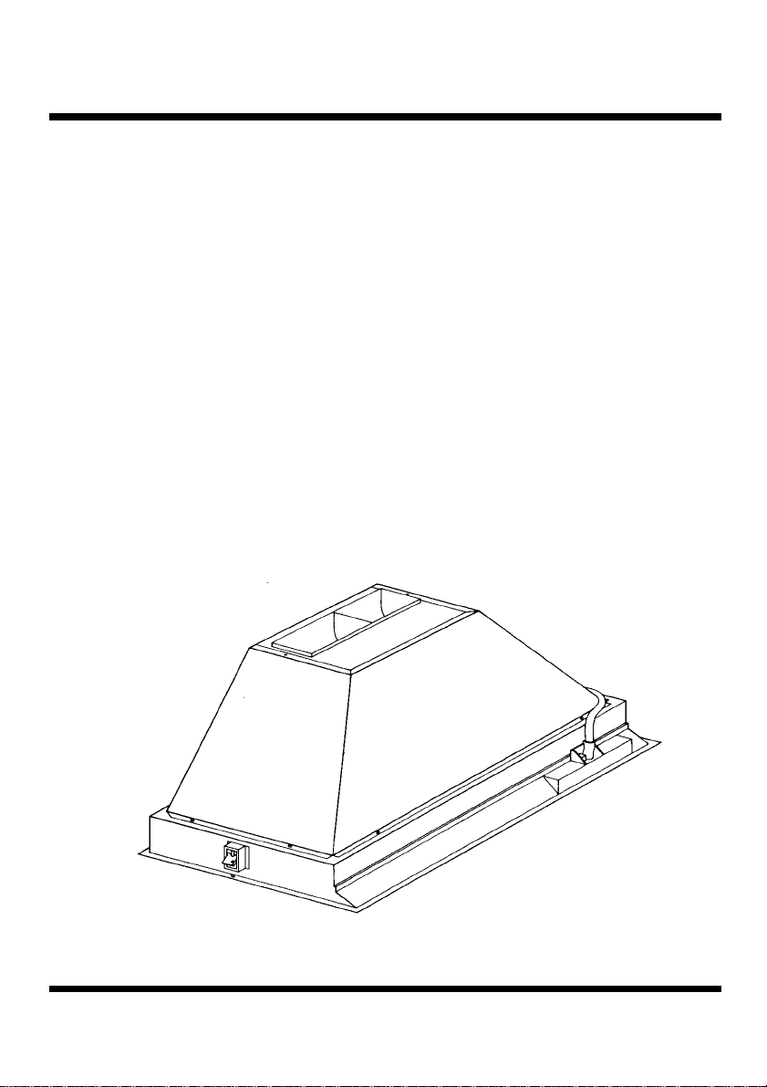
2 - COMPONENTS
The appliance is made up of the following
components (fig. 1):
- N. 1 cooker hood C
- N. 1 evacuation spigot R
3 - SAFETY WARNINGS
3.1 - When used in the extraction mode the
cooker hood ducting must not be connected
to a central heating flue (radiators or water
heaters). In connection with the discharge
of exhaust air, the requirements of the
authorities concerned have to be observed.
3.2 - Before connection to the mains supply
make sure that the mains voltage corresponds with the voltage on the rating plate.
3.3 - Connect the hood to the mains supply via
a double pole switch which has 3mm clearance between the contacts.
3.4 - This appliance must be earthed.
3.5 - When installed, the hood must be positioned at least 65 cm above a cooking
appliance.
3.6 - Never do flambé cooking under this cooker hood.
3.7 - Never leave frying pans unattended during use as overheated fat and oil may catch
fire.
3.8 - Before carrying out any kind of maintenance or cleaning, disconnect the hood
from the mains supply.
3.9 - If the room where the cooker hood is to
be used contains a fuel burning appliance
such as a central heating boiler then this
4 - INSTALLATION
This hood is supplied with specially designed
butterfly type fixing brackets S (fig. 1) and
can be installed following these instructions:
4.1 - Fitting the group inside a decorative
canopy
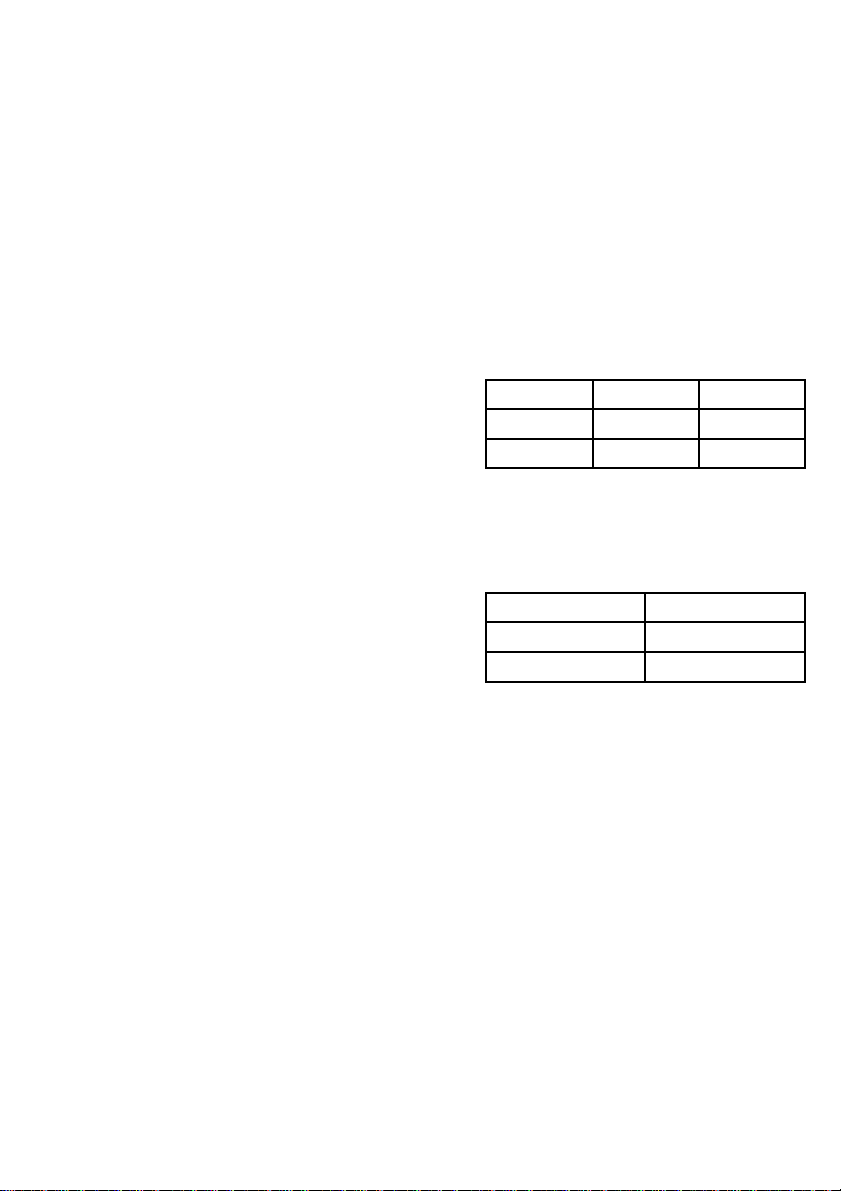
1 - Cut a rectangular hole into the underside
of the canopy in accordance with the table
below leaving 15 mm from the lateral and
back edges of the canopy (fig. 2):
Hood Measure A Measure B
540 mm 523 mm 333 mm
720 mm 703 mm 333 mm
2 - Cut a hole in the upper part of the canopy, where you prefer to have the air-outlet, according to the diameter of the duct
and following the instructions of the table
below.
DUCT MEASURE C
Ø 100 mm 105 mm
Ø 120 mm 125 mm
3 - Fix the ducting spigot R in the upper
part of the hood (see paragraph 4.3 1b).
4 - Insert the upper part of the hood through
the hole cut in the underside of the canopy
(ensuring that the butterfly catches S are
loose enough so that they spring open) and
hook onto the base of the canopy.
5 - Access to the securing screws in the butterfly brackets is through two holes in the
lower casing as illustrated in fig. 3. Turn the
screws clockwise until the hood is firmly
attached to the cabinet.
4.2 - Electrical connection
WARNING: THIS APPLIANCE
MUST BE EARTHED
1 - It is imperative that the safety measures
contained in paragraphs 3.2, 3.3, 3.4 are
strictly observed.
2 - Before connection to the mains supply
check that the circuitry is sound. After the
connection has been tested switch on the
Page 3

mains supply and check that the worktop
illumination lamp and three fan speeds function correctly.
4.3 - Ducting or recirculation fitting
1 - Ducting fitting:
a - The cooker hood can be ducted to the
outside using either a fire retardant rigid or
flexible ducting of 100 or 120 mm diameter.
The choice is left to the installer (fig. 4).
b - The ducting spigot R supplied has an air
outlet of 100 mm diameter. To adapt the
spigot to 120 mm diameter cut along the
slot as illustrated in fig. 5 using a sharp knife.
c - Connect the ducting spigot R to the
cooker hood by placing the spigot over the
rectangular outlet on the top of the upper
assembly and secure the spigot using two of
the screws provided as illustrated in fig. 6.
The ducting can now be connected to the
spigot A ensuring that an air tight sealed is
obtained.
d - If the hood is provided with the charcoal
filter fitted, the filter should be removed (see
paragraph 3.3 2 2nd Part).
2 - Recirculation fitting:
a - Fit the charcoal filter inside the hood
(see paragraph 3.3 2, 2nd Part).
b - Connect spigot R to the hole cut on top
of the canopy for the air outlet in the same
way as for the ducting fitting.
c - When the hood is installed in the recirculation mode, the air is recirculated into
the kitchen through a pipe connecting spigot
R to the upper part of the canopy (fig. 7).
Part 2 OPERA TION AND
MAINTENANCE
INSTRUCTIONS
1 - SAFETY WARNINGS
It is most important that all the warnings
contained in paragraph 2 of the Installation instructions are strictly observed.
Moreover, special attention should be paid
to the following warnings appertaining to
the use and maintenance of the cooker hood.
1.1 - This appliance is designed to be operated
by adults.
1.2 - The grease filters and charcoal filters
should be cleaned or replaced as recommended by the manufacturer or more
frequently if the hood is used consistently
for more than 4 hours per day.
1.3 - When using a gas hob in conjunction with
this cooker hood never leave the burners
of the hob uncovered while the hood is in
use, or when the pans have been removed. Switch off the gas when removing
the pan.
1.4 - Always ensure that the flame is kept at
the correct intensity to prevent the flame
from licking round from the bottom of
the pan; this will save energy and will
avoid a dangerous concentration of heat.
1.5 - This hood should be used for the purpose
for which it was designed; to remove
odours from cooking in the kitchen.
2 - OPERATION
2.1 - Functions
Controls are located on the lower part of the
appliance and control the power to the fan, the
worktop illumination and the speed of the fan.
2.2 - Controls
The cooker hood functions are controlled by
three slide switches as illustrated in fig. 8.
- Switch L controls the worktop illumination,
- Switch M controls the power to the fan motor,
- Switch V controls the fan speed
Position 1, low speed, should be selected
when simmering or using one pan; which
keeps the noise level at a minimum.
Position 2, medium speed, should be selected
for normal cooking. This speed offers the best
Page 4

ratio of air capacity and noise level.
Position 3, top speed, should be selected when
frying or cooking food with strong odours,
even for sustained periods.
3 - MAINTENANCE
Regular maintenance and cleaning will ensure good performance and reliabilty, while
extending the working life of the hood. Special attention should be taken to ensure that
the grease filters and charcoal filters (when
the hood is used in the recirculation mode) are
cleaned and replaced as recommended.
3.1 - Thin synthetic filter
1 - Cleaning:
This filter cannot be washed and should be
replaced every two months. If the filter is
provided with a saturation indicator, replace
when the violet colour of the dots which are
visible from the outside is spread over the
whole surface of the filter.
2 - Replacing:
The filter is located on the reverse side of the
metal grille. To replace it first open the grille
as illustrated in fig. 9 and then remove the
metal wire clips. Replace by reversing the
operations.
3.2 - Metal grease filters
1 - Cleaning
The metal grease filters replace the metal
grille completely and should be cleaned
every two months with normal usage. Their
compact dimensions allow them to be
cleaned in a dishwasher. Before replacing
the filters ensure that they are dry.
2 - Removal of metal filter for cleaning
Remove one filter a time (2 filters are required for the cooker hood in 54 cm and 3 filters
for the hood in 72 cm) supporting them with
one hand. Apply slight inward pressure to the
actuators to release the securing bolts as
illustrated in fig. 11. When replacing the filters care should be taken that the securing
bolts face downwards.
3.3 - Charcoal filter
1 - Working:
In the recycling mode the charcoal filter
absorbs smells and odours during cooking
until it reaches saturation point.
The charcoal filter cannot be cleaned and
should be replaced at least every 4 months or
more frequently if the hood is used consistently.
2 - Replacement:
a - To remove the charcoal filter first open the
lower grille or remove the metal filters as
instructed in paragraph 3.1 2a and 3.1 2b.
b - Remove the separating plate if your
cooker hood is in 54 cm and with metal
filters (fig. 12).
c - Remove the charcoal filter by pressing
inwardly on the two catches while pushing
the filter backwards and down as illustrated
in fig. 13.
d - The charcoal filter should be replaced by
reversing the operation.
3.4 - Worktop illumination
The hood may be fitted with a 15W fluorescent strip lamp or with two 40W lamps.
To replace them proceed as follows:
a - Remove one of the two plastic covers T
by loosening the fixing screw; the glass diffuser is retained in position by the metal
retaining lug L (fig. 14);
b - Slide the diffuser towards the side where
the plastic cover T has been removed until
the opposite end is free (arrow 1); Pull the
glass diffuser down slightly (arrow 2) and
then move it back in the opposite direction
until the lighting diffuser can be released
from the retaining lugs L (arrow 3) (fig.
15);
c - When replacing the fluorescent strip lamp
an identical replacement must be fitted rotating it trough 90 degrees;
replace the lamps fitted in the lampholders
with identical replacements;
d - Refit the glass diffuser by reversing the
operations.
3.5 - Cleaning
The interior and exterior of the hood should
be cleaned regularly to keep it looking like
new. Clean using a damp cloth wrung out in
hot water and mild household detergent and
dry with a soft cloth.
Always use non abrasive cleaning materials
especially when cleaning stainless steel surfaces.
Page 5

Page 6

Page 7

Page 8

Page 9

Page 10

Page 11

4324006 01 - 001005
 Loading...