

Page 1

MANUALE D'INSTALLAZIONE, D'USO E MANUTENZIONE
PAG.
1
FIM S.r.l. Via Fontedamo, 26
-
60035 JESI (AN)
-
ITALY
-
Tel. ++39 0731
61591
-
Fax. ++39 0731 606107
CAPPA AD ISOLA
ISLAND COOKER HOOD
INSEL - DUNSTABZUGSHAUBE
HOTTE ILÔT
CAMPANA A ISLA
EILAND WASEMSCHOUW
INSTALLATION, USE AND MAINTENANCE MANUAL PAG. 15
INSTALLATION, BEDIENUNG UND PFLEGE ANLEITUNGSBUCH PAG. 29
MANUEL D'INSTALLATION, D'EMPLOI ET D'ENTRETIEN PAG. 43
MANUAL DE INSTALLACION, USO Y MANTENIMENTO PAG. 57
INSTALLATIE-EN GEBRUIKSHANDLEIDING PAG. 71
Page 2

COD. 06067650
VER. CI
-L-
202-
Page 3

ADDENDUM 06067939
DE - Das Gerät muss installiert werden, so daß der Stecker sich in einer zugänglichen Lage befindet.
EN - The appliance must be installed so that the plug is accessible.
FR - L’appareil doit être installé de façon que la fiche soit accessible.
NL - Het apparaat dient so geïnstalleerd te worden dat de stekker bereikbaar.
IT - L’apparecchio deve essere installato in maniera tale che la spina sia accessibile.
ES - El apparato tiene que ser instalado en modoal que el enchufe se encuentre ubicado en una posición accesile.
NO - Apparatet må installeres slik at støpslet er tilgjengelig.
SE - Produkten måste installeras så att kontakten är lättillgänglig.
DK - Apparatet skal installeres og tilsluttes, så kontakten er tilgængelig.
FI - Tuote pitää asentaa niin, että pistoke on helposti irrotettavissa pistorasiasta.
Page 4
cm 65MIN
FILTRANTE
FILTERING
UMLUFTBETRIEB
FILTRANTE
FILTRADORA
RECIRCULATIE
ASPIRANTE
SUCTION
ABLUFTBETRIEB
ASPIRANTE
ASPIRADORA
AFVOER
FIG.1
FIG.2 FIG.3
Page 5
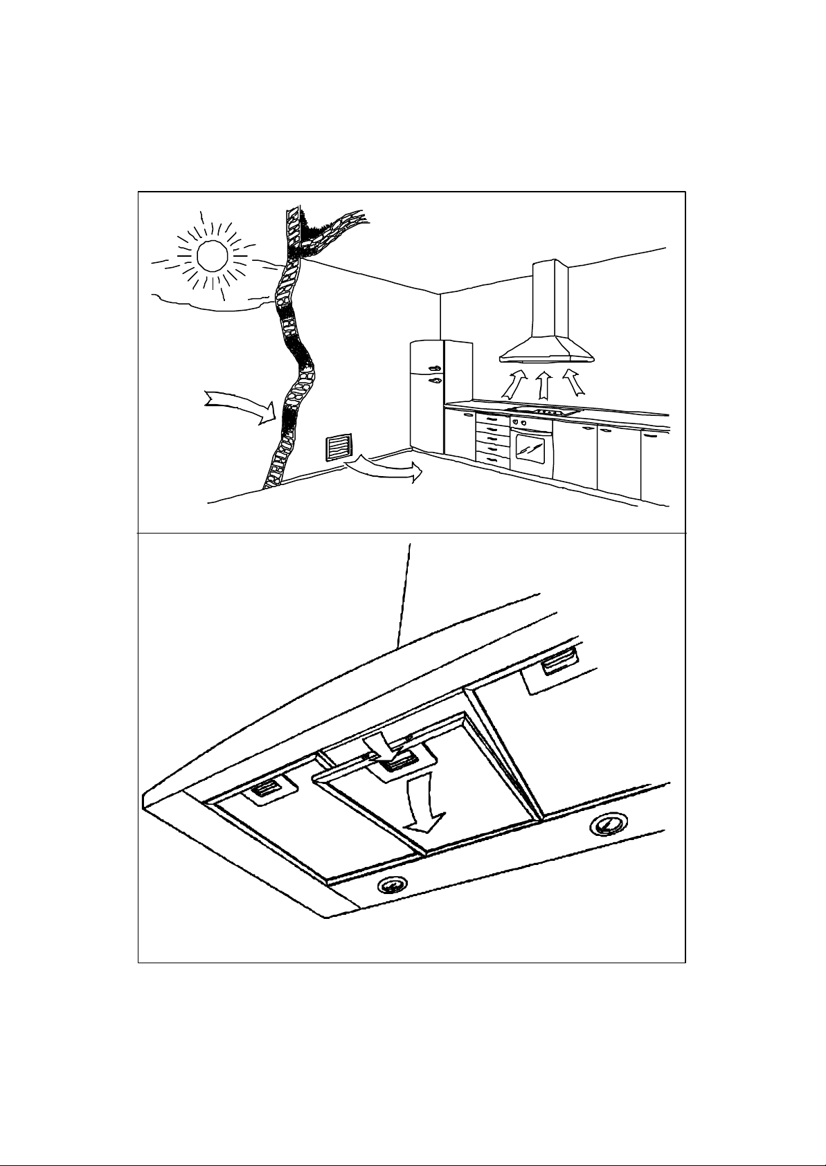
FIG.4
FIG.5
Page 6

FIG.6a
FIG.
FIG.7
FIG.8
Page 7

6
B
FIG.6b
FIG.9
FIG.10
FIG.11
Page 8

FIG.12
FIG.13
FIG.14
PERDITEDIPORTATADROPINAIR-DELIVERYPERTESDED
LUFTLEISTUNGSVERLUSTEPÉRDIDACAUDALDEAIRECAPACITEITSVERLIES
9m.
7m.
5m.
3m.
460
495
530
590
750m/h
9m.
7m.
5m.
3m.
3
420
445
460
495
750m/h
9m.
7m.
5m.
3m.
3
ÉBITD’AIR
375
400
415
440
750m/h
3
m/h
3
Page 9

• rimontare la plafoniera.
Per sostituire una lampada ALOGENA (FIG. 13) procedere come segue:
• smontare la cornice del faretto ruotandola in senso antiorari o;
• estrarre la lampada difettosa;
• prendere la nuova lampada evitando di toccarla direttamente con le dita, per es. arrotolandola
con carta;
• infilare i due spinotti della lampada nei fori appositi;
• rimontare la cornice del faretto ruotandola in senso orario.
11 PULIZIA
Per conservare in buono stato la cappa l’unica pulizia consentita, oltre quella dei filtri antigrasso è
quella della superficie esterna della cappa, detto MANTELLO.
Tenere pulito il MANTELLO rende più gradevole l’aspetto della cappa.
ATTENZIONE! Assicuratevi che sia esclusa l’alimentazione elettrica.
La sostanza detergente raccomandata è una soluzione di ACQUA e SAPONE
LIQUIDO NEUTRO. E’ molto importante che il sapone liquido sia privo di
granuli che possono graffiare la superficie.
La soluzione deve essere prima applicata su un panno morbido e poi a mano si
strofina il panno sul mantello. E’ importante seguire col panno il senso della
satinatura (VEDI FIG. 14).
E’ fatto assoluto DIVIETO di VERSARE LIQUIDI DIRETTAMENTE SULLA
CAPPA.
Il panno deve essere privo di bottoni, chiusure lampo, automatici o altro che
possa graffiare la superficie.
Si vieta l’uso di solventi chimici, prodotti aggressivi, granulosi o abrasivi,
benzine o similari che potrebbero compromettere l’aspetto superficiale del
mantello, specie quello verniciato.
Il rame utilizzato per la realizzazione delle cappe viene lavorato con speciali
vernici che ne impediscono il naturale processo di ossidazione. E’ vietato fare
uso di prodotti commerciali destinati al trattamento del rame che rovinerebbero
tale protezione.
La ditta costruttrice non risponde di danni sia funzionali che estetici causati da
pulizia fatta con prodotti inadatti o con modi inadeguati.
12 ACCESSORI OPZIONALI
Sono disponibili, venduti separatamente, questi accessori opzionali:
• FILTRI CARBONE (VEDI FIG. 6)
• CAMINO ESTETICO CON FERITOIE E DEFLETTORE PER VERSIONE FILTRANTE.
COOKER HOOD
1 GENERAL
The hood you have chosen is a decorative island hood and is to be mounted to hang directly from
the ceiling.
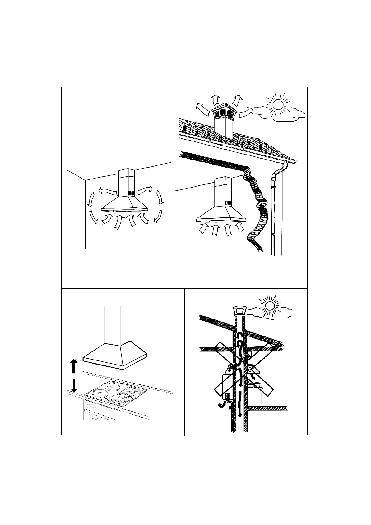
It is a SUCTION hood which can also be used as a FILTERING hood.
A SUCTION HOOD extracts air, fumes and vapours from the inside environment and then expels
them outside. It is not necessary to use carbon filters for purifying.
A FILTERING HOOD extracts air, fumes and vapours from the inside environment, purifies them
by means of carbon filters and then emits the purified air into the same environment. In this case,
the use of carbon filters is absolutely necessary (SEE FIG. 1).
Carbon filters are available separately and can be purchased as optional accessories (SEE
OPTIONAL ACCESSORIES).
Each hood is pre-assembled at the factory.
The user must arrange for the correct mounting of the chimney, the carbon filters if required and
the fixing of the hood to the ceiling. Connection of the hood to the domestic electric supply must
be carried out by qualified personnel who use standard tools, methods and components.
Indications on how to proceed are given below.
2 AFTER PACKAGING HAS BEEN OPENED . . .
. . . you will find the following material and documentation:
• the hood;
• this instruction manual; a technical drawing with the dimensions and position of the support
holes and the guarantee;
• the adjustable metallic support structure complete with screws for height adjustment;
• a plastic bag containing: pressure plugs complete with large screws and washers for fixing the
metallic structure to the ceiling; small screws for fixing the chimney to the metallic structure
and to the hood; bolts and washers for fixing the hood to the metallic structure.
3 BEFORE MOUNTING
Before mounting you should be aware of:
3.1) the power rating of the cooker:
- if it is below or equal to 7 kw (kilowatt), the hood should be mounted so that the
minimum distance between it and the top of the cooker i s not less than 65 cms;
- if it is above 7 kw (kilowatt), the manufacturer recommends that the distance be
increased by 2,5 cms for each extra KW delivered by the cooker top.
DISTANCE in cms = 65 + 2,5 x (POWER in KW - 7).
Page 10

WARNING! If the user decides to install the hood at
distances below 65 cms, the manufacturer declines any responsibility for
eventual damages caused by the hood due to strong heat or damages to
property or persons etc. caused directly or indirectly by any type of
malfunctioning breakdown or possible fire (SEE FIG.2).
3.2) Arrange for a socket outlet or standard connection to the electric mains at a suitable
distance; if the use of a plug is required, and the feed cable is not provided with one,
have a plug installed as per standard procedures;
3.3) if the hood is used as a suction hood, it is necessary to make a hole towards the
outside (i.e. in the open air) for the scavenging of the fumes.
WARNING! It is absolutely forbidden for the user to connect the air
discharge of the hood, when used as a suction hood, to boiler chimneys, gas,
fume or vapour scavenging chimneys or any other duct, even only ventilation
ducts, which have been used or will be used for other devices. Moreover, it is
not permitted to connect the scavenging pipe w ith fumes which are issued in
other adjacent rooms or wellholes, particularly if they contain fire-fighting
devices.
Any user who does not adhere to these instructions is risking his own life and the
lives of others. In this case, the manufacturer declines any responsibility (SEE
FIG.3).
If the previous conditions have been checked, the scavenging hole and pipe
must be of the same diameter as the hood outlet duct. For island hoods, the
scavenging hole can be made on the ceiling or on the side wall should the
hood be hung without touching the ceiling.
3.4) If the hood is used as a suction hood, it is necessary for qualified personnel to make a
hole for ventilation on the outside wall.
If the cooker is gas, it is not advisable to use the hood at the same time as fireplaces,
furnaces, gas or other fuel stoves, or water heaters which burn up oxygen from the
environment in order to function, and in any case depression in the cooker area must
be below 4 Pa (0.04 mbar) and the room must be sufficiently aired.
If in doubt, national and international standards precisely indicate the rules for the state
of art installation of gas systems and for environment air change, to avoid the possibility
of incomplete combustions with the risk of poisonous fumes being emitted (SEE FIG.4).
3.5) If the hood is to be used as a filtering hood, it is necesary to purchase the carbon filters
(SEE ACCESSORIES). The mounting instructions will be given at paragraph 4.3.
3.6) If the hood is to be used as a filtering hood, it is possible to purchase a decorative
chimney supplied with holes, and with a deflector, separately (SEE ACCESSORIES), to
convey the air flow in a more efficient manner.
4 MOUNTING INSTRUCTIONS
4.1 EQUIPMENT AND TOOLS
Before mounting, make sure you have the following equipment and tools:
• 1 screwdriver with a wide blade (about 8 mms), or a cross-notched screwdriver (with total
width of the blade about 4 mms);
• 1 screwdriver for height regulation (with blade about 5 mms);
• 1 drill with a nose suitable for building materials with the same diameter as the caps;
• a pencil or a small drawing pin to mark the positions of the holes on the wall;
• for suction use: pipe of the same diameter as the hood outlet duct in straight or curved
pieces, sufficient to convey the air towards the outside; clamp or small self -threading screw
for fixing. The pipe must be made of suitable material and namely: corrosion, heat and
flameproof;
• 1 hexagonal 10 mms spanner or a screwdriver;
• measuring tape.
4.2 DISMANTLING AND RE-POSITIONING OF THE ALUMINIUM GREASE FILTERS
To fix the hood to the ceiling or insert the carbon filters (when used for filtering see par. 4.3), it is
necessary to gain access to the inside, therefore the alluminium grease filters should be removed.
The grease filters should be re-positioned after mounting the hood or replacing spare parts, to
guarantee correct functioning.
TO EXTRACT a grease-filter (SEE arrow in FIG. 5):
• pull the small handle downwards.
TO RE- POSITION the grease-filter (SEE FIG. 5 opposite direction to the arrow):
• grip the grease filter;
• insert the back side of the grease filter into its groove;
• press the small handle spring;
• insert the front side of the grease filter into its groove;
• let the spring of the small handle go, so as to push the teeth into their slots.
4.3 FITTING AND REMOVAL OF CARBON FILTERS
To use the hood as a suction hood, read the following paragraph.
If you wish to use the hood as a filtering hood, it is necessary to fit the carbon filters.
Before fitting the carbon filters remove the alluminium grease filters as indicated at paragraph 4.2.
The carbon filters which contain activated carbon ARE OPTIONAL, and can be bought
separately.
There are two types of carbon filters.
Once the alluminium grease filters have been removed, it is possible to identify which type of filter
is suitable for the hood (FIG. 6).
To mount a filter of the type illustrated in FIG. 6a, proceed as followis:
• carefully observe the shape of the joints;
Page 11

• insert the back side into its groove;
• lift the front side of the carbon filter, until it is blocked;
• clamp the filter by rotating the two knobs at 90°.
To remove a carbon filter proceed as follows: (SEE FIG. 6a OPPOSITE DIRECTION TO THE
ARROWS):
• rotate the two knobs at 90°;
• pull the front side of the filter downwards;
• fully extract, by removing the back of the filter from the groove.
If the carbon filters are of the type illustrated in FIG. 6b, proceed as follows for mounting:
• grip the external part (without teeth) of the filter with both hands;
• pay attention to the shape of the motor inserts, you will have to follow this when rotating the
filters to block them;
• rest the edge of the filter with three teeth on one of the motor sides so that each tooth is in
the correct position to be fitted into the corresponding insert;
• make sure that the three teeth are correctly inserted and rotate the filter so as to ensure it is
fully blocked;
• to ensure that filter is correctly fitted, release your grip and try to move the filter away from
the motor towards the outside;
• if the filter does not m ove, it is correctly fitted;
• If the filter moves around or even falls, it is not correctly installed; in this case repeat the
above procedures until it is correctly fitted.
To remove both carbon filters proceed as follows:
(SEE FIG. 6b OPPOSITE DIRECTION TO THE ARROWS):
• rest the palm of the hand on the filter to be replaced;
• rotate the filter in the only possible direction;
• the filter teeth will come out of the grooves and you will feel that the filter is free to move;
• grip the filter and remove it from its housing.
4.4 FIXING PHASES
To fix the hood to the ceiling, act as follows:
• prepare the scavenging hole for fumes, if required;
• prepare the metallic structure;
• prepare the scavenging pipe, if required;
• prepare the decorative chimney;
• fix the body of the hood.
ATTENTION: some of the mounting phases must be carried out by 2 persons.
4.4.1 PREPARATION OF THE SCAVENGING HOLE
If the hood is to be used as a suction hood, the hole for fume scavenging must be made.
Before doing this, check paragraph 3.2 and 3.3.
If all the conditions have been respected, the scavenging hole should be of the same diameter as
the hood outlet manifold.
4.4.2 PREPARATION OF THE METALLIC STRUCTURE
On the island hood, it is necessary to arrange for the bearing structure attachments (SEE FIG. 7).
Take into consideration that the part of the metallic structure which is fixed to the ceiling is the
part with the slot shaped holes, not the part with the round holes.
Proceed as follows:
• according to the technical drawing (and to the sc avenging hole if the hood is to be used as a
suction hood), mark on the ceiling with a pencil, the position of the metallic structure support
holes. Trace the position of the holes with a cross shaped mark, because this helps to
identify the original position even if the drill nose moves;
• make the support holes using a suitable drill with nose for industrial building materials in the
marked positions;
• insert only the plastic part of the pressure plugs into the holes;
• bring the top part of the metallic support structure (with the slot shaped holes) into contact
with the ceiling where the fixing holes are positioned;
• insert the screws complete with washers, first of all into the metallic structure slots and then
into the plastic plugs on the ceiling; then tighten them using a screwdriver;
• mount the bottom part of the structure on the hood body, inserting the bolts into their
housings, and tightening them with the hexagonal spanner or screwdriver, depending on the
model.
4.4.3 PREPARATION OF THE SCAVENGING PIP E
If the hood is to be used as a suction hood, prepare the scavening pipe as follows:
• measure the distance to be covered by the pipe and prepare the correctly dimensioned
lengths;
• connect the lengths of pipe up to the scavenging hole;
• connect the pipe to the end which protudes from the ceiling and fix it in the most secure
manner (clamps, self-threading screws..), because it will have to left hanging up.
WARNING ! The pipe must be heat, flame and corrosion proof. The manufacturer
strongly advises against the use of reducers or pipes with a different diameter to the hood outlet
pipe, and pipes made of flexible aluminium (called “corrugated pipe“) because performance is
diminished.
The end part of the pipe, on the outside of the hole on the wall, must be of such a shape as to
avoid rain, gusts of wind or other foreign bodies getting into the pipe. Should there be any doubt,
contact anyone specialising in the installation of gas or ventilation systems.
Page 12

4.4.4 PREPARATION OF THE DECORATIVE CHIMNEY
It is always compulsory to fit the decorative chimney.
The decorative chimney is made up of 2 parts, one narrower and one wider, to be positioned one
inside the other and around the bottom metallic structure, resting on the hood body in the hollow
space.
The metallic structure always protudes above the two parts of the decorative chimneys (SEE FIG.
8).
4.4.5 FIXING OF THE HOOD BODY
The last phase in fixing the hood to the ceiling is the hood body.
Proceed as follows:
• preferably two persons should support the main body of the hood;
• for suction use, check that the hood outlet manifold is locked correctly inside the
scavenging pipe;
• align the lower metallic structure with the top one;
• slide the two parts of the structure one inside the other;
• based on the dimensions of the hood indicated on the drawing and the minimum distances
from the cooker par. 3.1, establish the correct height and tighten the vertical regulating
screws in their holes;
• raise the mobile part of the decorative chimney (the narrow part) until it touches the ceiling
support and block it by tightening the two side screws;
• block the lower part of the decorative chimney by clamping the two side screws near the
hood body.
5 ELECTRICAL CONNECTION
5.1 WARNING
As already mentioned, the electrical connection can only be carried out by qualified professional
personnel, using standard material and state of the art installation methods. The manufacturer
declines any responsibility for installations carried out by unskilled persons and for installations
which are not in conformity with the standard norms concerning electrical safety (both concerning
methods and materials).
5.2 ELECTRICAL TECHNICAL DATA
The elctrical technical data are visible inside the hood after the removal of the grease filters (see
par.4.2).
5.3 BEFORE ELECTRICAL INSTALLATION
Before making the electrical connection:
• check that the electrical data indicated are in conformity with the main voltage and frequency
values of the building where the hood is to be installed;
• check that the building is fitted with electric safety systems to protect against short circuits
and electric shocks systems, according to the laws in force;
• install an electric socket (or connection point) with a bipolar switch, having contacts with an
opening of at least 3 mms;
• if it is intended to install the hood with a plug, and the feed cable is not provided with one, a
standard plug must be purchased. This plug be easily accessible;
• always turn off the main voltage supply by means of the bipolar switch before connecting and
switch on again only when connections have been completed, tested and are safe.
5.4 CONNECTION TO THE POWER SUPPLY
The flexible feed cable supplied is already connected internally and emerges from the hood near
the air outlet duct.
It is possible to effect two types of electric installation:
• fixed installation;
• installation by means of plug on a socket .
In both cases connection to the power supply must be carried out only by qualified personnel and
in conformity with national and international standards, in order to guarantee electric safety, using
standard materials.
6. PRECAUTIONS TO BE TAKEN IF REPAIRS ARE TO BE
CARRIED OUT
Repairs, including the replacement of the feed cable if necessary, are to be carried out only by
qualified personnel, using standard methods, instruments and materials. Any repairs carried out
by others could prove to be dangerous and could be a fire risk.
7 INSTRUCTIONS FOR USE and PRECAUTIONS
Before using for the first time, ensure that all the points in the previous paragraph s have been
complied with concerning installation of the hood.
MOREOVER remember:
• not to cook “flambé” dishes, avoid flames directly underneath the hood;
• to avoid leaving on any hot plates which generate strong free flames underneath the
hood;
• to avoid any strong flames being issued from under saucepans at the sides;
• when frying, not to allow oil to splash or overheat in the pan, as this is a fire risk;
• before any cleaning or maintenance operation, disconnect the hood from the mains
supply, by means of the main switch or the bipolar switch or by removing the plug;
• if other gas equipment or equipment which consumes oxygen from the environment is
used, ventilation must be sufficient. For safe ventilation, maximum depression in the
room should not exceed 4 Pa (0,04 mbar) and there must be a hole on the outside
facing wall (suitably positioned and dimensioned);
Page 13

• never use the hood without the aluminium filters;
• keep the aluminium filters clean, taking into account the recommended cleaning
suggestions (see MAINTENANCE paragraph);
• replace the carbon filters (if the hood is used as a filtering hood), as indicated;
• turn on the hood motor before you start cooking;
• turn off the hood motor about 10 minutes after you have finished cooking.
8 POSITION OF THE CONTROLS
In the SLIDER version (SEE FIG.9) there are two slide switches.
Motor control switch ( ):
III motor ON switch: maximum speed;
II motor ON switch: intermediate speed;
I motor ON switch: minimum speed;
O m otor OFF switch: to switch the motor off.
Light control switch ( ):
I switch ON: lights on;
O switch OFF: lights off.
In the PUSH BUTTON control version (SEE FIG. 10), the controls are on the front of the hood:
III motor ON: switch maximum speed;
II motor ON: switch intermediate speed;
I motor ON: switch minimum speed;
O motor OFF: switch: allows you to turn the motor off;
to switch the lamps on or off.
In the ELECTRONIC control version (SEE FIG. 11) the controls and the display are concentrated
on one single panel. The functions activated are described as follows:
LIGHTS: to switch the lights on or off;
O MOTOR OFF: allows you to turn the motor off;
T TIMER: if pressed when the hood is already functioning with one
of the pre-established speeds, timing is activated, that is a count down of 15 minutes,
after which the motor stops. During this time the display indicates the speed number and
the point led flashes.
- reduces the speed of the motor;
+ increases the speed of the motor;
P INTENSIVE SPEED: the intensive speed is the highest motor speed. Is
should be used only in cases where extremely high suction power is required. It can be
excluded by pushing either the push-button + or -, and in any case it is automatically
excluded after 5 minutes and the hood goes back to the speed selected before pressing
the P pushbutton.
NOTE: The electronic controls on this hood are equipped with a self-protecting and re-set device.
This device protects the electronic system from accidental contact and from any disturbances
created by the controls.
If the buttons are pressed too fast, the electronic system intercept this action as a possible
disturbance.
In this way, the self -protecting device is activated while the buttons are disactivated for 2-3
seconds.
After this, the touch controls are re-activated and normal operation resumes.
DISPLAY MEANING OF THE SYMBOLS:
STAND_BY: the motor of the hood is off;
..... first, second, third ..... speed;
intensive speed activated;
flashing led point: the timer is in action;
(FLASHING F LETTER) grease-filters should be cleaned;
only if the hood is filtering:
(FLASHING C LETTER) carbon filters should be replaced.
TO PUT THE GREASE AND/OR CARBON FILTER CONTROL BACK TO ZERO:
• stop the motor (stop position);
• push for a few seconds at the same time the push -buttons 0 (zero) and T (timer) at the
same time. This symbol appears:
and a “bip“ is issued.
9 OPERATION AND USE
The hood has been produced for the suction of the fumes and vapors which are normally
generated by a cooker hob in a domestic kitchen.
Page 14

NOTE: it is strictly forbidden to use the hood for the suction of gas,
fumes, vapors, smoke or anything which differs from the normal fumes emitted
when cooking or to use the hood for any other purpose, apart from the one for
which it is originally intended.
As illustrated in the par. POSITION of CONTROLS, the hood is equipped with 3 different controls:
SLIDER - PUSH BUTTON - ELECTRONIC.
The SLIDER version has two slide switches, while the PUSH BUTTON version is fitted with 5
buttons; in both cases, it is possible to switch the lamps on and off, start and stop the motor and
select the required speed.
The ELECTRONIC version has 6 buttons, which enable you to switch the lamps on and off,
switch the motor on and off and regulate the speed of the motor.
9.1 LIGHTING
In the SLIDER version, the hood is equipped with a slide switch (symbol ) to switch on the
lamps. By positioning the slider on the extreme left, the lamps switch off and by moving towards
the right, the lamps switch on.
In the PUSH BUTTON version, the hood has a button (symbol ) to turn on the lamps.
When the button is pushed in, the lamps are on. When the button protrudes, the lamps are off.
In the ELECTRONIC version the hood has a button to switch the lamps on or off (symbol ).
To switch the lamps on, you only have to press the button once. To switch the lamps off, you only
have to press the button a second time.
9.2 HOW TO SWITCH ON AND ADJUST THE MOTOR SPEED
The motor can turn at one of the pre -set speeds. It is not possible to vary the motor rotation speed
with continuity.
It is recommended that the motor be used at the lowest speeds, since little noise is emitted and
the suction action is good. Only if more powerful suction action is required, is it advisable to use
the motor at maximum speed.
In the SLIDER version, in order to start the motor, position the slider switch on one of the
following symbols I,II,III and the corresponding speed will be automatically registered. To stop
the motor, position the slider on the O.
In the PUSH BUTTON version, to switch the motor on, press one of the buttons indicated
by the roman numerals I,II,III and the motor will function at the selected speed.
To select a different suction speed, just press the corresponding button.
The button previously pressed will be automatically excluded.
To STOP the motor, press the button O.
In the ELECTRONIC version, to switch the motor on, press the - or + button. The motor starts to
work at the first speed.
To increase the speed you have to press the + button.
To reduce the speed you have to press the - button.
To activate the intensive speed, which is the highest possible speed for the motor, you have to
press the P button. The intensive speed is automatically excluded after 5 minutes and the motor
goes back to the speed activated before pressing one of the two buttons + or -.
To switch the motor off, press the O button.
The electronic controls allow automatic control of the fat filters and the carbon filters (only when
the hood is used in the filtering version), so that the user does not have to remember when
maintenance was last carried out.
When the metallic fat filters have to be cleaned, the letter F on the display will flash.
When the carbon filters have to be replaced, the letter C on the display will flash.
It is possible to interrogate the electronic system concerning how clean the grease filters are and
how worn the carbon filters are, as follows: stop the motor and ...
… to find out how clean the fat filters are, press the O and - buttons at the same time. On the
display, a number between 0 and 9 will appear, the smaller the number, the dirtier the filter is and
vice-versa;
… to find out how worn the carbon filters are, press the buttons O and +. On the display, a
number between 0 and 9 will appear, the smaller the number, the more worn the filter is and viceversa.
10 MAINTENANCE
10.1 CLEANING OF GREASE FILTERS
The metallic grease filters are positioned on the bottom of the hood and are used to contain any
grease which is normally emitted in cooking fumes, thereby impeding the deterioration of the
motor.
It is severely forbidden to use the hood without the aluminium grilles
(Grease Filters ).
To clean the grease filters, dismantle them as indicated in par. (4.2).
For washing by hand, use hot water and soap; this can be done by hand brushing vigorously
several times and then rinsing under the tap.
After washing, the grease filters should be dried and re -fitted correctly.
Care and washing of the grease filters are left to the good sense of the user of the hood; in fact, it
is impossible to establish a period of time within which they should be washed because obviously,
use varies according to individual cases.
In this paragraph guide lines are given, which should be complied with.
Page 15

WARNING! Two hours per day is considered normal use. In
normal use, it is necessary to wash the grease filters at least every two months.
For more intense use (more than 4 hours per day), it is better to wash the
grease filters more frequently (every month for example).
• If the grease filters are very dirty, the motor can only take in a small quantity
of air, and performance is reduced.
• The grease which accumulates on dirty filters is easily inflammable and
CAN CAUSE FIRES.
The manufacturer declines any responsibility for fires caused by poor
maintenance of the grease filters.
10.2 CARBON FILTERS
The carbon filters are containers of ACTIVATED CARBON positioned at the motor suction inlet;
they are used to withhold cooking odours.
Use of carbon filters is not necessary if you use your hood as a suction hood.
Use of carbon filters is obligatory if the hood is used as a filtering hood.
WARNING: CARBON FILTERS CANNOT BE WASHED OR RECYCLED. THEY MUST BE REPLACED WHEN THEY WEAR OUT AND
SHOULD BE REPLACED ALL TOGETHER.
When gas cooker hobs or hobs with flames fed by air in the environment are
used, filter carbons do not guarantee the interchange of oxygen in the air.
To ensure correct ventilation and air interchange in the kitchen, national and
international regulations exist, which should be respected.
Said regulations indicate the diameter of ventilation holes, depression in the
envionment etc.
It is essential that the filters be replaced in the time span indicated below;
if the filters are saturated with fat, they can be a fire risk.
The manufacturer denies any responsibility for fires caused by failure to
replace the carbon filters.
10.2.1 REPLACEMENT OF CARBON FILTERS
Carbon filters should absolutely be replaced every 4 months in order for their purifying capacity
to remain at an acceptable level. Purifying capacity in fact diminishes with use. If used intensively,
it is preferable to replace the carbon filters at shorter intervals (for example 2 months). Before
replacing the carbon filters, it is necessary to dismantle the grease filters and after replacement,
they should be mounted as indicated at par. (4.2).
To proceed with dismantling and mounting of the carbon filters, proceed as indicated at par.(4.3).
10.3 REPLACEMENT OF LAMPS
WARNING! Always replace the lamps with lamps which have the same
electrical characteristics (see TECHNICAL DATA). Before replacing the lamps,
make sure that they are cold and that power has been completely turned off.
To replace an INCANDESCENT lamp (FIG. 12) proceed as follows:
• dismantle the lamp fixture using a screwdriver;
• unscrew the faulty lamp;
• position the new lamp in the lamp-holder and screw without using excessive force;
• mount the lamp fixture.
To replace a HALOGEN lamp proceed as follows (See Fig. 13):
• dismantle the lamp frame rotating clockwise;
• take the faulty lamp out;
• take a new lamp, avoid touching it directly with your fingers, i.e. wrap it in paper;
• insert the two gudgeons into the holes;
• mount the lamp frame rotating anti-clockwise.
11 CLEANING
To preserve the hood in good condition, the only part which can be cleaned, apart from the
grease filters, is the external surface of the hood, known as the SHELL.
Keeping the SHELL clean makes the hood look much more attractive.
WARNING! Make sure that power has been completely turned off.
The detergent solution recommended is a combination of WATER and
NEUTRAL LIQUID SOAP. It is of vital importance that the liquid soap should
not contain any grains which could scratch the surface.
The solution should be applied first onto a soft cloth which is then rubbed over
the shell. It is important to follow the pattern of the satin finish with the cloth
(see FIG.14).
IT IS ABSOLUTELY FORB IDDEN TO POUR LIQUIDS DIRECTLY ONTO THE
HOOD.
The cloth used should not have any buttons, zips, fasteners or anything else
which could scratch the surface.
Page 16

The use of chemical solvents, harsh abrasive or granular products, petrol,
spirits or similar products which could damage the surface of the shell,
especially in the painted version, is severely forbidden.
The copper material used for the hoods is treated with special varnish which
prevent the natural oxidation process. It is forbidden to use any product for
treating copper which would damage this protection.
The manufacturer will not be responsible for any damages either functional or to
the appearance of the hood, caused by cleaning operations carried out using
unsuitable products or unsuitable methods.
12 ACCESSORIES
The following optional accesories are available and are sold separately:
• CARBON FILTERS (SEE FIG. 6)
• DECORATIVE CHIMNEY WITH HOLES AND DEFLECTOR FOR FILTERING VERSION.
DUNSTABZUGSHAUBE
1 ALLGEMEINES
Das von Ihnen gewählte Modell ist eine Insel-Dunstabzugshaube.
Die Montage erfolgt freihängend an die Decke.
Die Dunstabzugshaube funktioniert im Abluftbetrieb, sie ist aber auch für Umluftbetrieb
verwendbar. Eine Haube im Abluftbetrieb saugt den Kochdunst am Entstehungsort an und leitet
ihn ins Freie. Für diese Art von Luftreinigung sind keine Kohlefilter notwendig.
Eine Haube im Umluftbetrieb saugt den Kochdunst am Entstehungsort an, reinigt ihn durch
Kohlefilter und läßt die gereinigte und vom Geruch befreite Luft wieder in denselben Raum
zurückströmen. In dieser Betriebsart ist die Verwendung von Kohlefiltern also unerläßlich (siehe
Abb.1).
Die Kohlefilter sind als Sonderzubehör erhältlich (siehe SONDERZUBEHÖR).
Die Dunstabzugshaube wird im Werk vormontiert.
Der Benutzer hat nur darauf zu achten, daß der Kamin, die eventuellen Kohlefilter und die Haube
fachgemäß installiert werden.
Die Dunstabzugshaube darf nur von geschulten Elektroinstallateuren an das Stromnetz
angeschlossen werden. Die genaue Anleitung für die Elektroinstallation finden Sie nachstehend.
2 BEIM ÖFFNEN DER VERPACKUNG . . .
. . . finden Sie folgendes Material und folgende Unterlagen:
• die Dunstabzugshaube;
• Bedienungsanleitungsbuch und eine technische Zeichnung mit den Maßen und Angabe der
Bohrlöcher für die Aufhängung und die Garantie;
• die regulierbare Halterung aus Metall mit Schrauben zur Höheneinstellung;
• den Dekorkamin;
• einen Plastikbeutel mit: Dübeln komplett mit großen Schrauben und Scheiben zur
Befestigung der Metallhalterung an der Decke; kleine Blechschrauben zur Befestigung des
Dekorkamins an der Halterung und an der Haube; Mutterschrauben, Scheiben für die
Befestigung der Haube an der Metallhalterung.
3 VOR DER MONTAGE
Vor der Montage ist folgendes zu beachten:
3.1) die Wärmeleistung der Kochstelle:
- wenn sie 7 kW (Kilowatt) oder weniger beträgt, muß die Dunstabzugshaube so montiert
werden, daß der Mindestabstand von der Herdplatte bis zur Unterkante der Haube 65
cm beträgt;
 Loading...