

Page 1
USER MANUAL
EFC9630
Page 2

We were thinking of you
when we made this product
Page 3

electrolux 3
EN
RECOMMENDATIONS AND SUGGESTIONS
6
CHARACTERISTICS 7
INSTALLATION 9
USE 12
MAINTENANCE 13
ES PT
CONSEJOS Y SUGERENCIAS 24
CARACTERÍSTICAS 25
INSTALACIÓN 27
USO 30
MANTENIMIENTO 31
DE
EMPFEHLUNGEN UND HINWEISE 15
CHARAKTERISTIKEN 16
MONTAGE 18
BEDIENUNG 21
WARTUNG 22
CONSELHOS E SUGESTÕES 33
CARACTERÍSTICAS 34
INSTALAÇÃO 36
UTILIZAÇÃO 39
MANUTENÇÃO 40
TR IT
TAVSIYELER VE ÖNERILER 42
ÖZELLIKLER 43
MONTAJ 45
KULLANIM 48
BAKIM 49
CONSIGLI E SUGGERIMENTI 51
CARATTERISTICHE 52
INSTALLAZIONE 54
USO 57
MANUTENZIONE 58
Page 4

4 electrolux
EN
Welcome to the world of Electrolux
Thank you for choosing a fi rst class
product from Electrolux, which hopefully will provide you with lots of pleasure
in the future. The Electrolux ambition is
to offer a wide variety of quality products that make your life more comfortable. You fi nd some examples on the
cover in this manual. Please take a few
minutes to study this manual so that
you can take advantage of the benefi ts
of your new machine. We promise that
it will provide a superior User Experience delivering Ease-of-Mind.
Good luck!
ES PT
Bienvenido al mundo Electrolux
Gracias por elegir un producto Electrolux de primera clase, el cual esperamos
le proporcione una gran satisfacción en
el futuro. Electrolux ambiciona ofrecerle
una amplia variedad de productos de
calidad que haga su vida más cómoda.
Usted encontrará algunos ejemplos en
la portada de este manual. Por favor,
tómese unos minutos para estudiar
este manual de modo que pueda
aprovecharse de los benefi cios de su
nueva máquina. Nosotros prometemos
proporcionarle una experiencia superior
como usuario y mucha tranquilidad.
¡Buena suerte!
DE
Willkommen bei Electrolux!
Wir möchten uns bedanken, dass Sie
sich für ein erstklassiges Produkt von
Electrolux entschieden haben, welches
Ihnen sicherlich viel Freude bereiten
wird. Es ist unser Bestreben, eine breite
Vielfalt von Qualitätsprodukten anzubieten, die helfen, Ihr Leben etwas komfortabler zu machen. Sie fi nden einige
Beispiele auf der vorletzten Seite in diesem Heft. Bitte nehmen Sie sich einige
Minuten, diese Benutzerinformation zu
lesen, um voll von den Vorteilen Ihres
neuen Gerätes profi tieren zu können.
Wir sind sicher, dass wird Ihr Leben
zukünftig etwas leichter machen.
Wir wünschen eine gute Zeit.
Bem-vindo ao mundo Electrolux
Obrigado por ter escolhido adquirir um
produto de primeira classe da Electrolux, que esperamos lhe traga muito
prazer no futuro. A ambição da Electrolux é oferecer uma vasta variedade de
produtos de qualidade que tornem a
sua vida ainda mais confortável. Pode
encontrar alguns exemplos na capa
deste manual. Tire alguns minutos para
estudar este manual para que possa
começar a tirar partido dos benefícios
do seu novo aparelho. Nós prometemos que lhe irá proporcionar uma experiência superior e confortante como
utilizador.
Boa sorte!
Page 5

electrolux 5
TR
Electrolux dünyasına hoşgeldiniz
Size kullanımı boyunca memnuniyet
vereceğini umduğumuz birinci sınıf
bir Electrolux ürünü seçtiğiniz için
teşekkür ederiz. Electrolux, hayatınızı
daha da konforlu hale getirecek
kaliteli ürünlerden oluşan geniş bir
ürün yelpazesi sunmayı hedefl er.
Kılavuzunuzun kapağında bu
ürünlerden bazı örnekler bulabilirsiniz.
Yeni makinenizin özelliklerinden tümüyle
yararlanabilmeniz için birkaç dakikanızı
ayırıp, kılavuzunuzu okumanızı öneririz.
Bunun size hayatınızı kolaylaştıracak
mükemmel bir kullanım rahatlığı
sağlayacağına söz veriyoruz. İyi şanslar
IT
Egregio Cliente,
complimenti per aver scelto un elettrodomestico Electrolux che, siamo
certi, avrà modo di apprezzare per le
prestazioni, la qualità e l’affi dabilità e
che le renderà la vita di ogni giorno più
confortevole, facile e sicura.
Da sempre il nostro impegno è quello
di produrre utilizzando la tecnologia più
avanzata, nel rispetto dell’ambiente e
sempre in anticipo rispetto agli obblighi
normativi.
Oltre il 90% dei nostri elettrodomestici
sono prodotti ecologici in classe A,
A+, A++ e vengono raccomandati dal
WWF.
La lettura completa di questo libretto le
permetterà un utilizzo corretto e sicuro
della sua apparecchiatura e le darà
anche utili consigli sulla manutenzione
più effi ciente.
Page 6

6 electrolux Recommendations and Suggestions
RECOMMENDATIONS AND SUGGESTIONS
Installation
• The manufacturer will not be held li-
able for any damages resulting from
EN
incorrect or improper installation.
• The minimum safety distance be-
tween the cooker top and the extractor hood is 650 mm.
• Check that the mains voltage corre-
sponds to that indicated on the rating
plate fi xed to the inside of the hood.
• For Class I appliances, check that the
domestic power supply guarantees
adequate earthing.
Connect the extractor to the exhaust
fl ue through a pipe of minimum diameter 120 mm. The route of the fl ue
must be as short as possible.
• Do not connect the extractor hood to
exhaust ducts carrying combustion
fumes (boilers, fi replaces, etc.).
• If the extractor is used in conjunction
with non-electrical appliances (e.g.
gas burning appliances), a suffi cient
degree of aeration must be guaranteed in the room in order to prevent
the backfl ow of exhaust gas. The
kitchen must have an opening communicating directly with the open air in
order to guarantee the entry of clean
air.
Use
• The extractor hood has been de-
signed exclusively for domestic use to
eliminate kitchen smells.
• Never use the hood for purposes
other than for which it has ben designed.
• Never leave high naked fl ames under
the hood when it is in operation.
• Adjust the fl ame intensity to direct it
onto the bottom of the pan only, making sure that it does not engulf the
sides.
• Deep fat fryers must be continuously
monitored during use: overheated oil
can burst into fl ames.
• Do not fl ambè under the range hood;
risk of fi re
• The hood should not be used by children or persons not instructed in its
correct use.
Maintenance
• Switch off or unplug the appliance
from the mains supply before carrying
out any maintenance work.
• Clean and/or replace the Filters after
the specifi ed time period.
• Clean the hood using a damp cloth
and a neutral liquid detergent.
The symbol on the product or on its
packaging indicates that this product may
not be treated as household waste. Instead
it shall be handed over to the applicable
collection point for the recycling of electrical
and electronic equipment. By ensuring this
product is disposed of correctly, you will help
prevent potential negative consequences for
the environment and human health, which
could otherwise be caused by inappropriate
waste handling of this product. For more
detailed information about recycling of this
product, please contact your local city offi ce,
your household waste disposal service or
the shop where you purchased the product.
Page 7

CHARACTERISTICS
Dimensions
Characteristics electrolux 7
EN
Page 8

8 electrolux Characteristics
Components
15
14.1
Ref. Q.ty Product Components
1 1 Hood Body, with: Controls, Light,
EN
Blower, Filters
2 1 Telescopic Chimney:
2.1 1 Upper Section
2.2 1 Lower Section
9 1 Reducer Flange ø 150-120 mm
14.1 2 Air Outlet Connection Extension
15 1 Air Outlet Connection
Ref. Q.ty Installation Components
7.2.1 2 Upper Chimney Section Fixing
Brackets
7.3 1 Air Outlet Connection Support
11 6 Wall Plugs
12a 6 Screws 4,2 x 44,4
12c 6 Screws 2,9 x 9,5
Q.ty Documentation
1 Instruction Manual
7.3
9
2.1
2
2.2
1
12a
7.2.1 11
12c
11
12a
Page 9
INSTALLATION
Installation electrolux 9
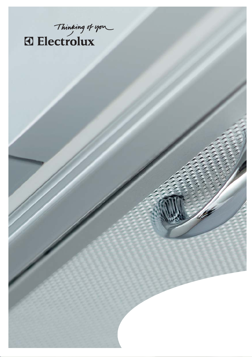
Wall drilling and bracket fi xing
Wall marking:
• Draw a vertical line on the supporting
wall up to the ceiling, or as high as
practical, at the centre of the area in
which the hood will be installed.
• Draw a horizontal line at 650 mm
above the hob.
• Place bracket 7.2.1 on the wall as
shown about 1-2 mm from the ceiling or upper limit aligning the centre
(notch) with the vertical reference line
• Mark the wall at the centres of the
holes in the bracket.
• Place bracket 7.2.1 on the wall as
shown at X mm below the fi rst brack-
et (X = height of the upper chimney
section supplied), aligning the centre
(notch) with the vertical line.
• Mark the wall at the centres of the
holes in the bracket.
• Mark a reference point as indicated
at 116 mm from the vertical reference
line and 325 mm above the horizontal
reference line.
• Repeat this operation on the other
side.
• Drill ø 8 mm holes at all the centre
points marked.
• Insert the wall plugs 11 in the holes.
• Fix the lower bracket 7.2.1 using the
12a screws (4,2 x 44,4) supplied.
• Fix the upper bracket 7.2.1 and the
air outlet connection support 7.3 to-
gether using the 2 screws 12a (4,2 x
44,4) supplied.
• Insert the two screws 12a (4,2 x 44,4)
supplied in the hood body fi xing holes,
leaving a gap of 5-6 mm between the
wall and the head of the screw.
EN
7.2.1
11
12a
650 min.
116
116
1÷2
X
315
325
Page 10
10 electrolux Installation
Hood body installation
• Before attaching the hood body,
tighten the two screws Vr located on
EN
the hood body mounting points.
• Hook the hood body onto the screws
12a.
• Fully tighten support screws 12a.
• Adjust screws Vr to level the hood
body
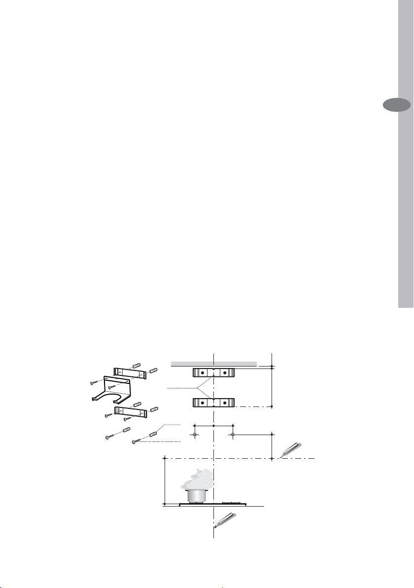
Connection in Ducting Version
When installing the ducting version,
connect the hood to the chimney using
either a fl exible or rigid pipe ø 150 or
120 mm, the choice of which is left to
the installer.
• To install a ø 120 mm air exhaust connection, insert the reducer fl ange 9 on
the hood body outlet.
• Fix the pipe in position using suffi cient
pipe clamps (not supplied).
• Remove charcoal fi lters, if present.
Connection in Recycling Version
• Put connection 15 into the connection support 7.3.
• Insert the connection extension pieces laterally 14.1 in connection 15.
• Make sure that the outlet of the extension pieces 14.1 is horizontally and
vertically aligned with the chimney
outlets.
• Connect the air outlet connection 15
to the hood body outlet using either
a fl exible or rigid pipe ø 150 mm, the
choice of which is left to the installer.
• Ensure that the activated charcoal
fi lters have been inserted.
Vr
12a
ø 120ø 150
9
14.1
15
ø 150
Page 11
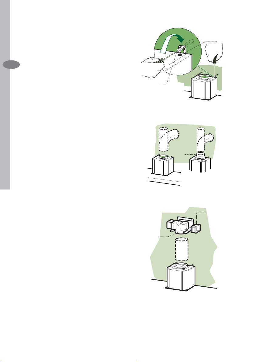
Electrical Connection
• Connect the hood to the mains
through a two-pole switch having a
contact gap of at least 3 mm.
• Remove the grease fi lters (see para-
graph Maintenance) being sure that
the connector of the feeding cable is
correctly inserted in the socket placed
on the side of the fan.
Chimney assembly
Upper Chimney
• Slightly widen the two sides of the upper Chimney and hook them behind
the brackets 7.2.1, making sure that
they are well seated.
• Secure the sides to the brackets using the 4 screws 12c (2,9 x 9,5) supplied.
• Make sure that the outlet of the extensions pieces is aligned with the chimney outlets.
Lower Chimney
• Slightly widen the two sides of the
Chimney and hook them between the
upper Chimney and the wall, making
sure that they are well seated.
• Fix the lower part laterally to the hood
body using the 2 screws 12c (2,9 x
9,5) supplied.
Installation electrolux 11
EN
7.2.1
12c
2.1
2
2.2
12c
Page 12

12 electrolux Use
USE
The hood can be switched on pushing directly onto the requested speed
S1 S2 S3
EN
LT4T1 T2 T3
Touch Basic Functions
control Dual functions
L When pressed it switches the lighting system on and off.
T1 When pressed the motor is stopped, regardless of the speed it is set to.
When pressed for 4 seconds it resets the fi lter alarm signal, with a
consequent indication of fl ashing led S1 or S2. This procedure can
be carried out only when the motor is stopped. Once the reset procedure is over the led S3 fl ashes twice.
T2 When pressed the motor is set to the fi rst speed. (Led S1 on)
T3 When pressed the motor is set to the second speed. (Led S2 on)
T4 When briefl y pressed the motor is set to the third speed. (Led S3 on)
When pressed for 2 seconds the motor is set to the intensive speed
timed to 10 minutes (Led S3 fl ashes) . After 10 minutes of intensive
speed the hood starts again at the speed it was previously set to. In
case the hood is set to the intensive speed directly from OFF-state
it will then start from the fi rst speed after 10 minutes of intensive
speed.
Alarm Signalling
Led Alarm type
S1 Metal grease fi lters saturation alarm.
When this led fl ashes it means that the metal grease fi lters need to be
washed. The alarm starts up after 100 working hours. (Reset; check the
paragraph “Metal fi lter”)
S2 Charcoal fi lter saturation alarm.
When this led fl ashes it means that the Charcoal fi lter has to be
replaced and metal grease fi lters washed. The alarm starts up after 200
working hours. (Activation and reset; check the paragraph “Charcoal
fi lter”).
Page 13

MAINTENANCE
Maintenance electrolux 13
Cleaning the Grill
• Remove the grill by pushing the handles. Pay attention that the grill will not
accidentaly fall down on the hob.
• The grill must never be washed in a
dishwasher.
• Clean the outside using a damp cloth
and neutral liquid detergent.
• Clean the inside as well using a damp
cloth and neutral detergent; do not
use wet cloths or sponges, or jets of
water; do not use abrasive substances.
• When the above operation has been
completed, hook the grill back to the
hood canopy and close it.
Cleaning of the Metal Cassette
Filter
Alarm reset
• Stop the motor.
• Press the T1 -touch control for at
least 4 seconds until the S3 -led
fl ashes twice.
Cleaning the fi lter
• Filter can be washed in the dish machine. It needs to be washed when
the S1 led starts to fl ash, or every 2
months or even more frequently in
case of particularly intensive use of
the hood.
• Remove the grill.
• Remove the fi lter pushing it towards
the back side of the unit and simultaneously pulling downwards
• Any kind of bending of the fi lter has to
be avoided when washing it. Before
fi tting it again into the hood make sure
that it is completely dry (The colour of
the fi lter surface may change through-
out the time but this has no infl uence
to the fi lter effi ciency).
• When fi tting the fi lter into the hood
pay attention that it is placed in correct position and that the handle faces
outwards.
• Place the grill in its seat.
EN
Page 14

14 electrolux Maintenance
Replacing the Charcoal Filter
This fi lter cannot be washed or regene-
rated, and must be replaced when the
EN
S2 led starts to fl ash, or at least once
every 4 months.
Enabling/Disabling the alarm signal
• In Recirculation Version Hoods, the
Filter saturation Alarm must be enabled at the time of installation or later.
• Switch off the lights and the motor.
• Disconnect the mains power supply
to the hood by removing the motor
unit power supply cable connector,
switching off the power supply at the
Mains or turning the Main switch off.
• Restore the connection by pressing
and holding T1.
• Release the touch control after 4
seconds, led S1 and S3 will fl ash to
confi rm as follows:
• 2 fl ashes – Charcoal Filter saturation
Alarm ACTIVATED
• 1 fl ash - Charcoal Filter saturation
Alarm DEACTIVATED
Reset the alarm signal
• Stop the motor.
• Press the T1 -touch control for at
least 4 seconds until the S3 -led
fl ashes twice.
Replace the Filter
• Remove the grill.
• Remove the metal grease fi lters.
• Remove the saturated charcoal fi lter,
turning the fasteners provided.
• Fit the new fi lter and fasten it its cor-
rect position.
• Put the metal grease fi lters in their
seats.
• Place the grill in its seat.
Light replacement
20 W halogen light.
• Find the cut side of the snap-on
cover ring by pressing gently toward
the centre of the spot light; it will be
released.
• Remove the snap-on cover and the
glass, being careful not to drop it.
• Remove the halogen lamp from the
lamp holder by pulling gently.
• Replace the lamp with a new one of
the same type, making sure that you
insert the two pins properly into the
housings on the lamp holder.
• Replace the glass and the snap-on
cover ring.
Page 15
Empfehlungen und Hinweise electrolux 15
EMPFEHLUNGEN UND HINWEISE
MONTAGE
• Das Gerät darf nur vom Fachpersonal
angeschlossen werden.
• Der Hersteller haftet nicht für Schäden, die
auf eine fehlerhafte und unsachgemäße
Montage zurückzuführen sind.
• Der minimale Sicherheitsabstand zwischen Kochmulde und Haube muss 650
mm betragen.
• Prüfen, ob die Netzspannung mit dem
Wert auf dem im Haubeninneren angebrachten Schild übereinstimmt.
• Bei Geräten der Klasse I ist sicherzustellen, dass die elektrische Anlage des
Wohnhauses über eine vorschriftsmäßige
Erdung verfügt.
• Das Anschlussrohr der Haube zur Luftaustrittsöffnung sollte möglicherweise einen
Durchmesser von 150 mm aufweisen.
Der Rohrverlauf muss so kurz wie möglich
sein.
• Die Haube darf an keine Entlüftungsschächte angeschlossen werden, in die
Verbrennungsgase (Heizkessel, Kamine
usw.) geleitet werden.
• Werden im Raum außer der Dunstabzugshaube andere, nicht elektrisch betriebene
(z.B. gasbetriebene) Geräte verwendet,
muss für eine ausreichende Belüftung
gesorgt werden. Sollte die Küche diesbezüglich nicht entsprechen, ist an einer
Aussenwand eine Öffnung anzubringen,
die Frischluftzufuhr gewährleistet.
BEDIENUNG
• Die Dunstabzugshaube ist ausschließlich
zum Einsatz im privaten Haushalt und zur
Beseitigung von Küchengerüchen vorgesehen.
• Bei unsachgemäßer Benutzung wird keine
Haftung übernommen.
Achtung! Große Flammen bei einge-
schalteter Haube niemals unbedeckt
lassen.
• Die Intensivität der Flamme ist so zu regulieren, dass sie den Topfboden nicht
überragt.
Achtung! Frittiergeräte müssen während des Gebrauchs stets beaufsichtigt werden: Überhitztes Öl kann sich
entzünden.
• Keine fl ambierten Speisen unter der Ab-
zugshaube zubereiten: Brandgefahr.
• Die Dunstabzugshaube darf von Kindern
oder Personen, die hinsichtlich der Bedienung nicht unterwiesen wurden, keinesfalls verwendet werden.
WARTUNG
• Bevor Wartungsarbeiten durchgeführt
werden, muss die Stromzufuhr zur Haube
unterbrochen werden, indem der Stecker
gezogen oder der Hauptschalter abgeschaltet wird.
• Bei der Filterwartung müssen die vom
Hersteller empfohlenen Zeiträume zum
Austauschen der Filter genauestens eingehalten werden.
• Zur Reinigung der Haubenfl ächen Wir
empfehlen ein feuchtes Tuch und ein mildes Flüssigreinigungsmittel.
• Bitte keine Reinigungsmittel mit Scheuermittel verwenden. Die Oberfl äche wird
damit verkratzt.
Das Symbol
seiner Verpackung weist darauf hin,
dass dieses Produkt nicht als normaler
Haushaltsabfall zu behandeln ist, sondern
an einem Sammelpunkt für das Recycling
von elektrischen und elektronischen Geräten
abgegeben werden muss. Durch Ihren
Beitrag zum korrekten Entsorgen dieses
Produkts schützen Sie die Umwelt und die
Gesundheit Ihrer Mitmenschen. Umwelt
und Gesundheit werden durch falsches
Entsorgen gefährdet. Weitere Informationen
über das Recycling dieses Produkts erhalten
Sie von Ihrem Rathaus, Ihrer Müllabfuhr oder
dem Geschäft, in dem Sie das Produkt
gekauft haben.
auf dem Produkt oder
DE
Page 16

16 electrolux Charakteristiken
CHARAKTERISTIKEN
Platzbedarf
DE
Page 17

Charakteristiken electrolux 17
Komponenten
Pos. St. Produktkomponenten
1 1 Haubenkörper mit Schaltern, Be-
leuchtung, Gebläsegruppe, Filter
2 1 Teleskopkamin bestehend aus:
2.1 1 oberer Kaminteil
2.2 1 unterer Kaminteil
9 1 Reduzierfl ansch ø 150-120 mm
14.1 2 Verlängerung Luftaustritt-
Anschlussstück
15 1 Luftaustritt-Anschlussstück
Pos. St. Montagekomponenten
7.2.1 2 Befestigungsbügel oberer Ka-
minteil
7.3 1 Bügel für Anschlusshalter
11 6 Dübel
12a 6 Schrauben 4,2 x 44,4
12c 6 Schrauben 2,9 x 9,5
St. Dokumentation
1 Bedienungsanleitung
15
14.1
7.3
9
2.1
2
2.2
1
12a
7.2.1 11
12c
11
12a
DE
Page 18

18 electrolux Montage
MONTAGE
Bohren der Befestigungslöcher
und Fixieren der Befestigungsbügel
DE
Nachstehende Linien an die Wand
zeichnen:
• Eine vertikale Linie bis zur Decke oder
oberen Begrenzung, und zwar in der
Mitte des Bereiches, in dem die Haube montiert werden soll;
• Eine horizontale Linie: mit einem minimalen Abstand von 650 mm zur
Kochfl äche.
• Einen Bügel 7.2.1 zirka 1-2 mm unter
der Decke oder oberen Begrenzung
an die Wand legen und seinen Mittelpunkt (Einschnitte) auf die vertikale
Bezugslinie ausrichten.
• Die Mitte der beiden Bügellöcher an
der Wand markieren.
• Den zweiten Bügel 7.2.1 an die Wand
legen, wobei ein Abstand X mm vom
oberen Bügel einzuhalten ist (X =
Höhe des jeweiligen oberen Kaminteils); den Mittelpunkt (Einschnitte) auf
die vertikale Bezugslinie ausrichten.
• Die Mitte der Bügellöcher an der
Wand markieren.
• Wie beschrieben einen Bezugspunkt
116 mm von der vertikalen Bezugslinie und 325 mm oberhalb der horizontalen Bezugslinie kennzeichnen.
• Gleichermaßen an der gegenüberliegenden Seite vorgehen.
• Mit einem Bohrer ø 8 mm die markierten Punkte bohren.
• Die Dübel 11 in die Bohrungen einfügen.
• Den unteren Bügel mit den mitgelieferten Schrauben 12a (4,2 x 44,4)
fi xieren.
• Den Bügel für Anschlusshalter 7.3 mit
den 2 mitgelieferten Schrauben 12a
(4,2 x 44,4) auf den oberen Bügel
7.2.1 befestigen
• 2 der mitgelieferten Schrauben 12a
(4,2 x 44,4) bei den Befestigungslöchern des Haubenkörpers einschrauben, wobei zwischen Wand und
Schraubenkopf ein Freiraum von 5-6
mm zu belassen ist.
7.2.1
11
12a
650 min.
116
116
1÷2
X
315
325
Page 19

Montage des Haubenkörpers
• Bevor der Haubenkörper eingehakt
wird, die 2 Schrauben Vr bei den
Haubenkörper-Anhakpunkten festziehen.
• Den Haubenkörper bei den Schrauben 12a einhängen.
• Die Halteschrauben 12a defi nitiv fest-
ziehen.
• Den Haubenkörper mit Hilfe der
Schrauben Vr ausrichten.
Anschluss in Abluftversion
Bei Abluftbetrieb kann die Haube vom
Installateur wahlweise mittels Rohr oder
Schlauch (ø 150 oder 120 mm) an die
Außenrohrleitung angeschlossen werden.
• Bei Verwendung eines Anschlussrohres ø 120 den Reduzierfl ansch 9 am
Haubenaustritt anbringen.
• Das Rohr mit geeigneten Rohrschellen fi xieren. Das hierzu erforderliche
Material wird nicht mitgeliefert.
• Eventuell vorhandene Aktivkohlefi lter
entnehmen.
Montage electrolux 19
Vr
DE
12a
ø 120ø 150
9
Anschluss in Umluftversion
• Den Anschluss 15 am Anschlusshalter 7.3 anbringen.
• Die Verlängerungen 14.1 beim Anschluss 15 seitlich einfügen.
• Überprüfen, ob die Verlängerungen
14.1 mit den entsprechenden Kaminstutzen sowohl horizontal wie auch
vertikal übereinstimmen.
• Vom Installateur wahlweise mittels
Rohr oder Schlauch (ø 150 mm), den
Anschluss 15 am Haubenaustritt anbringen.
• Kontrollieren, ob der Aktivkohle-Geruchsfi lter montiert ist.
14.1
15
ø 150
Page 20

20 electrolux Montage
Elektroanschluss
• Bei Anschluss der Haube an das
DE
Stromnetz muss ein zweipoliger
Schalter mit einem Öffnungsweg von
mindestens 3 mm zwischengeschaltet werden.
• Entfernen Sie die Fettfi lter (s. Ab-
schnitt „Wartung“) und versichern Sie
sich, daß die Kabelverbindung in die
Steckdose des Gebläses einwandfrei
eingesteckt wird.
Kaminmontage
Oberer Kaminteil
• Die beiden seitlichen Schenkel leicht
auseinanderbiegen, hinter den Bügeln
7.2.1 einhängen und bis zum Anschlag wieder schließen.
• Bei den Bügeln 7.2.1 mit Hilfe der 4
mitgelieferten Schrauben 12c fi xie-
ren.
• Überprüfen, ob die Verlängerungen
mit den entsprechenden Kaminstutzen übereinstimmen.
Unterer Kaminteil
• Die beiden seitlichen Schenkel des
Kaminteils leicht auseinanderbiegen,
zwischen dem oberen Kaminteil und
der Wand einhängen und bis zum
Anschlag wieder schließen.
• Den unteren Teil seitlich am Haubenkörper mit 2 der mitgelieferten
Schrauben 12c fi xieren.
7.2.1
12c
2.1
2
2.2
12c
Page 21

Bedienung electrolux 21
BEDIENUNG
Die Haube kann direkt auf die gewünschte Stufe eingeschaltet werden ohne daß
man vorher auf die Gebläsetaste 0/1 drückt.
S1 S2 S3
LT4T1 T2 T3
Taste Grundfunktion
Doppelfunktion
L Ein kurzer Tastendruck schaltet die Beleuchtungsanlage ein und aus.
Taste erloschen
T1 Schaltet den Motor unabhängig von der Gebläsestufe ab
Wird die Taste 4 Sekunden lang gedrückt, erfolgt die Rückstellung
des Filteralarms, der durch Blinken der Led S1 bzw. S2 angezeigt
wird. Dieses Verfahren kann nur bei abgeschaltetem Motor durchgeführt werden. Die Beendung dieses Verfahrens wird durch zweimaliges Blinken des Leds S3 angezeigt.
T2 Aktiviert den Motor mit der ersten Gebläsestufe. (Led S1 ein)
T3 Aktiviert den Motor mit der zweiten Gebläsestufe. (Led S2 ein)
T4 Aktiviert den Motor mit der dritten Gebläsestufe. (Led S3 ein)
Aktiviert den Motor mit der 10 Minuten dauernden Intensivstufe.
Nach Ablauf der 10 Minuten läuft das Gerät wieder mit der zuvor
eingestellten Sauggeschwindigkeit. Wird diese Funktion bei abgeschaltetem Gerät aktiviert, wird nach Ablauf der 10 Minuten auf die
erste Gebläsestufe übergegangen
DE
Signalisierung von Alarmen
Led Alarmentyp
S1 Sättigungsanzeige der Metallfettfi lter.
Signalisiert die Sättigung der Metallfettfi lter, die gewaschen werden müs-
sen. Der Alarm erfolgt nach 100 effektiven Arbeitsstunden der Haube.
S2 Sättigungsanzeige der Aktivkohle-Geruchsfi lter.
Signalisiert, falls dieser aktiviert wurde, dass die Filter auszutauschen
sind; die Metallfettfi lter müssen ebenfalls gewaschen werden. Die Sätti-
gungsanzeige des Aktivkohle-Geruchsfi lters erfolgt nach 200 effektiven
Arbeitsstunden der Haube. (Aktivierung siehe Abschn. Geruchsfi lter)
Page 22

22 electrolux Wartung
WARTUNG
Reinigung des Gitters
• Das Gitter aushacken, indem man
DE
die entsprechenden Drehknöpfen
betätigt. Bei dem Verfahren darauf
achten, dass das Gitter nicht herun-
terfällt.
• Das Gitter darf keinesfalls im Geschirrspüler gewaschen werden.
• Außen mit einem feuchten Lappen
und neutralem Flüssigreiniger säubern.
• Innen mit einem feuchten Lappen und
neutralem Reinigungsmittel säubern;
keine nassen Lappen oder Schwämme oder Wasserstrahl verwenden;
kein Scheuermittel verwenden.
• Am Ende die Platte wieder am Haubenkörper einhaken und schließen,
indem der Drehknopf in die dem
Öffnen entgegengesetzte Richtung
gedreht wird.
Reinigung selbsttragender Metallfettfi lter
Rückstellen der Sättigungsanzeige
• Den Gebläsemotor abschalten.
• Die Taste T1 mindestens 4 Sekunden
lang drücken, bis zum zweimaligen
Blinken des Leds S3.
Filterreinigung
• Der Filter kann auch im Geschirrspüler
gereinigt werden und sollte zirka alle
2 Monate - bzw. bei sehr intensivem
Einsatz auch häufi ger - gereinigt wer-
den.
• Das Gitter abnehmen.
• Den Filter entnehmen, indem er zur
Rückseite der Gruppe geschoben
und gleichzeitig nach unten gezogen
wird.
• Den Filter waschen, ohne ihn zu verbiegen, und vor dem erneuten Einbau
trocknen lassen. (die Farbe der Filteroberfl äche kann sich mit der Zeit
verändern, was aber die Wirksamkeit
keinesfalls beeinträchtigt.)
• Bei der Remontage darauf achten,
dass sich der Griff an der sichtbaren
Außenseite befi ndet.
• Das Gitter wieder einhacken.
Page 23

Wartung electrolux 23
Austauschen der AktivkohleFilter
Dieser Filter ist weder wasch- noch wiederverwendbar und ist auszutauschen,
wenn das Led S2 blinkt oder zumindest
alle 4 Monate. Die Sättigungsanzeige
erfolgt nur, wenn der Gebläsemotor
eingeschaltet ist.
Aktivierung/Deaktivierungder Sätti-
gungsanzeige
• Bei Hauben mit Umluftbetrieb erfolgt
die Aktivierung der Sättigungsanzeige
bei der Installation oder später.
• Die Beleuchtung und den Gebläsemotor abschalten.
• Die Haube vom Stromnetz trennen,
indem der Verbinder des Speisekabels der Motorgruppe gezogen oder
der zwischengeschaltete zweipolige
Schalter oder der Hauptschalter betätigt wird.
• Den Anschluss wieder herstellen,
während die Taste T1 gedrückt gehalten wird.
• Die Taste nach 4 Sekunden loslassen;
die Leds S1 und S3 leuchten als Bestätigung auf:
• 2-maliges Blinken – Sättigungsan-
zeige Aktivkohle-Geruchsfi lter AK-
TIVIERT
• 1-maliges Blinken – Sättigungs-
anzeige Aktivkohle-Geruchsfi lter
DEAKTIVIERT
Rückstellen der Sättigungsanzeige
• Den Gebläsemotor abschalten.
• Die Taste T1 mindestens 4 Sekunden
lang drücken, bis zum zweimaligen
Blinken des Leds S3.
Filterwechsel
• Das Gitter abnehmen.
• Die Metallfettfi lter entfernen.
• Den gesättigten Aktivkohle-Geruchsfi lter anhand der entsprechenden
Anhakvorrichtungen demontieren.
• Den neuen Filter montieren, indem er
in seinem Sitz eingehakt wird.
• Die Metallfettfi lter wieder montieren.
• Das Gitter wieder einhacken.
Auswechseln der Lampem
Halogenlampe 20 W
• Vor dem Auswechseln der Lampen,
die mittels Eindrücken befestigte
Glashalterung aus Metall durch Anheben der Zwinge entfernen und die
Halterung dabei mit einer Hand stützen.
• Die Lampe aus der Halterung nehmen.
• Die Lampe durch eine gleichwertige
ersetzen und bei der Remontage
darauf achten, daß die beiden Steckerstifte vorschriftsmäßig in die Lampenfassung eingeführt werden.
• Die Glashalterung wieder eindrücken.
DE
Page 24

24 electrolux Consejos y Sugerencias
CONSEJOS Y SUGERENCIAS
Installación
• El fabricante declina cualquier responsabilidad debida a los daños provoca-
ES
dos por una instalación incorrecta o
no conforme con las reglas.
• La distancia mínima de seguridad entre la encimera y la campana debe ser
de 650 mm.
• Comprobar que la tensión de red
corresponda a la indicada en la placa
situada en el interior de la campana.
• Para los aparatos de 1ª clase asegurarse de que la instalación eléctrica
doméstica posea una toma de tierra
efi caz.
• Conectar la campana a la salida del
aire de aspiración mediante un tubo
de 120mm de diámetro como mínimo. El recorrido del tubo debe ser lo
más corto posible.
• No conectar la campana a tubos de
descarga de humos producidos por
combustión (calderas, chimeneas,
etc.).
• En el caso que en la cocina se utilice
de manera silmultánea la campana
y otros aparatos no eléctricos (por
ejemplo aparatos de gas), debe existir
un sistema de ventilación sufi ciente
para todo el ambiente. Si la cocina
no posee un orifi cio que comunique
con el exterior, hay que realizarlo para
garantizar el recambio del aire.
Uso
• La campana ha sido concebida exclusivamente para un uso doméstico,
para eliminar los olores de la cocina.
No utilizarla de manera inadecuada.
• No dejar llamas libres de fuerte intensidad mientras la campana esté
funcionando.
• Regular siempre las llamas de manera
que éstas no sobresalgan lateralmente con respecto al fondo de las ollas.
• Controlar las freídoras durante su uso:
el aceite muy caliente se puede infl a-
mar.
• No preparar alimentos fl ambè debajo
de la campana de la cocina; peligro
de incendio
• La campana no debe ser utilizada por
niños o personas que no conozcan su
uso correcto.
Mantenimiento
• Antes de efectuar cualquier operación
de mantenimiento, desenchufar la
campana de la red eléctrica o apagar
el interruptor general.
• Efectuar un mantenimiento escrupuloso e inmediato de los fi ltros, según
los intervalos de tiempo aconsejados.
• Para limpiar las superfi cies de la cam-
pana es sufi ciente utilizar un trapo
mojado y detergente líquido neutro.
El símbolo en el producto o en su
embalaje indica que este producto no se
puede tratar como desperdicios normales
del hogar. Este producto se debe entregar al
punto de recolección de equipos eléctricos
y electrónicos para reciclaje. Al asegurarse
de que este producto se deseche
correctamente, usted ayudará a evitar
posibles consecuencias negativas para el
ambiente y la salud pública, lo cual podría
ocurrir si este producto no se manipula de
forma adecuada. Para obtener información
más detallada sobre el reciclaje de este
producto, póngase en contacto con la
administración de su ciudad, con su servicio
de desechos del hogar o con la tienda
donde compró el producto.
Page 25

CARACTERÍSTICAS
Dimensiones
Características electrolux 25
ES
Page 26

26 electrolux Características
Componentes
15
14.1
Ref. Cant. Componentes del Producto
ES
1 1 Cuerpo Campana dotado con:
mandos, luz, grupo de ventilaciòn, fi ltros
2 1 Chimenea telescópica formada
por:
2.1 1 Chimenea superior
2.2 1 Chimenea inferior
9 1 Brida de reducción ø 150-120
mm
14.1 2 Extensión del racor de salida del
aire
15 1 Racor de salida del aire
Ref. Cant. Componentes de Instalación
7.2.1 2 Bridas de fi jación chimenea supe-
rior
7.3 1 Bridas de fi jación Racor
11 6 Tacos ø 8
12a 6 Tornillos 4,2 x 44,4
12c 6 Tornillos 2,9 x 6,5
Cant. Documentación
1 Manual de instrucciones
7.3
9
2.1
2
2.2
1
12a
7.2.1 11
12c
11
12a
Page 27

INSTALACIÓN
Instalación electrolux 27
Taladrado pared y fi jación de las
bridas
Trazar en la pared:
• una línea vertical hasta el cielorraso
o límite superior, al centro de la zona
prevista para el montaje de la campana;
• una línea horizontal a 650 mm mín.
sobre el plano de cocción.
• Apoyar como se indica la brida 7.2.1
a 1-2 mm del cielo o del límite superior, alineando su centro (muescas)
con la línea vertical de referencia.
• Marcar los centros de los orificios de
la brida.
• Apoyar como se indica la brida 7.2.1
a X mm debajo de la primera brida (X
= altura chimenea superior en dotación), alineando su centro (muescas)
con la línea vertical de referencia.
• Marcar los centros de los orificios de
la brida.
• Marcar como se indica, un punto de
referencia a 116 mm de la línea vertical de referencia, y 325 mm sobre la
línea horizontal de referencia.
• Repetir esta operación en la parte
opuesta.
• Perforar ø 8 mm los puntos marcados.
• Introducir los tacos 11 en los orificios.
• Sujetar la brida inferior 7.2.1 usando
los tornillos 12a (4,2x44,4) en dotación.
• Sujetar la brida superior 7.2.1 a la
brida sujeción empalme 7.3 usando
los dos tornillos 12a (4,2x44,4) en
dotación.
• Atornillar 2 tornillos 12a (4,2x44,4) en
dotación en los agujeros de sujeción
del cuerpo de la campana, dejando
un espacio de 5-6 mm entre la pared
y la cabeza del tornillos.
1÷2
ES
7.2.1
11
12a
650 min.
116
116
X
315
325
Page 28

28 electrolux Instalación
Montaje del cuerpo de la campana
• Antes de enganchar el cuerpo de la
campana,apretar los 2 tornillos Vr
ES
situados en los puntos de enganche
del cuerpo de la campana .
• Enganchar el cuerpo de la campana
en los tornillos 12a predispuestos.
• Apretar definitivamente los tornillos
12a de soporte.
• Operar en los tornillos Vr para nivelar
el cuerpo de la campana.
Conexiones en versión aspirante
Para la instalación de la versión aspirante, conectar la campana al tubo de
salida mediante un tubo rígido o fl exible
de ø150 o 120 mm, a discreción del
instalador.
• Para la conexión con el tubo de ø120
mm, introducir la brida de reducción 9
en la salida del cuerpo de la campana.
• Fijar el tubo con abrazaderas adecuadas. Este material no se proporciona
en dotación.
• Quitar los filtros antiolor al carbón activo.
Vr
12a
ø 120ø 150
9
Conexión en versión fi ltrante
• Meter el racor 15 en la brida de sujeción 7.3.
• Introducir lateralmente las extensiones del racor 14.1 en el racor 15.
• Comprobar que la salida de las extensiones del racor 14.1 resulte en el
punto correspondiente a las bocas de
la chimenea tanto en horizontal como
en vertical.
• Conectar el racor 15 a la salida del
cuerpo de la campana mediante un
tubo rígido o flexible de Ø 150 mm,
cuya elección se deja al instalador.
• Comprobar la presencia del filtro antiolor de carbón activo.
14.1
15
ø 150
Page 29

Conexión eléctrica
• Conectar la campana a la red de
alimentación eléctrica instalando un
interruptor bipolar con apertura de los
contactos de 3 mm como mínimo.
• Quitar los Filtros antigrasa y asegurase de que el conector del Cable de
acometida esté colocado correctamente en el enchufe del Aspirador.
Montaje de la chimenea
Instalación electrolux 29
ES
Chimenea superior
• Ensanchar ligeramente las dos faldas
laterales, engancharlas detrás de las
bridas 7.2.1 cerrarlas hasta el tope.
• Fijar a los lados de las bridas con los 4
tornillos 12c (2,9 x 9,5) en dotación.
• Asegurarse que la salida de las extensiones del racor coincida con las
boquillas de la chimenea.
Chimenea inferior
• Ensanchar ligeramente las dos faldas
laterales de la chimenea, engancharlas entre la chimenea superior y la
pared y cerrarlas hasta el tope.
• Fijar lateralmente la parte inferior en
el cuerpo de la campana, con los 2
tornillos 12c (2,9 x 9,5) en dotación.
7.2.1
12c
2.1
2
2.2
12c
Page 30

30 electrolux Uso
USO
La campana puede ser encendida directamente a la velocidad deseada, apretándo
la tecla correpondiente
S1 S2 S3
ES
LT4T1 T2 T3
Tecla Función base
Doble Función
L Apretado enciende y apaga la instalación de iluminación.
T1 Apaga el motor desde cualquier velocidad programada
Apretada durante 4 segundos restablece la señal de alarma fi ltros
señalada por el led S1 o S2. Este procedimiento se puede realizar
sólo con el motor apagado.Un doble relampagueo del led S3 señala
el fi nal del procedimiento.
T2 Activa el motor a la primera velocidad. (Led S1 encendido)
T3 Activa el motor a la segunda velocidad. (Led S2 encendido)
T4 Activa el motor a la tercera velocidad. (Led S3 encendido)
Apretado durante 2 segundos pone en marcha el motor a la velocidad intensiva durante 10 minutos (Led S3 relampaguea). Al cabo
de los 10 minutos el aparato vuelve a la velocidad anteriormente
programada. En el caso de encendido del aparato, cundo pasen los
10 minutos el sistema vuelve a la primera velocidad.
Señalación Alarmas
Led Tipo de alarma
S1 Alarma saturación fi ltro metálico
Señala la saturación del Filtro Antigrasa Metálico y la necesidad de la-
varlo. La alarma entra en función tras 100 horas de trabajo efectivo de
la Campana. (Reset ver párrafo Filtro metálico)
S2 Alarma saturación fi ltro al carbón
Señala, cuando se activa, la saturación del Filtro Antiolor al Carbón Ac-
tivo, que debe ser sustituido; es necesario lavar también el Filtro Antigrasa Metálico. La alarma de saturación del Filtro Antiolor al Carbón Activo entra en función tras 200 horas de trabajo efectivo de la Campana.
(Activación y reset ver párrafo Filtro Antiolor)
Page 31

MANTENIMIENTO
Mantenimiento electrolux 31
Limpieza de la rejilla
• Desenganchar la rejilla obrando en las
manillas, teniendo cuidado de sujetarla mientras se abre para evitar que se
nos caiga sobre el plano de cocción.
• La rejilla no se puede lavar absolutamente en el lavavajillas.
• Limpiarla externamente con un paño
húmedo y detergente líquido neutro.
• Limpiarla internamente utilizando un
paño húmedo y detergente neutro;
no utilizar paños o esponjas mojadas
ni chorros de agua; no utilizar sustancias abrasivas.
• Una vez finalizada la operación enganchar la rejilla en el cuerpo de la
campana y cerrarla.
Limpieza del fi ltro antigrasa
metálico autoportante
Reset de la señal de alarma
• Apagar el Motor de aspiración.
• Apretar la tecla T1 durante 4 segun-
dos, hasta que el led S3 relampaguee
dos veces.
Limpieza Filtro
• El filtro es lavable en lavavajillas, y hay
que lavarlo cuando el led S1 relampaguea, o aproximadamente cada 2
meses de uso de la campana o más
frequentemente si su empleo es particularmente intenso.
• Quitar la rejilla.
• Sacar el Filtro, empujándolo hacia la
parte posterior del grupo y tirando al
mismo tiempo hacia abajo.
• Lavar el Filtro evitando doblarlo, y
dejarlo secar antes de reensamblarlo.
(Un eventual cambio del color de la
superficie del filtro, que podría producirse con el paso del tiempo, no
perjudica absolutamente la eficiencia
del mismo.)
• Volver a colocarlo teniendo cuidado
de que la manilla quede hacia la parte
visible externa.
• Volver a colocar la rejilla.
ES
Page 32

32 electrolux Mantenimiento
Sustitución fi ltro al carbón
No es lavable y no es regenerable, hay
que sustituirlo cuando el led S2 relam-
ES
paguea o por lo menos cada 4 meses.
La señal de alarma sólo se activa cuando el Motor de aspiración está en funcionamiento.
Activación/Desactivación de la señal de alarma
• En las Campanas en Versión Filtrante,
la señal de Alarma saturación Filtro
debe ser activada en el momento de
la instalación o sucesivamente.
• Apagar las Luces y el Motor de aspiración.
• Desconectar la Campana desenchufándola o quitando los plomos.
• Restablecer la conexión teniendo
apretada la tecla T1.
• Soltar la tecla al cabo de de 4 segundos, los leds S1 y S3 relampaguean
para confirmar :
• 2 relampagueos - Alarma satura-
ción Filtro al Carbón ACTIVADO
• 1 relampagueo - Alarma saturación
Filtro al Carbón DESACTIVADO
Reset de la señal de alarma
• Apagar el Motor de aspiración.
• Apretar la tecla T1 durante 4 segun-
dos, hasta que el led S3 relampaguee
dos veces.
Sustitución Filtro
• Quitar la rejilla.
• Sacar el Filtro antigrasa metálico.
• Quitar el Filtro antiolor al Carbón acti-
vo saturado, operando en los enganches debidos.
• Montar el Filtro nuevo enganchándolo
en su sede.
• Reensamblar el Filtro antigrasa metá-
lico.
• Volver a colocar la rejilla.
Sustitución Lámparas
Lámparas halógenas de 20 W
• Localizar el corte de interrupción del
anillo que sujeta el cristal, ejerciéndo
una ligera presión hacia el centro de
la lámpara, se desbloqueará.
• Quitar el anillo que sujeta el cristal y el
cristal teniendo cuidado de que no se
caiga.
• Sacar la lámpara halógena del portalámparas.
• Sustituirla con una nueva de características idénticas, teniendo cuidado
de colocar correctamente los dos
pernos en la sede del portalámparas.
• Volver a colocar el cristal y el anillo
que sujeta el cristal a presión.
Page 33

CONSELHOS E SUGESTÕES
Conselhos e Sugestões electrolux 33
INSTALAÇÃO
• O fabricante declina toda e qualquer responsabilidade pelos danos decorrentes
de uma instalação não correcta ou feita
não em conformidade com as normas da
boa técnica.
• A distância mínima de segurança entre a
placa de cozedura e o exaustor deve ser
de 650 mm.
• Verifi que se a tensão da rede coincide
com a indicada na placa de características aplicada no interior do exaustor.
• Para os aparelhos de Classe I
se de que a instalação doméstica garanta
uma descarga correcta à terra.
• Ligue o exaustor à saída do ar aspirado
utilizando um tubo de diâmetro igual ou
superior a 120 mm. O percurso do tubo
deve ser o mais breve possível.
• Não ligue o exaustor a tubos de descarga
de fumaça produzida porcombustão (caldeiras, lareiras, etc...).
• Caso no mesmo local sejam utilizados
quer o exaustor, quer aparelhos não
accionados pela corrente eléctrica (por
exemplo, aparelhos alimentados a gás),
será preciso providenciar uma ventilação
sufi ciente do aposento. Se a cozinha não
possuir uma abertura que comunique
com o exterior, providencie a sua realização para garantir a entrada de ar limpo.
USO
• O exaustor foi projectado para ser utilizado exclusivamente em ambientes
domésticos, sendo a sua fi nalidade a de
reduzir os odores de cozedura. Não utilize
o aparelho de maneira imprópria.
• As chamas de forte intensidade não devem fi car descobertas enquanto o exaus-
tor estiver a funcionar.
• Regule sempre as chamas de maneira
que não sobressaiam do fundo das panelas.
a
, certifi que-
• Mantenha as frigideiras sob controlo
durante o uso: o óleo excessivamente
aquecido pode infl amar-se.
• No prepare alimentos fl amejados sob o
exaustor. Perigo de incêndio!
• O exaustor não deve ser utilizado por
crianças ou por pessoas não devidamente habilitadas à sua utilização correcta.
MANUTENÇÃO
• Antes de efectuar qualquer operação de
manutenção, desligue o exaustor tirando
a fi cha da tomada de corrente ou desli-
gando o interruptor geral.
• Faça uma manutenção atenta e rápida
dos fi ltros, respeitando os intervalos
aconselhados.
• Para limpar as superfícies do exaustor, é
sufi ciente utilizar um pano húmido e de-
tergente líquido neutro.
O símbolo
gem indica que este produto não pode ser
tratado como lixo doméstico. Em vez disso,
deve ser entregue ao centro de recolha selectiva para a reciclagem de equipamento
eléctrico e electrónico. Ao garantir uma eliminação adequada deste produto, irá ajudar
a evitar eventuais consequências negativas
para o meio ambiente e para a saúde pública, que, de outra forma, poderiam ser
provocadas por um tratamento incorrecto
do produto. Para obter informações mais
pormenorizadas sobre a reciclagem deste
produto, contacte os serviços municipalizados locais, o centro de recolha selectiva da
sua área de residência ou o estabelecimento
onde adquiriu o produto.
no produto ou na embala-
PT
Page 34

34 electrolux Características
CARACTERÍSTICAS
Dimensões
PT
Page 35

Características electrolux 35
Componentes
Ref. Qtd Componentes do produto
1 1 Corpo do exaustor equipado
com: Comandos, iluminação,
grupo do ventilador e fi ltros
2 1 Chaminé telescópica formada
por:
2.1 1 Chaminé Superior
2.2 1 Chaminé Inferior
9 1 Flange de redução ø 150-120
mm
14.1 2 Extensão de conexão da saída
de ar
15 1 Conexão da saída de ar
Réf. Qtd Componentes de instalação
7.2.1 2 Suportes de fi xação da chaminé
superior
7.3 1 Suportes de fi xação de Conexão
11 6 Buchas
12a 6 Parafusos 4,2 x 44,4
12c 6 Parafusos 2,9 x 9,5
Qtd Documentação
1 Manual de Instruções
15
14.1
7.3
9
2.1
2
2.2
1
12a
7.2.1 11
12c
11
12a
PT
Page 36

36 electrolux Instalação
INSTALAÇÃO
Perfuração da parede e fi xação
dos suportes
Marque na parede:
PT
• uma linha vertical que vá até ao tecto
ou ao limite superior, ao centro da zona
destinada à montagem do exaustor;
• uma linha horizontal a, pelo menos,
650 mm de distância acima da placa
do fogão.
• Apoie o suporte 7.2.1 como indicado,
a 1-2 mm de distância do tecto ou
do limite superior, alinhando o centro
deste (entalhes) sobre a linha de referência vertical.
• Marque os centros dos furos do su-
porte.
• Apoie o suporte 7.2.1 como indicado,
X mm abaixo do primeiro suporte (X
= altura da chaminé superior fornecida de série), alinhando o seu centro
(entalhes) sobre a linha de referência
vertical.
• Marque os centros dos furos do suporte.
• Marque, com indicado, um ponto de
referência a 116 mm de distância da
linha de referência vertical, e 325 mm
acima da linha de referência horizontal.
• Repita esta operação do lado oposto.
• Fure os pontos marcados com ø 8
mm.
• Introduza as buchas 11 nos furos.
• Fixe o Suporte inferior 7.2.1 utilizando
os Parafusos 12a (4,2 x 44,4 ) fornecidos com o aparelho.
• Fixe juntos os Suportes superior, 7.2.1,
e de Sustentação da conexão, 7.3, utilizando os dois
• Aperte dois dos parafusos 12a (4,2 x
44,4) que acompanham o aparelho,
nos orifícios de fi xação da estrutura
do exaustor, deixando um espaço de
5-6 mm entre a parede e a cabeça do
parafuso.
1÷2
7.2.1
11
12a
650 min.
116
116
X
315
325
Page 37

Montagem do corpo do extractor
• Antes de fi xar o corpo do extractor,
aperte os dois parafusos Vr situados
nos pontos de montagem do corpo do
extractor.
• Pendure o corpo do extractor nos dois
parafusos 12a.
• Aperte totalmente os parafusos do
suporte 12a.
• Ajuste os parafusos Vr para nivelar o
corpo do extractor.
Ligações na versão aspirante
Para a instalação na Versão Aspirante, ligue o exaustor ao tubo de saída
utilizando um tubo rígido ou fl exível de
ø150 ou 120 mm; esta escolha deve ser
feita pelo instalador.
• Para a ligação com um tubo de ø120
mm, instale a fl ange de redução 9 na
saída do corpo do exaustor.
• Fixe o tubo com braçadeiras de aperto
adequadas. O material necessário não
é fornecido com o aparelho.
• Tire os fi ltros anti-odor de carvão acti-
vo, se presentes..
Instalação electrolux 37
Vr
PT
12a
ø 120ø 150
9
Ligação na versão com recirculação
• Coloque a ligação 15 no suporte da
ligação 7.3.
• Introduza lateralmente as peças de
extensão da ligação 14.1 na ligação 15.
• Certifi que-se de que a saída das pe-
ças da extensão 14.1 está alinhada horizontal e verticalmente com as saídas
da chaminé.
• Ligue a ligação da saída de ar 15 à
saída do corpo do extractor utilizando
um tubo fl exível ou um tubo rígido de
ø 150 mm, sendo a escolha deixada
ao critério do responsável pela instalação.
• Certifi que-se de que os fi ltros de car-
vão activado foram instalados.
14.1
15
ø 150
Page 38

38 electrolux Instalação
Ligação eléctrica
• Ligue o extractor à alimentação uti-
PT
lizando um interruptor de dois pólos
com uma folga de contacto de pelo
menos 3 mm.
• Retire os fi ltros contra gordura (ver
parágrafo da Manutenção) certifi can-
do-se de que o conector do cabo de
alimentação está correctamente instalado na tomada existente do lado do
ventilador.
Montagem da chaminé
Chaminé de exaustão superior
• Alargue ligeiramente os dois lados da
chaminé superior e pendure-os por
trás dos suportes 7.2.1, certifi cando-
se de que fi cam correctamente assen-
tes.
• Fixe os lados nos suportes utilizando
os 4 parafusos 12c (2,9 x 9,5) fornecidos.
• Certifi que-se de que a saída das pe-
ças das extensões fi ca alinhada com
as saídas da chaminé.
Chaminé de exaustão inferior
• Alargue ligeiramente os dois lados da
chaminé e pendure-os entre a chaminé superior e a parede, certifi cando-se
de que fi cam correctamente assentes.
• Fixe a parte inferior lateralmente ao
corpo do extractor utilizando os 2 parafusos 12c (2,9 x 9,5) fornecidos.
7.2.1
12c
2.1
2
2.2
12c
Page 39

Utilização electrolux 39
UTILIZAÇÃO
O exaustor pode ser aceso directamente na velocidade desejada, premindo a tecla
correspondente
S1 S2 S3
LT4T1 T2 T3
Tecla Função de base
Dupla função
L Premido, liga e desliga o sistema de iluminação.
T1 Desliga o motor, seja qual for a velocidade em que estiver a funcionar
Premido durante 4 segundos, faz o reset da sinalização de alarme
dos fi ltros, que consiste no piscar dos leds S1 ou S2. Este processo
só é executável com o motor desligado. O fi m do processo é sinali-
zado pelo led S3, que pisca duas vezes seguidas.
T2 Põe o motor a funcionar com velocidade I. (Led S1 aceso)
T3 Põe o motor a funcionar com velocidade II. (Led S2 aceso)
T4 Põe o motor a funcionar com velocidade III. (Led S3 aceso)
Premido durante 2 segundos, põe o motor a funcionar com velocidade intensa, durante o tempo limite de 10 minutos (o led S3 pisca).
Ao fi m dos 10 minutos, o aparelho regressará automaticamente à
velocidade com que funcionava anteriormente. Em caso de activação, partindo da situação de aparelho desligado, o sistema, decorridos os 10 minutos da função, regressará à velocidade I.
Sinalizações dos alarmes
Led Tipo de alarme
S1 Alarme por saturação dos fi ltros metálicos
Sinaliza o alarme de saturação dos fi ltros de metal antigordura e a
necessidade de os lavar. O alarme dispara ao fi m de 100 horas de fun-
cionamento efectivo do exaustor. (Para desligar ver parág. Filtros metálicos)
S2 Alarme por saturação dos fi ltros de carvão
Sinaliza que está activado o alarme de saturação do fi ltro anti-odores
de carvão activo e que é, portanto, necessário substituí-lo. Devem lavar-se também, nesta altura, os fi ltros de metal antigordura. O alarme
de saturação do fi ltro anti-odores de carvão activo dispara ao fi m de
200 horas de funcionamento efectivo do exaustor. (Para activação e
desactivação, ver parág. Filtro anti-odores)
PT
Page 40

40 electrolux Manutenção
MANUTENÇÃO
Limpeza da grade
• Soltar a grade dos respectivos ele-
PT
mentos de fi xação, operando nos ma-
nípulos próprios, tendo o cuidado de a
segurar enquanto se abre, para evitar
que caia sobre a placa do fogão.
• A grade não pode, de modo nenhum,
ser lavada na máquina de lavar louça.
• Limpe a parte de fora com um pano
húmido e detergente líquido neutro.
• Limpe-a também interiormente, utilizando um pano húmido e detergente
neutro. Não utilize panos ou esponjas
molhados nem jactos de água. Não
use substâncias abrasivas.
• Concluído o trabalho, prenda de novo
a grade na estrutura do exaustor e feche-a.
Limpeza do fi ltro metálico anti-
gordura
Como apagar o sinal de alarme
• Desligue o motor de aspiração.
• Prima a tecla T1 durante, pelo menos,
4 segundos, até o led S3 piscar duas
vezes seguidas, a confi rmar.
Limpeza do fi ltro
• Os fi ltros também podem ser lavados
na máquina de lavar louça e precisam
de lavagem quando o led S1 começa
a piscar ou, pelo menos, cerca de 2
em 2 meses de uso. No caso de uma
utilização bastante intensa é preciso
lavá-los com maior frequência.
• Remova a grade.
• Retire o fi ltro, empurrando-o em di-
recção à parte posterior do grupo, ao
mesmo tempo que o puxa para baixo.
• Lave os fi ltros, evitando dobrá-los, e
deixe-os secar antes de os reinstalar.
(A eventual alteração de cor da superfície do fi ltro que, com o tempo, se po-
derá verifi car, não prejudica de maneira
nenhuma a sua efi cácia.)
• Reinstale-os, tendo o cuidado de
manter a pega virada para a parte visível exterior.
• Coloque de novo a grade na sua posição original.
Page 41

Manutenção electrolux 41
Substituição do fi ltro de carvão
Não pode ser lavado e não é regenerável. Deve ser substituído quando o led
S2 começa a piscar ou, pelo menos, de
4 em 4 meses. A sinalização de alarme
só se verifi ca quando se acciona o mo-
tor de aspiração.
Activação/desactivação do sinal de
alarme
• Nos exaustores na versão fi ltrante, a
sinalização do alarme por saturação
dos fi ltros tem de ser activada na
altura de instalação do exaustor, ou
posteriormente.
• Desligue as luzes e o motor de exaustão.
• Desligue a alimentação de rede do
exaustor, removendo o conector do
cabo de alimentação do grupo do motor, ou accionando o interruptor bipolar
colocado na alimentação de rede, ou
desligando o interruptor geral.
• Repor a ligação, mantendo premida a
tecla T1.
• Soltar a tecla decorridos 4 segundos.
Os leds S1 e S3 piscam, para confi r-
mar:
• 2 piscadelas seguidas - Alarme de
saturação do fi ltro de carvão ACTI-
VADO
• 1 piscadela única - Alarme de satu-
ração do fi ltro de carvão DESACTI-
VADO
Como apagar o sinal de alarme
• Desligue o motor de aspiração.
• Prima a tecla T1 durante, pelo menos,
4 segundos, até o led S3 piscar duas
vezes seguidas, a confi rmar.
Substituição do fi ltro
• Remova a grade.
• Desmonte os fi ltros metálicos antigor-
dura.
• Remova o fi ltro anti-odores de carvão
activo saturado, manobrando os respectivos engates.
• Monte o fi ltro novo, prendendo-o no
respectivo encaixe.
• Monte de novo os fi ltros metálicos an-
tigordura.
• Coloque de novo a grade na sua posição original.
Substituição das lâmpadas
Lâmpadas halógenas de 20 W
• Localize o corte existente no anel de
fi xação do vidro. Exercendo uma ligeira pressão em direcção ao centro do
foco, ele solta-se.
• Retire o componente de fi xação do
vidro, evitando que caia.
• Desmonte a lâmpada halógena do
casquilho.
• Substitua-a por uma nova com as
mesmas características, tendo o cuidado de introduzir correctamente os
dois pinos na sede do casquilho.
• Monte de novo o vidro e o elemento de
fi xação respectivo, à pressão.
PT
Page 42

42 electrolux TAVSIYELER VE ÖNERILER
TAVSIYELER VE ÖNERILER
MONTAJ
• Yalnιş veya eksik montajdan doğan herhangi
TR
bir zararιn sorumluluğu üreticiye ait değildir.
• Besleme voltajιnιn, davlumbaz içerisine
yerleştirilen bilgi etiketinde belirtilenle aynι
olup olmadιğιnι kontrol edin.
• Sιnιf I elektrikli aletleri için, güç kaynağιnιn
yeterli topraklamayι sağlayιp sağlamadιğιnι
kontrol edin. Minimum 120 mm çapιnda
bir boru yoluyla davlumbazι çιkιş bacasιna
bağlayιn. Baca bağlantιsι mümkün olduğunca kιsa olmalιdιr.
• Davlumbaz borusunu yanιcι duman taşιyan
baca deliğine (buhar kazanι, şömine, vb.)
bağlamayιn.
• Davlumbazι
n elektrikle çalιşmayan aletlerle
(örneğin; gazlι cihazlar) bağιntιlι olarak
kullanιlmamasι halinde çιkιş gazιnιn geri
tepmesini önlemek amacιyla odada yeterli
bir havalandιrma sağlanmalιdιr. Temiz hava
girişini temin etmek için mutfakta doğrudan
dιşarιya açιlan bir açιklιk bulunmalιdιr.
KULLANIM
• Davlumbaz mutfaktaki kokularιn
emilmesi amacιyla evlerde kullanιm için
tasarlanmιştιr.Ticari ve endüstriyel amaçlar
için kullanmayιnιz.
• Davlumbazι tasarlandιğι amaçlarιn dιşιnda
kesinlikle kullanmayιnιz.
• Davlumbaz çalιşιrken altιnda kesinlikle
yüksek çιplak ateş bιrakmayιn.
• Alev yoğunluğunu doğrudan tencerenin
altιnda kalacak şekilde ayarlayιn, kenarlarιnι
sarmadιğιndan emin olun.
• Yağda kιzartma tavalarιnι kullanιrken sürekli
olarak takip edin: fazla ιsιnan yağ tutuşabilir.
• Kapağın altında kıvılcımdan kaçının, yangın
riski
• Davlumbaz çocuklar veya doğru kullanιm
konusunda bilgisi olmayan kişiler tarafιndan
kullanιlmamalιdιr.
BAKIM
• Herhangi bir bakιm işlemini gerçekleştirmeden
önce davlumbazι kapatιn veya fi şini çιkarιn.
• Filtreleri belirtilen zamanlarda temizleyin ve /
veya değiştirin.
• Cihazι nemli bir bez ve nötr bir sιvι deterjan
kullanarak temizleyin.
Ürün veya paketi üzerindeki sembolü, bu
ürünün normal bir evsel atık olarak görülmemesi
ve bu tip elektrikli veya elektronik cihazların atıldığı
dönüşümlü toplama noktalarına terkedilmesi
gerektiğine işaret eder. Bu ürünü gerektiği gibi
elimine etme kurallarına uyarsanız çevre ve insan
sağlığı üzerindeki olumsuz etkilerini bertaraf etmeye
katkı sağlamış olursunuz. Bu ürünün geri dönüşüm
koşulları hakkında daha ayrıntılı bilgi için hudutları
içinde bulunduğunuz belediyenin ilgili diaresine, atık
yoketme servisine veya ürünün satıcısına danışınız.
Page 43

ÖZELLIKLER
Boyutlar
ÖZELLIKLER electrolux 43
TR
Page 44

44 electrolux ÖZELLIKLER
Parçalar
Ref. Adet Ürünün parçaları
TR
1 1 Şunlardan oluşan davlumbaz gövdesi:
Kumandalar, Lamba, Fan grubu,
Filtreler
2 1 Şunlardan oluşan teleskopik baca:
2.1 1 Üst baca
2.2 1 Alt baca
9 1 Redüksiyon Flanşı ø 150-120 mm
14.1 2 Hava Çıkışı Uzatma Rakoru
15 1 Hava Çıkışı Rakoru
Ref. Adet Montaj Parçaları
7.2.1 2 Üst Baca Tesbit Braketleri
7.3 1 Rakor Destek Braketi
11 6 Dübeller
12a 6 Vidalar 4,2 x 44,4
12c 6 Vidalar 2,9 x 9,5
Adet Belgeler
1 Talimat Kılavuzu
15
14.1
7.3
9
2.1
2
2.2
1
12a
7.2.1 11
12c
11
12a
Page 45

MONTAJ
MONTAJ electrolux 45
Duvarın Delinmesi ve Braketlerin
Sabitlenmesi
Duvara şunları çiziniz:
• Tavana yada üst sınıra kadar uzunan Dikey
bir çizgi: Davlumbazın monte edileceği yerin
tam merkezinden geçmelidir;
• Tezgâh (setüstü ocak) yüzeyinden 650 mm
mesafeden geçen bir Yatay çizgi.
• Gösterildiği gibi Braketi 7.2.1 tavandan 1-2
mesafeye dayayınız ve bunun merkezini
(çentik) Dikey referans çizgisine hizalayınız.
• Braketin deliklerinin ortasından işaret
koyunuz.
• Gösterildiği gibi Braketi 7.2.1 ilk braketin
altına ve bundan X mesafeye dayayınız (X
= Üst Bacanın boyu) ve bunun merkezini
(çentik) Dikey referans çizgisine hizalayınız.
• Braketin deliklerinin ortasından işaret
koyunuz.
• Gösterildiği gibi Dikey referans çizgisinden
116 mm mesafeye, Yatay referans çizgisinin
de 325 mm üzerine gelecek şekilde bir
referans deliği işaretleyiniz.
• Bu işlemi diğer taraftan da tekrar ediniz.
• İşaretlenen yerlere ø 8 mm çapında delikler
açınız.
• Dübelleri (11) deliklere yerleştiriniz.
• Cihaz donanımında verilen vidaları 12a
(4,2 x 44,4 ) kullanarak alt Braketi 7.2.1
sabitleyiniz.
• Üs Braket 7.2.1 ile rakor destek Braketini
7.3 cihaz donanımında verilen 2 adet
vidayı 12a (4,2 x 44,4 ) kullanarak birlikte
sabitleyiniz.
• Davlumbaz gövdesinin sabitlenmesi için,
açılan deliklere donanımdaki 2 adet vidayı
12a (4,2 x 44,4) takıp, sıkınız ve vidanın
kafası ile duvar arasında 5-6 mm’lik bir
mesajfe bırakınız.
1÷2
TR
7.2.1
11
12a
650 min.
116
116
X
315
325
Page 46

46 electrolux MONTAJ
Davlumbaz Gövdesi Montajı
• Davlumbaz Gövdesini kancalara
takmadadan önce gövde üzerindeki
kancalama noktalarında bulunan 2 adet
TR
vidayı Vr sıkınız.
• Davlumbaz Gövdesini vidalara 12a takınız.
• Destek vidalarını 12a nihai olarak sıkınız.
• Vr vidalarına müdahale ederek Davlumbaz
Gövdesi seviyesini hizalayınız.
Emme ağzı versiyonunda
bağlantılar
Aspiratörlü modelin montajı için, davlumbaz,
montörün seçeceği 150 yada 120 mm çapında
sert veya esnek bir boru ile çıkış kanalına
bağlanmalıdır.
• ø120 mm çapında boru ile bağlantı için,
redüksiyon fl anşını (9) davlumbaz gövdesi
çıkışına yerleştiriniz.
• Boruyu uygun kelepçelerle sıkarak
sabitleyiniz. Bu malzeme davlumbaz
donanımıyla birlikte verilmemiştir.
• Varsa aktif karbonlu koku alma fi ltrelerini
çıkarınız.
Vr
12a
ø 120ø 150
9
Filtre versiyonunda bağlantılar
• Rakoru 15 Destek Braketine 7.3. geçiriniz.
• Rakor Uzantılarını 14.1 diğer Rakora takınız
15.
• Rakor Uzantıları çıkışının 14.1 hem dikey
hem yatay planda Baca ağızlarına denk
gelmesine dikkat ediniz.
• Rakoru 15 montörün seçeceği sert yada
esnek 150 mm çapında bir boru ile
Davlumbaz Gövdesi Çıkışına bağlayınız.
• Aktif Karbonlu Koku Filtresinin mevcut
olduğundan emin olunuz.
14.1
15
ø 150
Page 47

Elektrik bağlantılar
• Davlumbazı şebeke cereyanına bağlarken
aray temas aralığı en az 3 mm olan çift
kutuplu bir elektrik anahtarı koyunuz.
• Yağ tutucu fi ltreleri çıkarınız (bakınız
“Bakım” paragrafı) ve besleme kablosu
soketinin aspiratör prizine iyice takılmış
olduğundan emin olunuz.
Bacanın Montajı
MONTAJ electrolux 47
TR
Üst Baca
• İki yan kenarı hafi fçe açınız, bunları
braketlerin 7.2.1 arkasına geçiriniz ve tam
dayanana kadar tekrar kapatınız.
• Cihaz donanımında verilen 4 adet vidayla
12c (2,9 x 9,5) yan tarafl arından braketlere
sabitleyiniz.
• Rakor uzantılarının çıkışının baca ağızlarına
denk gelmesine dikkat ediniz.
Alt Baca
• Bacanın iki yan kenarını hafi fçe açınız, Üst
baca ile duvar arasına geçirip tam dayanana
kadar kapatınız.
• Cihaz donanımında verilen 2 adet vidayla
12c (2,9 x 9,5) alt tarafını davlumbaz
gövdesine sabitleyiniz.
7.2.1
12c
2.1
2
2.2
12c
Page 48

48 electrolux KULLANIM
KULLANIM
Davlumbaz ilgili tuşa basılarak direk olarak istenilen hızda çalıştırılabilir.
S1 S2 S3
TR
LT4T1 T2 T3
Tuş Temel fonksiyon
Çift Fonksiyon
L Kısa bir süre basılı tutulmak suretiyle aydınlatma tertibatını açar ve kapatır.
T1 Ayarlanmış olan herhangi bir hızda motoru kapatmaktadır.
4 saniye boyunca basılı tutulması halinde fi ltre alarm sinyali S1 veya S2 led’inin
yanıp sönmesiyle eski haline geri döner. Bu prosedür sadece motor çalışmaz
iken gerçekleştirilebilir. Prosedürün sonu led S3’ün iki kez yanıp sönmesi ile
belirtilir.
T2 Motoru ilk hızda aktive etmektedir. (Led S1 açık)
T3 Motoru ikinci hızda aktive etmektedir. (Led S2 açık)
T4 Motoru üçüncü hızda aktive etmektedir. (Led S3 açık)
2 saniye boyunca basıldığında motor en yoğun hızda 10 dakika boyunca çalışır
(Led S3 yanar) 10 dakikanın sonunda cihaz bir önceki ayarlanmış hıza dönmektedir. 10 dakikalık sürenin sonunda sönmüş olan cihazın tekrardan çalıştırılması
halinde sistem ilk hızına geri dönmektedir.
Alarm Sinyalleri
Led Alarm tipi
S1 Metal fi ltrelerin doygunluk alarmı
Yağ Tutucu Metal Filtrelerinin doygunluğunu ve yıkanmaları gerektiğini belirtmektedir.
Alarm Davlumbazın 100 saatlik yoğun kullanım süresinden sonra devreye girmektedir. (Metal Filtreler bölümüne bakınız)
S2 Koku Emici Karbon fi ltresi yoğunluğu alarmı
Aktif Karbon Koku Emici Filtrenin dolduğunu ve değiştirilmesi gerektiğini belirtmekte-
dir. Alarm 100 saatlik bir çalışma süresinden sonra devreye girmektedir. Aynı zamanda Yağlanmaya karşı Metal Filtrelerin de yıkanması gerekmektedir. Aktif Karbon Koku
Emici Filtrenin doygunluk alarmı davlumbazın 200 saatlik yoğun çalışma saatinden
sonra devreye girmektedir. (Aktivasyon için Koku Emici Filtre paragrafına bakınız.)
Page 49

BAKIM
BAKIM electrolux 49
Izgaranın Temizlenmesi
• Izgarayı uygun tutamaklardan ayırın,
bu esnada açarken pişirme düzlemine
düşmemesi için destek olmayı unutmayınız.
• Izgara bulaşık makinesinde kesinlikle
yıkanmaz.
• Dış taraftan nemli bir bez ve sıvı nötr
deterjan ile temizleyiniz.
• Iç taraftan nötr deterjan ve nemli bez
kullanmak sureti ile temizleyiniz; Islak bez
veya sünger kullanmayınız, su sıkmayınız,
aşındırıcı maddeler kullanmayınız.
• Işlemi tamamlamak için ızgarayı ana
bölmeye oturtunuz ve kapatınız.
Yağlanmaya karşı metal fi ltrenin tek
başına temizlenmesi
Alarm sinyalinin resetlenmesi (sıfırlanması)
• Aspirasyon Motorunu kapatınız.
• T1 tuşuna en az 4 saniye süreyle S3 ledinin
onay ışığı iki kere yanana kadar basınız.
Filtrelerin Temizlenmesi
• Bulaşık makinasında yıkanabilirler, ekranda
S1 sembolü göründüğünde ya da yaklaşık
her 2 aylık kullanım sonrasında veya
özellikle yoğun kullanım durumunda daha
sıklıkla yıkanmaları gerekir.
• Izgarayı çıkartınız.
• Filtreyi, grubun arka bölümüne doğru
iterek ve aynı anda aşağıya doğru çekerek
çıkartınız.
• Filtreleri kıvrılmamalarına dikkat ederek
sökünüz ve yıkayınız, tekrar takmadan
önce kurumaya bırakınız. (Filtre yüzeyinde
zamanla görülebilecek olası bir renk
değişikliği, kesinlikle etkinliğine zarar
vermez)
• Tutamağın dış görünür tarafta olduğuna
dikkat ederek fi ltreleri tekrar monte ediniz.
• Izgarayı yeniden yerleştiriniz.
TR
Page 50

50 electrolux BAKIM
Karbon fi ltrenin yerleştirilmesi
Yıkanamaz, geri dönüşümlü değildir, ekranda
S2 ledi görüntülendiğinde veya en az 4 ayda
bir değiştirilir. Alarm sinyali sadece Aspirasyon
Motoru çalıştırıldığı zaman gerçekleşmektedir.
TR
Alarm sinyalinin devreye sokulması
/devreden çıkartılması
• Filtre edici versiyon Davlumbazlarda,
Filtreler doygunluk Alarm sinyali, kurulum
anında veya devamında aktive olur.
• Işıkları ve Emme Motorunu kapatınız.
• Beslenme Kablosu bağlantısını motor
gurubundan ayırarak veya beslenme
şebekesine üzerine yerleştirilmiş olan
bipolar şalteri kullanarak veya genel
şalteri kullanarak Davlumbazın beslenme
şebekesiyle bağlantısını kesiniz.
• T1 tuşunu basılı tutarak bağ
durumuna getiriniz.
• 4 saniye sonra düğmeyi bırakınız, Led S1
ve S3 onay için yanacaktır:
• 2 kez yanıp sönme –Koku Emici Karbon
Filtre doygunluk alarmı AKTIF
• 1 kez yanıp sönme- Koku Emici Karbon
Filtre doygunluk alarmı AKTIF DEĞIL
lantıyı eski
Alarm sinyalinin resetlenmesi (sıfırlanması)
• Aspirasyon Motorunu kapatınız.
• T1 tuşuna en az 4 saniye süreyle S3 ledinin
onay ışığı iki kere yanana kadar basınız.
Filtrenin Değiştirilmesi
• Izgarayı çıkartınız.
• Yağlanmaya karşı metal fi ltreler
• Aktif Karbonlu kokuya karşı doymuş fi ltreyi
ilgili kancalara müdahale ederek çıkartınız.
• Yeni Filtreyi yuvasına takarak monte ediniz.
• Yağlanmaya karşı metal fi ltreler
• Izgarayı yeniden yerleştiriniz.
Lambanın Değiştirilmesi
20 W halojen lambalar
• Cam tutma panelinin sıkışması durumunda,
Faretto’nun (Işığın) merkezine doğru hafi f
bir baskı uygulanırsa, sıkışma açılacaktır.
• Cam tutma panelini çıkartınız ve camın
düşmemesine dikkat ediniz.
• Lamba yuvasından lambayı çıkartınız.
• Destek yuvasındaki iki ucun doğru bir
şekilde yerleştirilmesine dikkat ederek
Lambayı aynı özelliklere sahip başka bir
lamba ile değiştiriniz.
• Camı ve cam tutma panelini sıkıca yerine
oturtunuz.
Page 51

CONSIGLI E SUGGERIMENTI
Consigli e suggerimenti electrolux 51
INSTALLAZIONE
• Il produttore declina qualsiasi responsabilità per danni dovuti ad installazione non corretta o non conforme alle
regole dell’arte.
• La distanza minima di sicurezza tra il
Piano di cottura e la Cappa deve essere di 650 mm.
• Verifi care che la tensione di rete cor-
risponda a quella riportata nella targhetta posta all’interno della Cappa.
• Per Apparecchi in Classe Ia accertarsi
che l’impianto elettrico domestico garantisca un corretto scarico a terra.
• Collegare la Cappa all’uscita dell’aria
aspirata con tubazione di diametro
pari o superiore a 120 mm. Il percorso
della tubazione deve essere il più breve possibile.
• Non collegare la Cappa a condotti di
scarico dei fumi prodotti da combustione (caldaie, caminetti, ecc.).
• Nel caso in cui nella stanza vengano
utilizzati sia la Cappa che apparecchi non azionati da energia elettrica
(ad esempio apparecchi utilizzatori
di gas), si deve provvedere ad una
aerazione suffi ciente dell’ambiente.
Se la cucina ne fosse sprovvista,
praticare un’apertura che comunichi
con l’esterno, per garantire il richiamo
d’aria pulita.
USO
• La Cappa è stata progettata esclusivamente per uso domestico, per
abbattere gli odori della cucina.
• Non fare mai uso improprio della Cappa.
• Non lasciare fi amme libere a forte in-
tensità sotto la Cappa in funzione.
• Regolare sempre le fi amme in modo
da evitare una evidente fuoriuscita
laterale delle stesse rispetto al fondo
delle pentole.
• Controllare le friggitrici durante l’uso:
l’olio surriscaldato potrebbe infi am-
marsi.
• Non preparare alimenti fl ambè sotto la
cappa da cucina; pericolo d’incendio.
• La Cappa non deve essere utilizzata
da bambini o persone non abilitate
all’uso corretto.
MANUTENZIONE
• Prima di procedere a qualsiasi operazione di manutenzione, disinserire la
Cappa togliendo la spina elettrica o
spegnendo l’interruttore generale.
• Effettuare una scrupolosa e tempestiva manutenzione dei Filtri secondo gli
intervalli consigliati.
• Per la pulizia delle superfi ci della Cap-
pa è suffi ciente utilizzare un panno
umido e detersivo liquido neutro.
Il simbolo sul prodotto o sulla confezione
indica che il prodotto non deve essere considerato come un normale rifi uto domestico,
ma deve essere portato nel punto di raccolta
appropriato per il riciclaggio di apparecchiature elettriche ed elettroniche. Provvedendo
a smaltire questo prodotto in modo appropriato, si contribuisce a evitare potenziali
conseguenze negative per l’ambiente e per
la salute, che potrebbero derivare da uno
smaltimento inadeguato del prodotto. Per
informazioni più dettagliate sul riciclaggio di
questo prodotto, contattare l’uffi cio comu-
nale, il servizio locale di smaltimento rifi uti o il
negozio in cui è stato acquistato il prodotto.
IT
Page 52

52 electrolux Caratteristiche
CARATTERISTICHE
Ingombro
IT
Page 53

Componenti
Caratteristiche electrolux 53
15
14.1
Rif. Q.tà Componenti di Prodotto
1 1 Corpo Cappa completo di: Co-
mandi, Luce, Gruppo Ventilatore,
Filtri
2 1 Camino Telescopico formato da:
2.1 1 Camino Superiore
2.2 1 Camino Inferiore
9 1 Flangia di Riduzione ø 150-120
mm
14.1 2 Prolunga Raccordo Uscita Aria
15 1 Raccordo Uscita Aria
Rif. Q.tà Componenti di Installazione
7.2.1 2 Staffe Fissaggio Camino Superio-
re
7.3 1 Staffa Sostegno Raccordo
11 6 Tasselli
12a 6 Viti 4,2 x 44,4
12c 6 Viti 2,9 x 9,5
Q.tà Documentazione
1 Libretto Istruzioni
7.3
9
2.1
2
2.2
1
12a
7.2.1 11
12c
11
12a
IT
Page 54

54 electrolux Installazione
INSTALLAZIONE
Foratura Parete e Fissaggio
Staffe
Tracciare sulla Parete:
IT
• una linea Verticale fi no al soffi tto o al
limite superiore, al centro della zona
prevista per il montaggio della Cappa;
• una linea Orizzontale a: 650 mm min.
sopra il Piano di Cottura.
• Appoggiare come indicato la Staffa
7.2.1 a 1-2 mm dal soffi tto o dal limite
superiore, allineando il suo centro (intagli) sulla linea Verticale di riferimento.
• Segnare i centri dei Fori della Staffa.
• Appoggiare come indicato la Staffa
7.2.1 a X mm sotto la prima staffa (X
= altezza Camino Superiore in dotazione), allineando il suo centro (intagli)
sulla linea Verticale di riferimento.
• Segnare i centri dei Fori della Staffa.
• Segnare come indicato, un punto di
riferimento a 116 mm dalla linea Verticale di riferimento, e 325 mm sopra la
linea Orizzontale di riferimento.
• Ripetere questa operazione dalla parte opposta.
• Forare ø 8 mm i punti segnati.
• Inserire i tasselli 11 nei fori.
• Fissare la Staffa inferiore 7.2.1 utilizzando le Viti 12a (4,2 x 44,4 ) in dotazione.
• Fissare insieme la Staffa superiore
7.2.1 e la Staffa sostegno raccordo
7.3 utilizzando le 2 viti 12a (4,2 x 44,4)
in dotazione.
• Avvitare 2 Viti 12a (4,2 x 44,4) in dotazione nei fori per il fi ssaggio del corpo
Cappa, lasciando uno spazio di 5-6
mm fra la parete e la testa della vite.
1÷2
7.2.1
11
12a
650 min.
116
116
X
315
325
Page 55

Montaggio Corpo Cappa
• Prima di agganciare il Corpo Cappa,
serrare le 2 Viti Vr situate sui punti di
aggancio del Corpo Cappa.
• Agganciare il Corpo Cappa alle Viti
12a.
• Serrare defi nitivamente le Viti 12a di
supporto.
• Agire sulle Viti Vr per livellare il Corpo
Cappa.
Connessioni in versione aspirante
Per installazione in Versione Aspirante
collegare la Cappa alla tubazione di
uscita per mezzo di un tubo rigido o
fl essibile di ø150 o 120 mm, la cui scelta
è lasciata all’installatore.
• Per collegamento con tubo ø120 mm,
inserire la Flangia di riduzione 9 sull’Uscita del Corpo Cappa.
• Fissare il tubo con adeguate fascette
stringitubo. Il materiale occorrente
non è in dotazione.
• Togliere eventuali Filtri Antiodore al
Carbone attivo.
Installazione electrolux 55
Vr
IT
12a
ø 120ø 150
9
Connessione in versione fi ltran-
te
• Inserire il Raccordo 15 nella Staffa di
Sostegno 7.3.
• Inserire lateralmente le Prolunghe
Raccordo 14.1 sul Raccordo 15.
• Assicurarsi che l’uscita delle Prolunghe Raccordo 14.1 risulti in corrispondenza delle bocchette del Camino sia
in orizzontale che in verticale.
• Collegare il Raccordo 15 all’Uscita del
Corpo Cappa per mezzo di un tubo
rigido o fl essibile di ø150 mm, la cui
scelta è lasciata all’installatore.
• Assicurarsi della presenza del Filtro
Antiodore al Carbone attivo.
14.1
15
ø 150
Page 56

56 electrolux Installazione
Connessione elettrica
• Collegare la Cappa all’Alimentazione
di Rete interponendo un Interruttore
bipolare con apertura dei contatti di
IT
almeno 3 mm.
• Rimuovere i Filtri antigrasso (vedi par.
“Manutenzione”) e assicurarsi che il
connettore del Cavo di alimentazione
sia correttamente inserito nella presa
dell’Aspiratore
Montaggio Camino
Camino superiore
• Allargare leggermente le due falde
laterali, agganciarle dietro le Staffe
7.2.1 e richiuderle fi no a battuta.
• Fissare lateralmente alle Staffe con 4
Viti 12c (2,9 x 9,5) in dotazione.
• Assicurarsi che l’uscita delle Prolunghe Raccordo risulti in corrispondenza delle bocchette del Camino.
Camino inferiore
• Allargare leggermente le due falde
laterali del Camino, agganciarle tra il
Camino superiore e la parete e richiuderle fi no a battuta.
• Fissare lateralmente la parte inferiore
al Corpo Cappa, con 2 Viti 12c (2,9 x
9,5) in dotazione.
7.2.1
12c
2.1
2
2.2
12c
Page 57

Uso electrolux 57
USO
La cappa può essere accesa direttamente alla velocità desiderata, premendo il
relativo tasto
S1 S2 S3
LT4T1 T2 T3
Tasto Funzione base
Doppia Funzione
L Premuto accende e spegne l’impianto di illuminazione.
T1 Spegne il motore da qualsiasi velocità impostata
Premuto per 4 secondi ripristina la segnalazione di allarme fi ltri se-
gnalata dal lampeggio dei led S1 o S2. Questa procedura è eseguibile solo a motore spento. La fi ne della procedura viene segnalata
dal doppio lampeggio del led S3.
T2 Attiva il motore alla prima velocità. (Led S1 acceso)
T3 Attiva il motore alla seconda velocità. (Led S2 acceso)
T4 Attiva il motore alla terza velocità. (Led S3 acceso)
Premuto per 2 secondi attiva il motore alla velocità intensiva temporizzata a 10 minuti (Led S3 lampeggia). Al termine dei 10 minuti l’apparecchio ritorna alla velocità precedentemente impostata. Nel caso
di attivazione da apparecchio spento alla scadenza dei 10 minuti il
sistema ritorna alla prima velocità.
IT
Segnalazioni Allarmi
Led Tipo di allarme
S1 Allarme saturazione fi ltri metallici
Segnala l’allarme saturazione Filtri Antigrasso Metallici e la necessità di
lavarli. L’allarme entra in funzione dopo 100 ore di lavoro effettivo della
Cappa. (Reset vedi parag. Filtri metallici)
S2 Allarme saturazione fi ltri al carbone
Segnala, quando è attivato, l’allarme saturazione Filtro Antiodore al
Carbone Attivo, che deve essere sostituito; devono anche essere lavati i
Filtri Antigrasso Metallici. L’allarme saturazione Filtro Antiodore al Carbone Attivo entra in funzione dopo 200 ore di lavoro effettivo della Cappa.
(Attivazione e reset vedi parag. Filtro antiodore)
Page 58

58 electrolux Manutenzione
MANUTENZIONE
Pulizia della griglia
• Sganciare la griglia agendo sulle
apposite maniglie, avendo cura di
IT
sostenerla mentre si apre per evitare
che cada sul piano di cottura.
• La griglia non va assolutamente lavato
in lavastoviglie.
• Pulirla esternamente con un panno
umido e detersivo liquido neutro.
• Pulirla anche internamente utilizzando
un panno umido e detergente neutro;
non utilizzare panni o spugne bagnate, né getti d’acqua; non utilizzare
sostanze abrasive.
• Ad operazione ultimata riagganciare la
griglia al corpo cappa e richiuderla.
Pulizia fi ltro antigrasso metalli-
co autoportante
Reset del segnale di allarme
• Spegnere il Motore di aspirazione.
• Premere il tasto T1 per almeno 4
secondi, sino al doppio lampeggio di
conferma del led S3.
Pulizia Filtro
• Il fi ltro è lavabile anche in lavastoviglie,
e necessitano di essere lavato quando il led S1 lampeggia, o ogni 2 mesi
circa di utilizzo o più frequentemente,
per un uso particolarmente intenso.
• Rimuovere la griglia.
• Togliere il Filtro, spingendolo verso la
parte posteriore del gruppo e tirando
contemporaneamente verso il basso.
• Lavare i Filtri evitando di piegarli, e
lasciarli asciugare prima di rimontarli. (Un’eventuale cambiamento del
colore della superfi cie del fi ltro, che
potrebbe verifi carsi nel tempo, non
pregiudica assolutamente l’effi cienza
dello stesso.)
• Rimontarli facendo attenzione a mantenere la maniglia verso la parte visibile esterna.
• Riposizionare la griglia.
Page 59

Manutenzione electrolux 59
Sostituzione fi ltro al carbone
Non è lavabile e non è rigenerabile, va
sostituito quando il led S2 lampeggia o
almeno ogni 4 mesi. La segnalazione di
allarme si verifi ca solo quando é aziona-
to il Motore di aspirazione.
Attivazione/Disattivazione del segnale di allarme
• Nelle Cappe in Versione Filtrante, la
segnalazione di Allarme saturazione
Filtri va attivata al momento dell’installazione o successivamente.
• Spegnere le Luci e il Motore di aspirazione.
• Scollegare l’alimentazione di rete della
Cappa sfi lando il connettore del Cavo
Alimentazione dal gruppo motore o
azionando l’Interruttore bipolare interposto sull’alimentazione di Rete o
agendo sull’Interruttore generale.
• Ripristinare il collegamento tenendo
premuto il tasto T1.
• Rilasciare il tasto dopo 4 secondi, i led
S1 e S3 lampeggiano per conferma:
• 2 lampeggi - Allarme saturazione
Filtro al Carbone ATTIVATO
• 1 lampeggio - Allarme saturazione
Filtro al Carbone DISATTIVATO
Reset del segnale di allarme
• Spegnere il Motore di aspirazione.
• Premere il tasto F per almeno 4 secondi, sino al lampeggio di conferma
del Tasto T1.
Sostituzione Filtro
• Rimuovere la griglia.
• Togliere i Filtri antigrasso metallici.
• Rimuovere il Filtro antiodore al Carbone attivo saturo, agendo sugli appositi
agganci.
• Montare il nuovo Filtro agganciandolo
nella sua sede.
• Rimontare i Filtri antigrasso metallici.
• Riposizionare la griglia.
Sostituzione Lampade
Lampade alogene da 20 W
• Individuare il taglio di interruzione
dell’anello bloccavetro, esercitandoci
una leggera pressione verso il centro
del Faretto, verrà sbloccato.
• Rimuovere il bloccavetro e il vetro facendo attenzione a non farlo cadere.
• Estrarre la lampadina alogena dal portalampada.
• Sostituirla con una nuova lampadina
di uguali caratteristiche, facendo attenzione ad inserire correttamente i
due spinotti nella sede del portalampada.
• Rimontare il Vetro e il bloccavetro a
pressione.
IT
Page 60

Page 61

Page 62

Page 63

Page 64

www.electrolux.com
436003645_02 - 070831
 Loading...