

Page 1
User Manual
EFC 9550
Page 2
Dear Customer,
If you follow the recommendations
contained in this Instruction Manual,
your appliance will give you constant
high performance and will remain
efficient for many years to come.
CONTENTS
RECOMMENDATIONS AND SUGGESTIONS 3
CHARACTERISTICS 4
INSTALLATION 6
USE 9
MAINTENANCE 10
2GB
Page 3
RECOMMENDATIONS AND SUGGESTIONS
INSTALLATION
• The manufacturer will not be held liable for any damages resulting
from incorrect or improper installation.
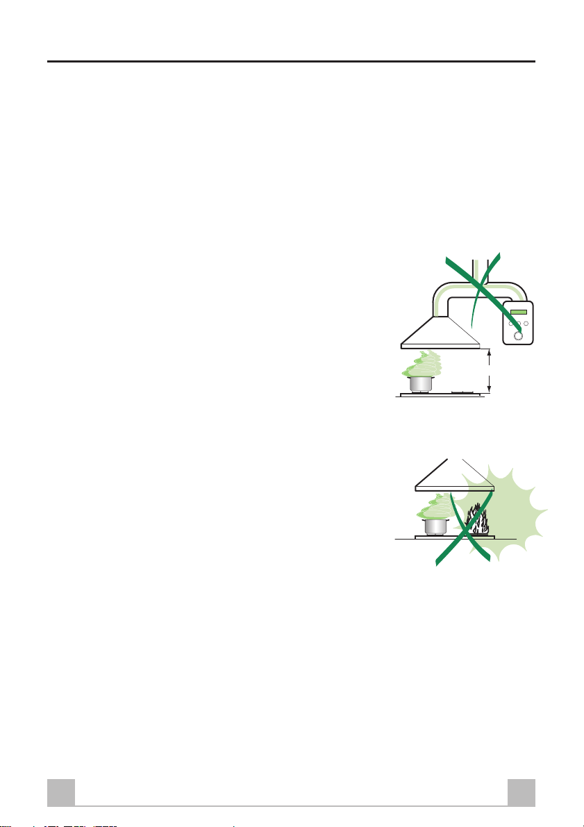
• The minimum safety distance between the cooker top and the
extractor hood is 650 mm.
• Check that the mains voltage corresponds to that indicated on the
rating plate fixed to the inside of the hood.
• For Class 1
guarantees adequate earthing.
• Connect the extractor to the exhaust flue through a pipe of
minimum diameter 120 mm. The route of the flue must be as short
as possible.
• Do not connect the extractor hood to exhaust ducts carrying
combustion fumes (boilers, fireplaces, etc.).
• If the extractor is used in conjunction with non-electrical appliances
(e.g. gas burning appliances), a sufficient degree of aeration must
be guaranteed in the room in order to prevent the backflow of
exhaust gas. The kitchen must have an opening communicating
directly with the open air in order to guarantee the entry of clean
air.
USE
• The extractor hood has been designed exclusively for domestic
use to eliminate kitchen smells.
• Never use the hood for purposes other than for which it has ben
designed.
• Never leave high naked flames under the hood when it is in
operation.
• Adjust the flame intensity to direct it onto the bottom of the pan
only, making sure that it does not engulf the sides.
• Deep fat fryers must be continuously monitored during use:
overheated oil can burst into flames.
• The hood should not be used by children or persons not instructed
in its correct use.
• The appliance is not intended for use by young children or infirm
persons without supervision.
• Young children should be supervised to ensure that they do not
play with the appliance.
a
appliances, check that the domestic power supply
650 mm min.
MAINTENANCE
• Switch off or unplug the appliance from the mains supply before
carrying out any maintenance work.
• Clean and/or replace the Filters after the specified time period.
• Clean the hood using a damp cloth and a neutral liquid detergent.
3GB
Page 4
CHARACTERISTICS
Dimensions
740
100
507
108 244
898
300
150
360
max. 1145
min. 850
260
360
60
132
90
433
63
650 min.
4GB
Page 5

Components
15
14.1
12a
7.2.1 11
14
9
2.1
12c
Ref. Q.ty Product Components
1 1 Hood Body, complete with: Controls, Light,
Blower, Filters
2 1 Telescopic Chimney comprising:
2.1 1 Upper Section
2.2 1 Lower Section
8a 1 Right Air Outlet Grill
8b 1 Left Air Outlet Grill
9 1 Reducer Flange ø 150-120 mm
14 1 Hood Body Air Outlet Extension Piece consisting
of two Half Shells
14.1 2 Air Outlet Connection Extension
15 1 Air Outlet Connection
2
2.2
8b
8a
Ref. Q.ty Installation Components
7.2.1 2 Upper Chimney Section Fixing Brackets
11 6 Wall Plugs
12a 6 Screws 4,2 x 44,4
12c 4 Screws 2,9 x 9,5
11
12a
Q.ty Documentation
1 Instruction Manual
1
5GB
Page 6

INSTALLATION
Wall drilling and bracket fixing
1÷2
7.2.1
11
12a
650 min.
Wall marking:
• Draw a vertical line on the supporting wall up to the ceiling, or as high as practical, at the centre
of the area in which the hood will be installed.
• Draw a horizontal line at 650 mm above the hob.
• Place bracket 7.2.1 on the wall as shown about 1-2 mm from the ceiling or upper limit aligning
the centre (notch) with the vertical reference line.
• Mark the wall at the centres of the holes in the bracket.
• Place bracket 7.2.1 on the wall as shown at X mm below the first bracket (X = height of the upper
chimney section supplied), aligning the centre (notch) with the vertical line.
• Mark the wall at the centres of the holes in the bracket.
• Mark a reference point as indicated at 116 mm from the vertical reference line and 323 mm above
the horizontal reference line.
• Repeat this operation on the other side.
• Drill ø 8 mm holes at all the centre points marked.
• Insert the wall plugs 11 in the holes.
• Fix the brackets using the 12a (4,2 x 44,4) screws supplied.
• Insert the two screws 12a (4,2 x 44,4) supplied in the hood body fixing holes, leaving a gap of 56 mm between the wall and the head of the screw.
116
116
X
323
6GB
Page 7

12a
Vr
9
ø 120ø 150
Mounting the hood body
• Before attaching the hood body, tighten the two
screws Vr located on the hood body mounting
points.
• Hook the hood body onto the screws 12a
• Fully tighten support screws 12a
• Adjust screws Vr to level the hood body
Connections
DUCTED VERSION AIR EXHAUST SYSTEM
When installing the ducted version, connect the hood to the chimney using either a flexible or rigid
pipe ø 150 or 120 mm, the choice of which is left to the installer.
• To install a ø 120 mm air exhaust connection,
insert the reducer flange 9 on the hood body
outlet.
• Fix the pipe in position using sufficient pipe
clamps (not supplied).
• Remove any activated charcoal filters.
7GB
Page 8

14
14.115
8a
8b
RECIRCULATION VERSION AIR OUTLET
12c
8a
2.1
2.2
2
8b
7.2.1
12c
• Assemble the two halves of the hood body
extension piece 14.
• Push fit the assembled hood body extension
piece 14 onto the air outlet.
• Push fit connection 15 onto the hood body
extension piece 14.
• Insert the connection extension pieces laterally
14.1 in connection 15.
• Make sure that the outlet of the extension pieces
14.1 is horizontally and vertically aligned with
the chimney outlets. If this is not the case, adjust
the position by either reversing the connection
extension pieces 14.1 or by cutting the hood
body extension 14 along one of the thinner
section channels denoting the pre-fixed lengths,
then reassemble as described previously .
• The air outlet directional grills 8a - 8b must be
fitted after the lower outlet duct has been
installed.
• Ensure that the activated charcoal filters have
been inserted.
ELECTRICAL CONNECTION
• Connect the hood to the mains through a two-pole switch having a contact gap of at least 3 mm.
Flue assembly
Upper exhaust flue
• Slightly widen the two sides of the upper flue
and hook them behind the brackets 7.2.1,
making sure that they are well seated.
• Secure the sides to the brackets using the 4
screws 12c (2,9 x 9,5) supplied.
Lower exhaust flue
• Slightly widen the two sides of the flue and hook
them between the upper flue and the wall,
making sure that they are well seated.
• Fix the lower part laterally to the hood body
using the 2 screws 12c (2,9 x 9,5) supplied.
• On the recirculation version, fit the directional
grids 8a – 8b in their housings making sure that
the directional symbols are towards the top and
front of the hood. Also make sure that they are
correctly inserted in the connection extension
pieces 14.1.
8GB
Page 9

USE
Control panel
L
S
V1 V2 V3
L Light Switches the lighting system on and off.
S Led Motor running led.
V1 Motor Switches the extractor motor on and off at low speed. Used to provide a contin-
uos and silent air change in the presence of light cooking vapours.
V2 Speed Medium speed, suitable for most operating conditions given the optimum treated
air flox/noise level ratio.
V3 Intensive Maximum speed, used for eliminating the highest cooking vapour emission,
including long periods.
9GB
Page 10

MAINTENANCE
Grease filters
CLEANING METAL SELF- SUPPORTING GREASE FILTERS
• The filters must be cleaned every 2 months of
operation, or more frequently for particularly
heavy usage, and can be washed in a dishwasher.
• Remove the filters one at a time by pushing
them towards the back of the group and pulling
down at the same time.
• Wash the filters, taking care not to bend them.
Allow them to dry before refitting.
• When refitting the filters, make sure that the
handle is visible on the outside.
Activated charcoal filter (Recirculation version)
REPLACING THE ACTIVATED CHARCOAL FILTER
• The filter is not washable and cannot be
regenerated, and must be replaced approximately
every 4 months of operation, or more frequently
for particularly heavy usage.
• Remove the metal grease filters
• Remove the saturated activated carbon filter by
releasing the fixing hooks
• Fit the new filter by hooking it into its seating
• Replace the metal grease filters.
Lighting
LIGHT REPLACEMENT
20 W halogen light.
• Remove the 2 Screws fixing the Lighting
support, and pull it out of from the Hood.
• Extract the Lamp from the Support.
• Replace with another of the same type, making
sure that the two pins are properly inserted in
the lamp holder socket holes.
• Replace the Support, fixing it in place with the
two Screws removed as above.
10GB
Page 11

Page 12

This appliance conforms to European Low Voltage Directive 73/23/CEE governing electrical safety, European Directive 89/
336/CEE on Electromagnetic Compatibility and Directive 93/68/CEE regarding CE Marking.
436001716 01 - 030311
 Loading...