

Page 1
Instructions Manual
Manuel d’Instructions
Bedienungsanleitung
Manual de instrucciones
Kullanim Kilavuku
EFC 6540
EFC 7540
EFC 9540
EFC 1540
Page 2

EN
Instructions Manual
INDEX
RECOMMENDATIONS AND SUGGESTIONS......................................................................................................................7
CHARACTERISTICS..............................................................................................................................................................8
INSTALLATION ......................................................................................................................................................................9
USE.......................................................................................................................................................................................12
MAINTENANCE....................................................................................................................................................................14
2
2
Page 3

DE
Bedienungsanleitung
INHALTSVERZEICHNIS
EMPFEHLUNGEN UND HINWEISE....................................................................................................................................16
CHARAKTERISTIKEN..........................................................................................................................................................17
MONTAGE............................................................................................................................................................................18
BEDIENUNG.........................................................................................................................................................................21
WARTUNG............................................................................................................................................................................23
3
3
Page 4

FR
Manuel d’Instructions
SOMMAIRE
CONSEILS ET SUGGESTIONS ..........................................................................................................................................25
CARACTERISTIQUES.........................................................................................................................................................26
INSTALLATION ....................................................................................................................................................................27
UTILISATION........................................................................................................................................................................30
ENTRETIEN..........................................................................................................................................................................32
4
4
Page 5

ES
Manual de instrucciones
ÍNDICE
CONSEJOS Y SUGERENCIAS ...........................................................................................................................................34
CARACTERÍSTICAS............................................................................................................................................................35
INSTALACIÓN......................................................................................................................................................................36
USO......................................................................................................................................................................................39
MANTENIMIENTO................................................................................................................................................................41
5
5
Page 6

TR
Kullanim Kilavuku
IÇERIKLER
TAVSIYELER VE ÖNERILER ..............................................................................................................................................43
ÖZELLIKLER........................................................................................................................................................................44
MONTAJ...............................................................................................................................................................................45
KULLANIM............................................................................................................................................................................48
BAKIM...................................................................................................................................................................................50
6
6
Page 7

EN
RECOMMENDATIONS AND SUGGESTIONS
INSTALLATION
• The manufacture r will not be held liable for any damages resulting
from incorrect or improper installation.
• The minimum safety distance between the cooker top and the extrac tor hood is 650 mm.
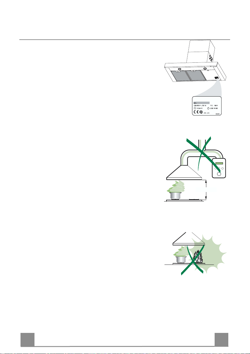
• Check that the mains voltage corresponds to that indicated on the
rating plate fixed to the inside of the hood.
• For Class I applianc es, c heck t hat th e domes tic po wer suppl y gua rantees adequate earthing.
Connect the extractor to the ex haust flue through a pi pe of minimum
diameter 120 mm. The route of the flue must be as short as possible.
• Do not connect the extractor hood to exhaust ducts carryi ng combustion fumes (boilers, fireplaces, etc.).
• If the extractor is used in conjuncti on with non-electrical appliances
(e.g. gas burning appliances), a suffici ent degree of aeration must be
guaranteed in the room in order to prevent the backflow of exhaust
gas. The kitchen must have an opening communicating directl y with
the open air in order to guarantee the entry of clean air.
USE
• The extractor hood has been designe d ex cl usi vely for domesti c us e to
eliminate kitchen smells.
• Neve r use the hood for pu rposes other than fo r which it has ben designed.
• Never leave high naked flames under the hood when it is in operation.
• Adjus t the flame intensity to direct it onto the bottom of the pan only,
making sure that it does not engulf the sides.
• Deep fat fryers must be continuously monitored during use: overheated oil can burst into flames.
• Do not flambè under the range hood; risk of fire
• The hood should not be used by chil dren or persons not inst ructed in
its correct use.
MAINTENANCE
• Switch off or unplug the appliance from the mains supply before carrying out any maintenance work.
• Clean and/or replace the Filters after the specified time period.
• Clean the hood using a damp cloth and a neutral liquid detergent.
650 mm min.
7
7
Page 8
EN
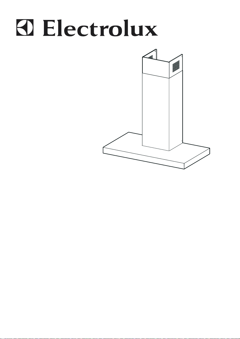
CHARACTERISTICS
740
598-698-898-1198
300
150
108
490 60
870
Dimensions
64
1200
260
42
650 min.
Components
Ref. Q.ty Product Components
1 1 Hood Body, complete with: Controls, Light, Blower,
Filters
2 1 Telescopic Chimney comprising:
2.1 1 Upper Section
2.2 1 Lower Section
9 1 Reducer Flange ø 150-12 0 mm
10 1 Damper ø 150
14.1 2 Air Outlet Co nnection Extension
15 1 Air Outlet Connection
Ref. Q.ty Installation Components
7.2.1 2 Upper Chimney Section Fixing Brackets
7.3 1 Air Outlet Connecti on Support
11 6 Wall Plugs
12a 6 Screws 4,2 x 44,4
12c 6 Screws 2,9 x 9,5
Q.ty Documentation
1 Instruction Manual
7.3
9
10
2.1
2
2.2
1
15
12a
14.1
7.2.1 11
12c
11
12a
8
8
Page 9
EN
INSTALLATION
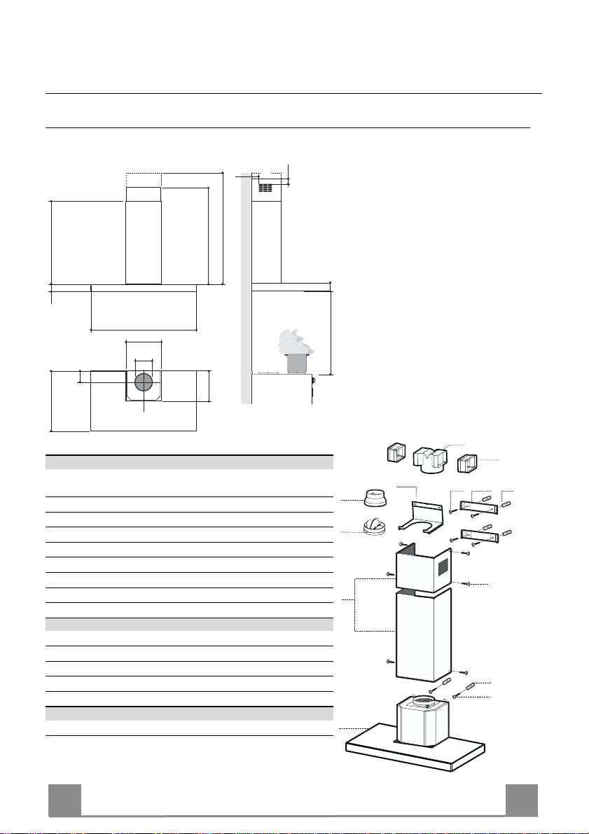
Wall drilling and bracket fixing
1÷2
7.2.1
11
12a
650 min.
116
116
X
320
Wall marking:
• Draw a vertical line on the supporting wall up to the ceiling, or as high as practical, at the
centre of the area in which the hood will be installed.
• Draw a horizontal line at 650 mm above the hob.
• P l ace bracket 7.2.1 on the wall as shown about 1-2 mm from the ceiling or upper limit aligning the centre (notch) with the vertical reference line.
• Mark the wall at the centres of the holes in th e br acket.
• P l ace br acket 7.2.1 on the wall as shown at X mm below the first bracket (X = height of the
upper chimney section supplied), aligning the centre (notch) with the vertical line.
• Mark the wall at the centres of the holes in th e br acket.
• Mark a reference point as in dicated at 116 mm from the vertical reference li ne and 320 mm
above the horizontal reference l ine.
• Repeat this operation on the other side.
• Drill ø 8 mm holes at all the centre points marked.
• Insert the wall plugs 11 in the holes.
• Fix the lower bracket 7.2.1 using the 12a screws (4,2 x 44,4) supplied.
• Fix the upper bracket 7.2.1 and the air outlet connection supp ort 7.3 to gether using the 2
screws 12a (4,2 x 44,4) supplied.
• Insert the two screws 12a (4,2 x 44,4) supplied in the hood body fixing holes, leaving a gap
of 5-6 mm between the wall and the head of the screw.
9
9
Page 10
EN 110
9
ø 120ø 150
10
10
ø 150
14.1
15
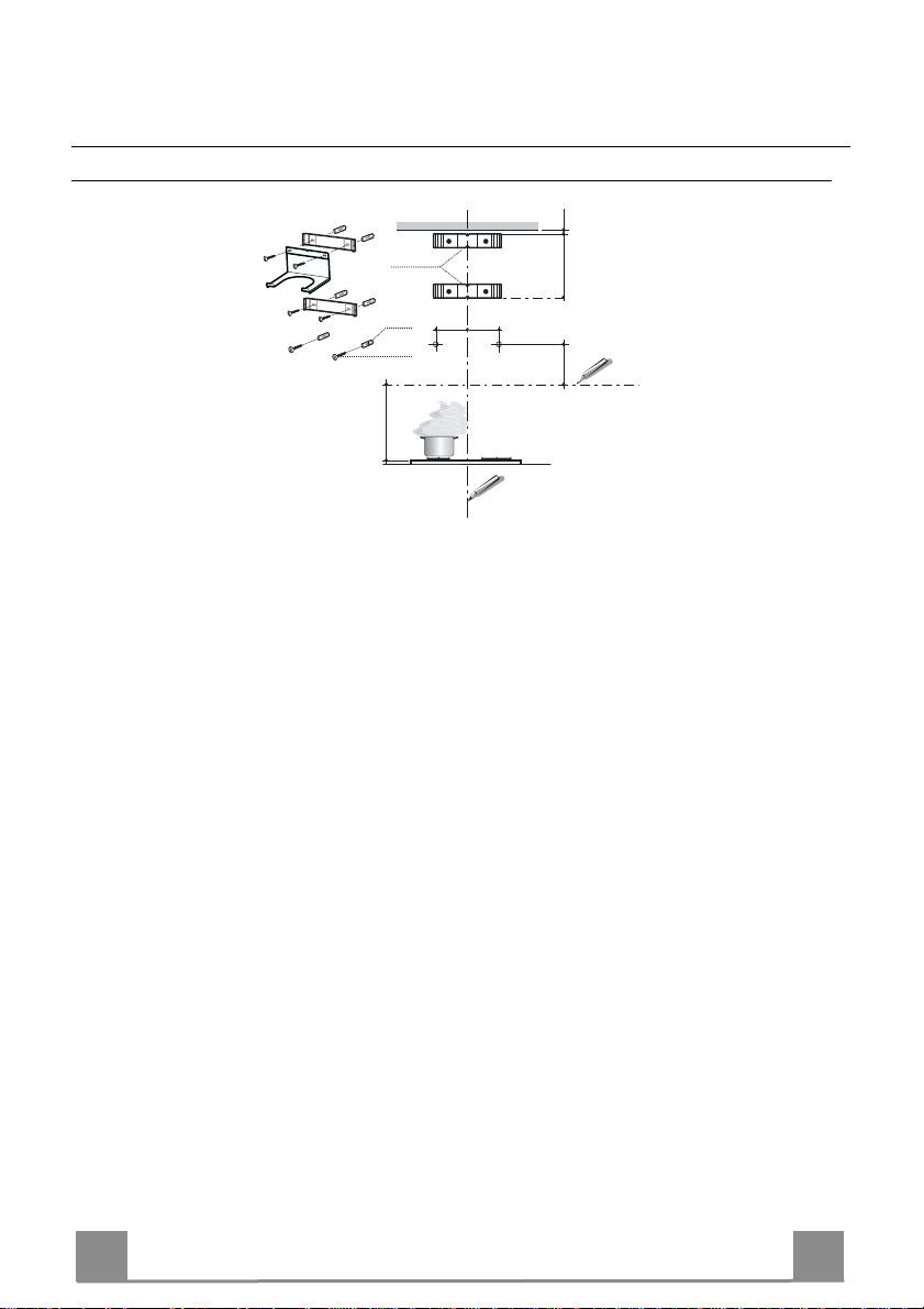
Mounting the hood body
• Before attaching the hood body, tighten the two screws Vr located on the hood body mounting points.
• Hook the hood body onto the screws 12a.
• Fully tighten support screws 12a.
• Adjust screws Vr to level the hood body.
Connections
DUCTED VERSION AIR EXHAUST SYSTEM
When installing the ducted version, connect the hood to the
chimney using either a flexible or rigid pipe ø 150 or 120mm, the
choice of which is left to the installer.
To install a ø 150
• To install the dumper 10
• Fix the pipe in position using sufficient pipe clamps (not supplied).
To install a ø 120
• To install a ø 120 mm air exhaust connection, insert the reducer flange 9 on the dumper 10.
• Fix the pipe in position using sufficient pipe clamps (not supplied).
• Remove an y activated charcoal filters.
Vr
12a
RECIRCULATION VERSION AIR OUTLET
• Put connection 15 into the connection support 7.3.
• Insert the conn ection exten sion pieces lat erally 14.1 in co nnection 15.
• Make sure that t he outlet of the extension pieces 14.1 is horizontally and vertically aligned with the chimney outlets.
• Connect the air outlet co nnection 15 to the hood body outlet
using either a flexible or rigid pipe ø 150 mm, the choice of
which is left to the installer.
• Ensure that the activated charcoal filters have been inserted.
Page 11
EN 111
12c
2.1
2.2
2
7.2.1
12c
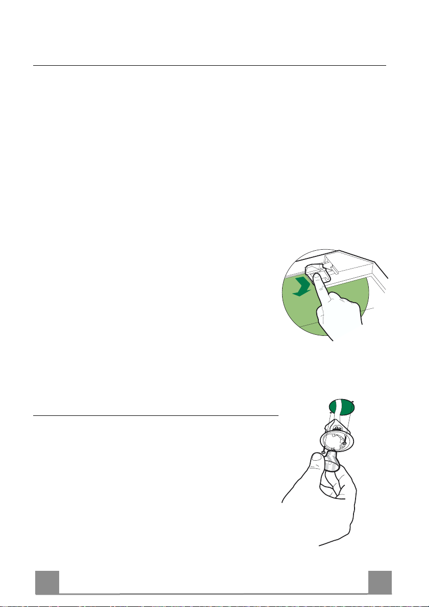
ELECTRICAL CONNECTION
• Connect the hood to the mains through a two-pole switch having a contact gap of at least 3 mm.
• Re move the grease filters (see paragraph Maintenance) being
sure that the conn ector of the feeding cable is correctly inserted
in the socket placed on th e side of the fan.
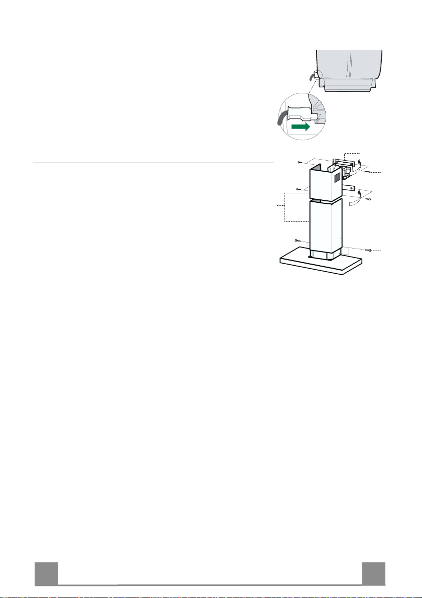
Flue assembly
Upper exhaust flue
• Slightly widen the two sides of the upper flue and hook them
behind the brackets 7.2.1, making sure that they are well
seated.
• Secure the sides to the brackets using the 4 screws 12c (2,9 x
9,5) supplied.
• Make sure that the outlet of the extension s pieces is aligned
with the chimney outlets.
Lower ex haust flue
• Slightly widen the two sides of the flue and hook them between the upper flue and t he wall, making sure that they are
well seated.
• Fix the lower part laterally to the hood body using the 2 screws
12c (2,9 x 9,5) supplied.
Page 12
EN 112
Dual Function
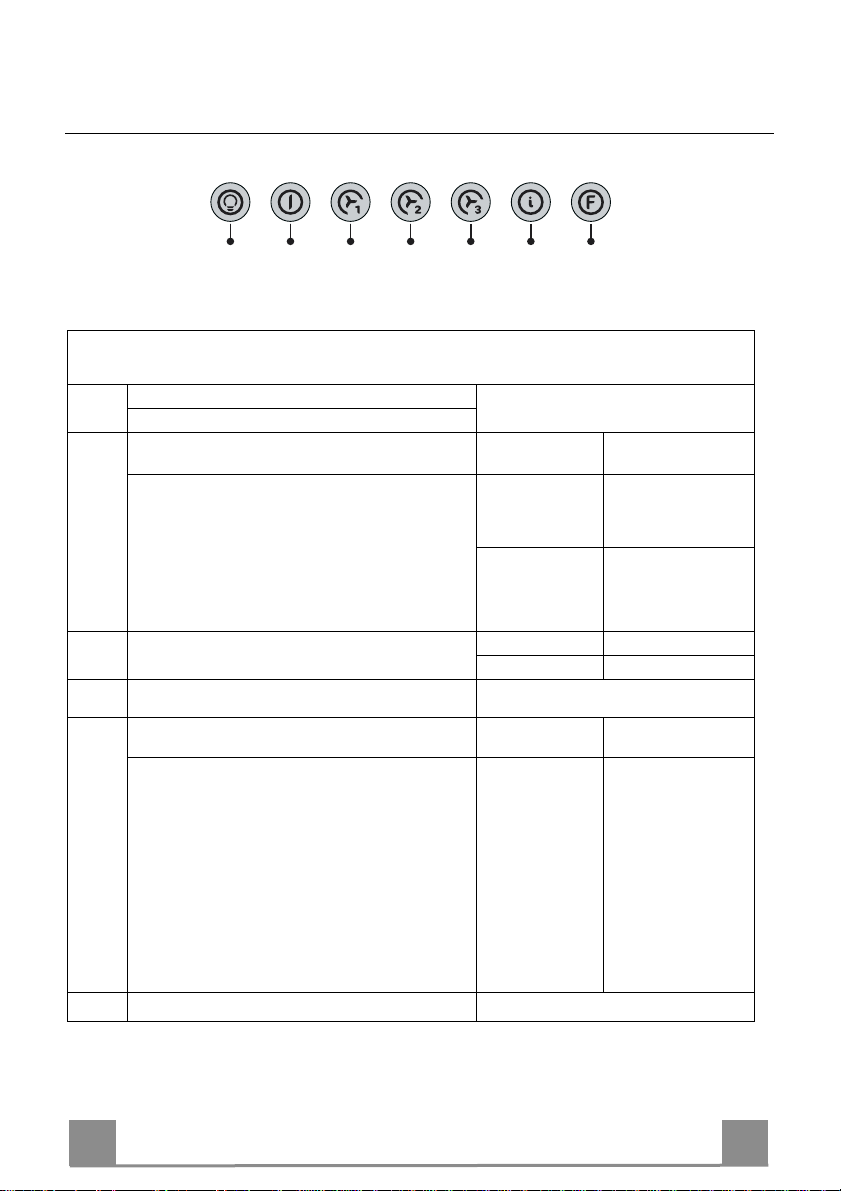
USE
L T1 T2 T3 T4 T5 F
The hood can be switched on pushing directly onto the requested speed without firstly having to select 0/1 button .
Touch
Basic functions
control
When briefly pressed it switches the lighting system
L
on and off.
When pressed for 2 seconds it starts the lighting
system in “courtesy light” mode. The lamps are
fed at a reduced power of approximately 5W.
Such function can be stopped by pressing the
touch control for 2 seconds or just by pressing it
shortly in order to return to the normal lighting
mode. In courtesy light mode the touch control is
not lit.
When pressed the motor is stopped, regardless of the
T1
speed it is set to.
When pressed the motor is set to the first speed
T2
By a brief pressing the motor is set to the second
T3
speed.
By pressing the touch control for approximately 2
seconds the Delay function is enabled, i.e delayed shutdown of the appliance ensuring a complete elimination of the residual odours. This function can be activated at OFF-position and at 1°,
2° and 3°speeds. It can be stopped in advance
by pressing any of the touch controls (T) with the
exception of T3. The Delay function works according to the following scheme:
When pressed the motor is set to the third speed
T4
1°speed / OFF = 20 minuets
2°speed = 15 minutes
3°speed = 5 minutes
Indicator lights
Touch control unlit Lights off
Touch control lit Lights on
Touch control unlit Courtesy light on
Touch control lit Motor on
Touch control unlit Motor off
Touch control lit
Touch control lit Second speed on
Flashing touch
control
Touch control lit
Delay function on
Page 13
EN 113
Touch control lit
Touch
control
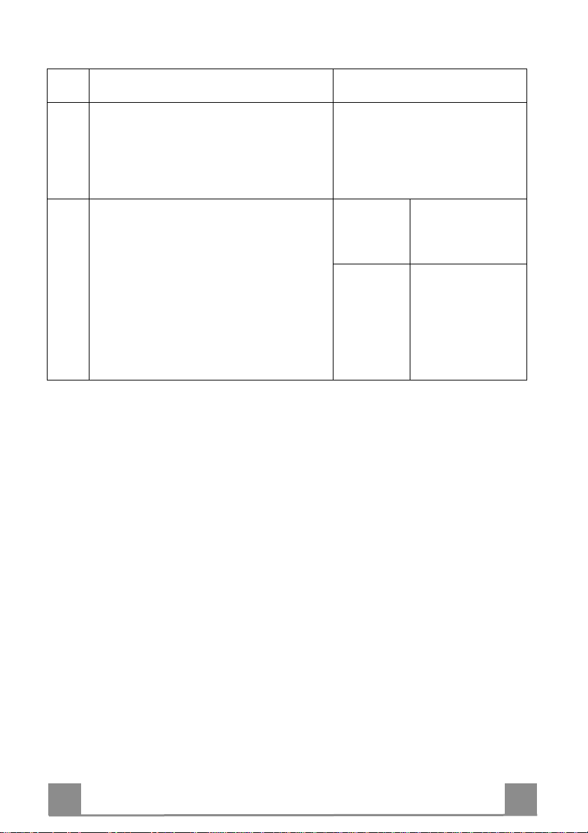
T5
Basic functions Indicator lights
When pressed the motor is set to the intensive speed
timed to 5 minutes. At the end of 5 minutes of intensive speed the hood starts again at the speed it was
set to previously. In case the hood is set to the intensive speed directly from OFF-state it will then start
from the first speed after 5 minutes of intensive
speed.
When pressed for 4 seconds it resets the filter alarm
F
signal indicated by flashing of the touch control T1.
This procedure can be carried out only when the motor is stopped.
Flashing touch
control
Touch control lit
Metal grease filters saturation alarm. Metal gr e ase
filters need to be washed.
The alarm star ts up after
100 working hours.
Charcoal odour filter saturation alarm. Char coal
filter has to be replaced
and metal grease filters
washed. The alarm starts
up after 200 working
hours. (Activation; chec k
the paragraph “Odour
filter”)
Page 14
EN 114
MAINTENANCE
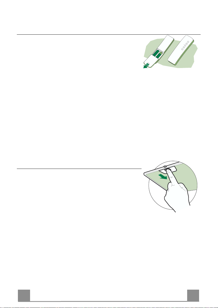
REMOTE CONTROL (OPTIONAL)
The appliance can be controlled using a remote control powered
by a 1.5 V carbon-zinc alkaline batteries of the standard LR03AAA type.
• Do not pl ace the remote control near to heat sources.
• Used batteries must be disposed of in the proper manner.
Grease filters
CLEANING OF THE METAL CASSETTE FILTERS
Alarm reset
• Stop the motor.
• Press the F -touch control for at least 4 seconds until the T1 -
touch control flashes.
Cleaning the filters
• Filters can be washed in the dish machine. They need to be
washed every 2 mont hs o r even more fr equ en tly in case of particularly intensive use of the hood.
• Remove the filters one by one pushing them towards the back
side of the unit and simultaneously pulling downwards.
• Any kind of bending of the filters has to be avoided when
washing them. Before fitting them again into the hood make
sure that they are completely dry.
• When fitting the filters into the hood pay attention that they are
mounted in correct position and that the handle faces outwards.
Page 15
EN 115
Odour filter (Recirculation Version)
This filter cannot be washed or regenerated, and must be replaced when the F touch control starts
to flash, or at least once ev e ry 4 months. The alarm is only trigge re d w he n the m otor is on.
Enabling/Disabling the alarm signal
• In Recirculation Version Hoods, the Filter saturation Alarm must be enabled at the time of
installation or later.
• Switch off the lights and the motor.
• Disconnect the mains power supply to the hood by removing the motor unit power supply
cable connector, switching off the power supply at the Mains or turning the Main switch off.
• Restore the connection, pressing and holding T2.
• Release the touch control, touch controls L, T2 and F will light up normally.
• Within 3 seconds press the touch control F until the key itself flashes to confirm as follows:
• 2 flashes – Charcoal odour Filter saturation Alarm ENABLED
• 1 flash - Charcoal odour Filter saturation Alarm DISABLED
REPLACING THE CHARCOAL ODOUR FILTER
Reset the alarm signal
• Stop the motor.
• P ress the touch control F for at least 4 seconds, until the touch
control T1 flashes.
Replace the Filter
• Remove the metal grease filters.
• Remove the saturated ch arcoal filter, t urning the fast eners provided.
• Fit the new filter and fasten it its correct position.
• Put the metal grease filters in their seats.
Lighting
LIGHT REPLACEMENT
20 W halogen light.
• Remove the 2 screws fixing the Lighting support, and pull it
out of from the Hood.
• Extract the lamp from the Support.
• Replace with another of the same type, making sure that the
two pins are properly inserted in the lamp holder socket holes.
• Rep lace the Support, fixing it in place with the two screws removed as above.
Page 16
DE 116
EMPFEHLUNGEN UND HINWEISE
MONTAGE
• Der Herstell er haftet nicht für Schäden, die auf ein e fehlerhafte und
unsachgemäße Montage zurückzuführen sind.
• Der minimale Sicherheitsabstand zwischen Kochmulde und Haube
muss 650 mm betragen.
• Prüfen, ob die Netzspannung mit dem Wert au f dem im Haubeninneren angebrachten Schild übereinstimmt.
• Bei Geräten d er Klasse I ist sicherz ustellen, dass die elektri sche Anlage des Wohnhauses über eine vorschriftsmäßige Erdung verfügt.
• Das Anschlussrohr der Haube zur Luftaustrittsöffnung muss einen
Durchmesser von 120 mm oder darüber aufweisen. Der Rohrverl auf
muss so kurz wie möglich sein.
• Die Haube darf an keine Entlüftungs schächte anges chloss en werden,
in die Verbrennungsgase (Heizkessel, Kamine usw.) geleitet werden.
• Werden im Raum außer der Dunsta bzugshaube andere, nicht elektrisch betriebene (z.B. gasbetri ebene) Geräte verwendet, muss für eine ausreichende Belüftung gesorgt werden. Sollte die Küche diesbezüglich nicht entsprechen, ist an ein er Aussenwand eine Öffn ung anzubringen, die Frischluftzufuhr gewährleistet.
BEDIENUNG
• Die Dunstabzugshaube ist ausschließlich zum Einsatz im privaten
Haushalt und zur Beseitigung von Küchengerüchen vorgesehen.
• Unsachgemäßer Einsatz der Haube ist zu unterlassen.
• Große Flammen bei eingeschalteter Haube niemals unbedeckt lassen.
• Die Intensivität der Flamme i st so zu reguliere n, dass s ie den Topfboden nicht überragt.
• Frittiergeräte müssen während des Gebrauchs stets beaufsichtigt
werden: überhitztes Öl kann sich entzünden.
• Keine flambierten Speisen unter der Abzugshaube zubereiten:
Brandgefahr.
• Die Dunstabzugshaube da rf vo n Kindern oder Pe rsonen, die hins ichtlich der Bedienung nicht unterwi esen wurden, keinesfalls verwendet
werden.
WARTUNG
• Bevor Wa rtungsarbeiten du rchgeführt werden, mus s die Stromzufuh r
zur Haube unterbrochen werden, indem der Stecker gezogen oder
der Hauptschalter abgeschaltet wird.
• Bei der F ilterwartung müssen die vom Hersteller empfohlenen Zeiträume zum Austauschen der Filter genauestens eingehalten werden.
• Zur Reinigung der Haubenfl ächen Wir empfehlen ein feuchtes Tuch
und ein mildes Flüssigreinigungsmittel.
650 mm min.
Page 17

DE 117
CHARAKTERISTIKEN
740
598-698-898-1198
300
150
108
490 60
870
260
64
1200
Platzbedarf
42
650 min.
Komponenten
Pos. St. Produktkomponenten
1 1 Haubenkörper mit Schaltern,Beleuchtung, Gebläse-
gruppe,Filter
2 1 Teleskopkamin bestehend aus:
2.1 1 oberer Kaminteil
2.2 1 unterer Kaminteil
7.3
9
10
15
12a
14.1
7.2.1 11
9 1 Reduzier flansch ø 150-120 mm
10 1 Flansch mit Ruckstauklappe
14.1 2 Verlängerung Luftaustritt-Anschlussstück
15 1 Luftaustritt-Anschlussstück
2.1
2
12c
Pos. St. Montagekomponenten
2.2
7.2.1 2 Befestigungsbügel o berer Kaminteil
7.3 1 Bügel für Anschlusshalter
11 6 Bügel
12a 6 Schrauben 4,2 x 44,4
12c 6 Schrauben 2,9 x 9,5
St. Dokumentation
1
11
12a
1 Bedienungsanleitung
Page 18

DE 118
MONTAGE
Bohren der Befestigungslöcher und Fixieren der Befestigungsbügel
1÷2
7.2.1
11
12a
650 min.
116
116
X
320
Nachstehende Linien an die Wand zeichnen:
• Eine vertikale Linie bis zur Decke oder oberen Begrenzung, und zwar in der Mitte des Bereiches,in dem die Haube montiert werden soll;
• Eine horizonta le Linie: mit einem minimalen Abstand von 650 mm zur Kochfläche.
• Einen Bügel 7.2.1 zirka 1-2 mm unter der Decke oder oberen Begrenzung an die Wand legen und
seinen Mittelpunkt (Einschnitte) auf die vertikale Bezugslinie ausrichten.
• Die Mitte der beiden Bügellöcher an der Wand markieren.
• Den zweiten Bügel 7.2.1 an die Wand legen, wobei ei n Abstand X mm vom oberen Bügel einzu-
halten ist (X = Höhe des jeweiligen oberen Kaminteils); den Mittelpunkt (Einschnitte) auf die vertikale Bezugslinie aus richten.
• Die Mitte der Bügellöcher an der Wand markieren.
• Wie beschri eben einen Bezugspunkt 116 mm von der vertikalen Bezugslinie und 320 mm oberhalb der horiz ontalen Bezugslinie kennzeichnen.
• Gleichermaßen an der gegenüberliegenden Seite vorgehen.
• Mit einem Bohrer ø 8 mm die markierten Punkte bohren.
• Die Dübel 11 in die Bohrungen einfügen.
• Den unteren Bü gel mit den mitgelieferten Schrauben 12a (4,2 x 44,4) fixieren.
• Den Bügel für Anschlusshalter mit den 2 mitgelieferten Schrauben 12a (4,2 x 44,4) auf den obe-
ren Bügel 7.2.1 befestigen.
• 2 der mitgelieferten Schrauben 12a(4,2 x 44,4)bei den Befestigungslöchern des Haubenkörpers
einschrauben, wobei zwischen Wand und Schraubenk opf ein Freiraum von 5-6 mm zu bela ssen
ist.
Page 19

DE 119
9
ø 120ø 150
10
10
ø 150
14.1
15
Montage des Haubenkörpers
• Bevor der Haubenkörper eingehakt wird, die 2 Schrauben Vr
bei den Haubenkörper-Anhakpunkten festziehen.
• Den Haubenkörper bei den Schrauben 12a e inhä ng e n.
• Die Halteschrauben 12a definitiv festziehen.
• Den Haubenkörper mit Hilfe der Schrauben Vr ausrichten.
Anschlüsse
ANSCHLUSS IN ABLUFTVERSION
Bei Abluftbetrieb kann die Haube vom Installateur wahlweise
mittels Rohr oder Schlauch (ø150 oder 120mm) an die Außenrohrleitung angeschlossen werden.
Anschlussrohres ø 150
• Den Flansch mit Ruckstauklappe 10 anbringen.
• Das Rohr mit geeignet en Rohrschellen fixieren.Das hi erzu erforderliche Material wird nicht mitgeliefert.
Anschlussrohres ø 120
• Bei Verwendung eines Anschlussrohres ø 120 den Reduzierflansch 9 am Flansch mit Ruckstauklappe 10 anbringen.
• Das Rohr mit geeignet en Rohrschellen fixieren.Das hi erzu erforderliche Material wird nicht mitgeliefert.
• Eventuell vorhandene Aktivkohlefilter entnehmen.
Vr
12a
Anschluss der Umluftversion
• Den Anschluss 15 am Anschlusshalter 7.3 anbringen.
• Die Verl ängeru ngen 14.1 beim Anschluss 15 seitlich einfügen.
• Überpr üfen, ob die V erlängerungen 14.1 mit den entsprechenden Kaminstutzen sowohl horizontal wie auch vertikal übereinstimmen.
• Vom Installateur wahlweise mittels Rohr oder Schlauch (ø 150
mm), den Anschluss 15 am Haubenaustritt anbringen.
• Kontrollieren, ob der Aktivkohle-Geruchsfilter montiert ist.
Page 20

DE 220
12c
2.1
2.2
2
7.2.1
12c
ELEKTROANSCHLUSS
• Bei Anschluss der Haube an das Stromnetz muss ein zweipoliger Schalter mit einem Öffnungsweg von mindestens 3 mm
zwischengeschaltet werden.
• Entfernen Sie die Fettfilter (s. Abschnitt „Wartung“) und versichern Sie sich, daß di e Kabelverbindung in die Steckd ose des
Gebläses einwandfrei eingesteckt wird.
Kaminmontage
Oberer Kaminteil
• Die beiden seitlichen Schenkel leicht auseinanderbiegen, hinter
den Bügeln 7.2.1 einhängen und bis zum Anschlag wieder
schließen.
• Bei den Bügeln 7.2.1 mit Hilfe der 4 mitgelieferten Schrauben
12c fixieren.
• Überprüfen, ob die Verlängerungen mit den entsprechenden
Kaminstutzen überein stimmen.
Unterer Kaminteil
• Die beiden seitlichen Schenkel des Kaminteils leicht auseinander biegen, zwischen dem oberen Kaminteil und der Wand
einhängen und bis zum Anschlag wieder schließen.
• Den unteren Teil seitlich am Haubenkörper mit 2 der mitgelieferten Schrauben 12c fixieren.
Page 21

DE 221
BEDIENUNG
L T1 T2 T3 T4 T5 F
Die Haube kann direkt auf die gewünschte Stufe eingeschaltet werden ohne daß man vorher
auf die Gebläsetaste 0/1 drückt.
Grundfunktion
Taste
Doppelfunktion
Ein kurzer Tas tendruck schaltet die Bel euchtungsanlage
L
ein und aus.
Wird die Taste 2 Sekunden lang gedrückt, schaltet sich
die “Nachtbeleuchtung” ein. Die Lampen werde n mit
einer verringerten Leistung von cirka 5W gespeist. Diese Funktion kann deakti viert werden , indem die Taste 2
Sekunden lang gedrückt wird bzw. kurz gedrückt wird,
um auf den normalen Beleuchtungsmodus überzugehen. Im Modus „Nachtbeleuchtung“ leuchtet die Taste
nicht auf.
Schaltet den Motor unabhängig von der Gebläsestufe ab
T1
Aktiviert den Motor mit der ersten Gebläsestufe
T2
Bei kurzem Drüc ken dieser T aste wird der Mot or mit der
T3
zweiten Gebläsestufe aktiviert
Wird die Tast e cirka 2 Sekun den lang gedrückt, akti viert
sich die Funkt ion Delay, d.h. die verzögerte Abschaltung des Gerätes. Eignet sich zur kompletten Beseitigung von Rest gerüchen. Kann in der Position OFF und
den Gebläses tufen 1, 2, 3 aktiviert werd en; kann vorzeitig durch Drüc ken jeder beliebigen Taste (T) (mit Aus-
nahme der Tas te T3) deaktiviert werden. Die DelayFunktion erfolgt nach nachstehendem Zeitplan:
1. Stufe / OFF = 20 Minuten
2. Stufe = 15 Minuten
3. Stufe = 5 Minuten
Aktiviert den Motor mit der dr itten Gebläsestufe
T4
Taste erloschen
Taste leuchtet auf
Taste erloschen
Taste leuchtet auf
Taste erloschen
Taste leuchtet auf
Taste blinkt Delay-Funktion akt i vi ert
Leuchtsignale
Beleuchtung abgeschalt et
Beleuchtung eingeschaltet
Nachtbeleuc ht ung ei n geschaltet
Motor aktiviert
Motor deaktivi ert
Taste leuchtet auf
Zweite Gebläsestufe aktiviert
Taste leuchtet auf
Page 22

DE 222
Taste
T5
Grundfunktion
Aktiviert den Motor mit der 5 Minuten dauernden Intensivstufe. Nach Ablauf der 5 Min uten läuft das Gerät wieder
mit der zuvor eingestellten Sauggeschwindigkeit. Wird
diese Funktion bei ab ges c hal tetem Ger ät ak t iv ier t , wird
nach Ablauf der 5 Minute n auf die ers te Gebläsestufe
übergegangen.
Wird die Taste 4 Sekunden lang gedrückt, erfolgt die
F
Rückstellung des Filteralarms, der durch Blinken der Taste T1 angezeigt wird. Dieses Verfahren kann nur bei abgeschaltete m Motor durchgeführt werden.
Leuchtsignale
Taste leuchtet auf
Taste leuchtet auf
Taste blinkt Sättigungsanzeige der Ak-
Sättigungsanzeige der M etallfettfilter, die gewaschen
werden müssen. Der Alarm
erfolgt nach 100 effektiven
Arbeitsstund en der Ha ube.
tivkohle-Geruchsfilter , falls
diese aktiv iert wurde; die
Filter sind auszutauschen;
die Metallfettfilter müssen
ebenfalls gewaschen werden. Die Sättigungsanzeige
des AktivkohleGeruchsfilters erfolgt nach
200 effektiven Arbeitsstunden der Haube. (Aktivierung
siehe Abschn.
Geruchsfilter)
Page 23

DE 223
WARTUNG
FERNBEDIENUNG (OPTION)
Dieses Gerät kann mit einer Fernbedienung gesteuert werden,
welche mit alkalischen Zink-Kohle-Batterien 1,5 V des Standardtyps LR03-AAA versorgt wird.
• Die Fernbedienung nicht in die Nähe von Hitzequellen legen.
• Batterien müssen vorschriftsmäßig entsorgt werden.
Fettfilter
REINIGUNG DER SELBSTTRAGENDEN METALLFETTFILTER
Rückstellen der Sättigungs anzeige
• Den Gebläsemotor abschalten.
• Die Taste F mindestens 4 Sekunden lang drücken, bis die Taste
T1 als Bestätigung zu blinken beginnt.
Filterreinigung
• Die Filter können auch im Geschirrspüler gereinigt werden und
sollten cirka alle 2 Monate - bzw. bei sehr intensivem Einsatz
auch häufiger - gereinigt werden.
• Die Filter einzeln entnehmen, indem sie zur Rückseite der
Gruppe geschoben und gleichzeitig nach unten gezogen werden.
• Die Filter waschen, darauf achten, sie nicht zu verbiegen und
vor der Remontage trocknen lassen.
• Bei der Remontage darauf achten, dass sich der Griff an der
sichtbaren Außenseite befindet.
Page 24

DE 224
Geruchsfilter (Umluftbetrieb)
Dieser Filter ist weder wasch- noch wiederverwendbar und ist auszutauschen, wenn die Taste
F blinkt oder zumindest alle 4 Monate. Die Sättigungsanzeige erfolgt nur, wenn der Gebläsemotor eingeschaltet ist.
Aktivierung/Deaktivierungder S ättigungsa nzeige
• Bei Hauben mit Umluftbetrieb erfolgt die Aktivierung der Sättigungsanzeige bei der Installation oder später.
• Die Beleuchtung und den Gebläsemotor abschalten.
• Die Haube vom Stromnetz trennen, indem der Verbinder des Speisekabels der Motorgruppe
gezogen oder der zwischengeschaltete zweipolige Schalter oder der Hauptschalter betätigt
wird.
• Den Anschluss wieder herstellen, während die Taste T2 gedrückt gehalten wird.
• Die Taste loslassen; die Tasten L, T2 und F leuchten pausenlos auf.
• Inne rhalb von 3 Sekunden die Taste F solange drücken, bis sie als Bestätigung zu blin ken
beginnen:
• 2-maliges Blinken – Sättigungsanzeige Aktivkohle-Geruchsfilter AKTIVIERT
• 1-maliges Blinken – Sättigungsanzeige Aktivkohle-Geruchsfilter DEAKTIVIERT
AUSTAUSCHEN DES AKTIVKOHLE-GERU CHSF IL T ER
Rückstellen der Sättigungs anzeige
• Den Gebläsemotor abschalten.
• Die Taste F mindestens 4 Sekunden lang drücken, bis die Taste
T1 als Bestätigung zu blinken beginnt
Filterwechsel
• Die Metallfettfilter entfernen.
• Den gesättigten Aktivkohle-Geruchsfilter anhand der entsprechenden Anhakvorrichtungen demontieren.
• Den neuen Filter montieren, indem er in seinem Sitz eingehakt
wird.
• Die Metallfettfilter wieder montieren.
Beleuchtung
AUSWECHSELN DER LAMPEN
Halogenlampe 20 W
• Vor dem Auswechseln der Lampen, die beiden Schrauben der
Lampenhalterung loesen und die Lampenhalterung aus der
Dunstabzugshaube ziehen.
• Die Lampe aus der Halt erung nehmen.
• Die Lampe durch eine gleichwertige ersetzen und bei der Remontage darauf achten, daß die beiden Steckerstifte vorschriftsmäßig in die Lampenfassung eingeführt werden.
• Die Lampenhalterung wieder montieren, indem die beiden zuvor entfernten Schraub en wieder angezogen werden.
Page 25

FR 225
CONSEILS ET SUGGESTIONS
INSTALLATION
• Le fabricant d écline toute responsabilité en cas de dommage dû à
une installation non correcte ou non conforme aux règles de l’art.
• La di stance minimale de sécurité entre le plan de cuisson et l a hotte
doit être de 650 mm au moins.
• Vérifier que la tensi on du sec teu r c or respond à l a val eur qui fi gu re s ur
la plaquette apposée à l’intérieur de la hotte.
• Pour les Appareils appartenant à la I
mise à la terre de l’installation électrique domestique ait été effectuée
conformément aux normes en vigueur.
• Connecter la hotte à la sortie d’air aspiré à l’aide d’une tuyauterie
d’un diamètre égal ou supérieur à 120 mm. Le parcours de la
tuyauterie doit être le plus court possible.
• Eviter de connecter la hotte à des conduites d’évacuation de fumées
issues d’une combustion tel que (Chaudière, cheminée, etc…).
• Si vous utilisez des appareils qui ne fonctionnent pas à l’électricité
dans la pièce ou est installée la hotte (par exemple: des appareils
fonctionnant au gaz), vous devez prévoir une aération suffisante du
milieu. Si la cuisine en est dépou rvue, pratiquez une ouverture qui
communique avec l’extérieur pour garantir l’infiltration de l’air pur.
UTILISATION
• La hotte a é té conçue exclusivement pour l’usage domestique, dans
le but d’éliminer les odeurs de la cuisine.
• Ne jamais utiliser abusivement la hotte.
• Ne pas lai sser les flammes libres à forte intensité quand la hotte es t
en service.
• Toujours régler les flammes de manière à éviter toute sortie latérale
de ces dernières par rapport au fond des marmites.
• Contrôler les friteuses lors de l’utilisation car l’huile surchauffée
pourrait s’enflammer.
• Ne pas prépa rer d’aliments flambés s ous la hotte de cuisine : risque
d’incendie
• La hotte ne doit pas être utilisée par des enfants ou des per sonnes ne
pouvant pas assurer une utilisation correcte.
ENTRETIEN
• Avant de procéder à toute opération d’entretien, retirer la hotte en
retirant la fiche ou en actionnant l’interrupteur général.
• Effectuer un entretien scrupuleux et en temps dû des F iltres, à la cadence conseillée.
• Pour le nettoyage des surfaces de la hotte, il suffit d’utiliser un chiffon
humide et détersif liquide neutre.
ère
Classe, veiller à ce que la
650 mm min.
Page 26

FR 226
CARACTERISTIQUES
740
598-698-898-1198
300
150
108
490 60
870
260
Encombrement
64
1200
42
650 min.
Composants
Réf. Q.té Composants de Produit
1 1 Corps Hotte équipé de:Comandes, Lumière,Groupe
Ventilateur,Filtres
2 1 Cheminée Télescopique formée de :
2.1 1 Cheminée Supérieure
2.2 1 Cheminé e Inférieure
7.3
9
10
15
12a
14.1
7.2.1 11
9 1 Flasque de Réduction ø 150-120 mm
10 1 Buse avec clapet
14.1 2 Rallonge Raccord Sortie Air
B 1 Raccord Sortie Air
2.1
2
12c
Réf. Q.té Composants pour l ’installation
2.2
7.2.1 2 Brides Fixation Cheminée Supérieure
7.3 1 Bride Support Racc ord
11 6 Chevilles
12a 6 Vis 4,2 x 44,4
12c 6 Vis 2,9 x 9,5
Q.té Documentation
1
11
12a
1 Manuel d’instructions
Page 27

FR 227
INSTALLATION
Perçage Paroi et Fixation Brides
7.2.1
1÷2
X
11
12a
116
116
320
650 min.
Tracer sur la paroi:
• une ligne verticale allant jusqu’au plafond ou à la limite supérieure, au centre de la zone
prévue pour le montage de la hotte;
• une ligne horizontale à 650 mm min. au-dessus du plan de cuisson.
• Poser comme indiqué une bride 7.2.1 sur la paroi à 1-2 mm du plafond ou de la limite supérieure, en alignant son centre (découpes) sur la ligne verticale de repère.
• Marquer les centres des trous rainurés de la bride.
• Poser comme indiqué la bride 7.2.1 à X mm sous la première bride (X = hau t eur cheminée
supérieu re fournie), en alignant son centre (découpes) sur la ligne verti cale de repère.
• Marquer les centres des trous rainurés de la bride.
• Marquer comme indiqué, un point de référence à 116 mm de la ligne verticale de repère, et
320 mm au-dessus de la ligne horizontale de repère.
• Répéter cette opération sur le côté opposé.
• Percer de ø 8 mm tous les points marqués.
• Insérer les chevilles 11 dans les trous.
• Fixer la bride inférieure 7.2.1 en utilisant les vis 12a (4,2 x 44,4) fournies.
• Fixer ensemble la bride supérieure 7.2.1 et le support 7.3 en utilisant les vis 12a (4,2 x 44,4)
fournies.
• Visser les 2 vis 12a (4,2 x 44,4) fournies dans les trous de fixation du corps hotte, en laissant
un le espace de 5-6 mm entre le mur et la tête de la vis
Page 28

FR 228
9
ø 120ø 150
10
10
ø 150
14.1
15
Montage Corps Hotte
• Avant d’accrocher le corp s hotte, serrer les deux vis Vr situées
sur les points d’accrochage du corps hotte.
• Accrocher le corps hotte aux vis 12a prévues à cet effet.
• Serrer définitivement les vis 12a de support.
• Agir sur les vis Vr pour niveler le corps hotte.
Branchements
SORTIE AIR VERSION ASPIRANTE
En cas d’installation en version aspirante, brancher la hotte à la
tuyauterie de sortie via un tube rigide ou flexible de ø 150 ou 120
mm, au choix de l’installateur.
Branchement avec un tube de ø150
• Insérer la buse avec clapet 10.
• Fixer le tube par des colliers appropriés. Le matériau nécessaire n’est pas fourni.
Branchement avec un tube de ø120
• Insérer le flasque de réduction 9 sur la buse avec clapet 10.
• Fixer le tube par des colliers appropriés. Le matériau nécessaire n’est pas fourni.
• Retirer les éventuels filtres anti-odeur au charbon actif.
Vr
12a
SORTIE AIR VERSION FILTRANTE
• Insérer le raccord 15 dans le support 7.3.
• Insérer latéralement les rallonges raccord 14.1 sur le raccord
15.
• S’assurer que la sortie des rallonges racco rd 14.1 se trouve au
niveau des bouches de la cheminée aussi bien en horizontal
qu’en vertical.
• Bran cher le raccord 15 à la sortie du corps de la hotte avec un
tube rigide ou flexible de ø 150 mm, selon le choix de
l’installateur.
• S’assurer de la présence des filtres anti-odeur au charbon actif.
Page 29

FR 229
12c
2.1
2.2
2
7.2.1
12c
BRANCHEMENT ELECTRIQUE
• Brancher la hotte sur le secteur en interpo sant un interrupteur
bipolaire avec ouvertu re des contacts d’au moins 3 mm.
• Enlever les filtres à graisse (voir § "Entretien") et s'assurer que
le connecteur du câbl e d'al imentati on so it bien bran ché dan s la
prise du diffuseur.
Montage Cheminée
Cheminée supérieure
• Elargir légère ment les deux bords latériaux, et les accrocher
derrières les brides 7.2.1 ; refermer
jusqu’à la butée.
• Fixer latéralement aux brides à l’aide des 4 vis
12c fournies.
• S’assurer que la sortie des rallonges raccord se trouve au niveau des bouches de la cheminée.
Cheminée inférieure
• Elargir légèrement les deux bords latériaux de la Cheminée et
les accrocher entre la Cheminée sup éri eure et la paroi; refermer
jusqu’à la butée.
• Fixer latéralement la partie inférieure au corps
hotte, à l’aide des deux 2 vis 12c fournies.
Page 30

FR 330
UTILISATION
L T1 T2 T3 T4 T5 F
Il est possible d’allumer la hotte directement à la vitesse demandée en pressant la touche
sans devoir d’abord utiliser la touche 0/1.
Touche
Fonction base
Témoins lumineux
Double fonction
L
T1
T2
T3
T4
Appuyer brièv ement sur cette touche pour allumer et
éteindre les lumières.
Appuyer sur cette touche pendant 2 secondes
pour allumer les lumières en mode « lumièr e de
courtoisie » La puissanc e des lampes est alors
réduite à envi ron 5W. Cette fonction peut être
désactivée en appuyant à n ouveau brièvement
sur la touche pour passer au mode normal
d’éclairage. Dans ce mode d’ éclairage de cour-
toisie, la touche n’est pas allumée.
Eteint le moteur fonctionnant à n’importe quelle vitesse
Fait fonctionner le moteur en première vitesse
Appuyer brièv ement pour faire fonctionner le moteur
en deuxième vites s e
Appuyer sur cette touche pendant env. 2 se-
condes pour d éclencher la fonction “Retard”, c-à-
d. l’arrêt retardé de l’app areil. Utile pour achever
d’éliminer toute odeur rés iduelle. Peut être acti-
vée depuis la position « Arr êt » ou les vitesses
1,2,3 ; pour dés activer cette fonction, il suffit
d’appuyer sur n’importe quelle touche (T), sauf la
T3. Le Retard prend effet selon les modalités
suivantes:
1° vitesse / arrêt (OFF) = 20 minutes
2°vitesse = 15 minutes
3°vitesse = 5 minutes
Fait fonctionner le moteur en troisième vitesse
Voyant éteint Lumières éteintes
Voyant allumé Lumières allumées
Voyant éteint Lumière de courtoisie
Voyant allumé Moteur actif
Voyant éteint Moteur inactif
Voyant allumé Deuxième vitesse active
Voyant cligno-
tant
allumée
Voyant allumé
Fonction Retar d
Active
Voyant allumé
Page 31

FR 331
Touche
T5
F
Fonction base
Fait fonctionner le moteur en vitesse intensive
pendant 5 minut es. Après 5 minutes, l’appareil
retourne à la v itesse choisie auparavant. Si la
mise en marche es t effectuée quand l’app areil est
éteint, après 5 minutes le système retourne à la
première vitesse.
Appuyer sur cette touche pendant 4 secondes
pour rétabli r le signal d’alarme des filtres, le témoin lumineux T1 clignotera. Cette procédure
peut être eff ectuée seule m ent quand le moteur
est éteint.
Témoins lumineux
Voyant allumé
Voyant allumé Signale que les Filtres à
Voyant clignotant
Graisse Métalliques sont saturés et qu’il est temps de les
laver. L’alarme se déclenche
après 100 heures de foncti onnement effectif de la Hotte.
Quand il est ac tivé, l’alarme
signale que le Filtre anti-odeur
au charbon actif doit être remplacé ; les Filtres à Graisse
Métalliques doivent égal ement
être lavés. L’alarme indiquant
la saturation des Filtres Antiodeur au charbon actif s e déclenche après 200 de fonct ionnement effectif de la Hotte.
(Pour la mise en marche voir
leparagraphe Filtre anti-odeur)
Page 32

FR 332
ENTRETIEN
TELECOMMANDE (FOURNIE SUR DEMANDE)
Il est possible de commander cet appareil au moyen d’une télécommande, alimentée avec des piles alcalines zinc-charbon 1,5 V
du type standard LR03-AAA.
• Ne pas ranger la télécommande à proximité de sources de chaleur.
• Ne pas jeter les piles; il faut les déposer dans les récipients de
récolte spécialement prévus à cet effet.
Filtres à graisse
NETTOYAGE FILTRES A GRAISSE METALLIQUES
Rétablissement du signal d’alarme
• Éteindre le Moteur d’aspiration.
• Appuyer sur la touche F pendant au moins 4 secondes, jusqu’à
ce que le voyant T1 clignote pour confirmer la mise en marche.
Nettoyage Filtres
• Ils sont lavables même en lave-vaisselle et doivent être lavés
environ tous les 2 mois ou plus souvent, en cas d’utilisation
particulièrement intensive.
• Retirer les Filtres, un à un, en les poussant vers la partie postérieure du groupe tout en tirant vers le bas.
• Laver les Filtres en évitant de les plier, et les faire sécher avant
de les remonter.
• Remonter les Filtres en faisant attention de tenir la poignée
vers la partie externe visible.
Page 33

FR 333
Filtre anti-odeur (Version Filtrante)
Il ne peut être ni lavé ni récupéré, il faut le changer quand la touche F clignote ou au moins
tous les 4 mois. L’alarme fonctionne seulement quand le Moteur d’aspiration est en marche
Activation/Désa cti vation du signal d’alarme
• Pour les Hottes en Version Filtrante, l’alarme indiquant la saturation des Filtres doit être activée au moment de l’installation ou ultérieurement.
• Éteindre les lumières et le Moteur d’aspiration.
• Débrancher la Hotte en retirant la prise du groupe moteur ou en éteignant l’Interrupteur bipolaire de la hotte ou du réseau électrique.
• Rétablir le branchement en appuyant sur la touche T2.
• Relâcher la touche, les touches L, T2 et F s’allument sans clignoter.
• Dans les 3 secondes qui suivent, appuyer sur la touche F jusqu’à ce qu’elle clignote pour
confirmer la mise en marche :
• Le voyant clignote deux fois : MISE EN MARCHE alarme saturatio n Filtre anti-odeur au
Charbon
• Le voyant clignote une fois : EXTINCTION alarme saturation Filtre anti-odeur au Char-
bon
REMPLACEMENT FILTRE ANTI- ODEUR AU CHAR BON ACTIF
Rétablissement du signal d’alarme
• Éteindre le Moteur d’aspiration.
• Appuyer sur la touche F pendant au moins 4 secondes, jusqu’à
ce que le voyant T1 clignote pour confirmer la mise en marche.
Changement du Filtre
• Retirer les Filtres à graisse métalliques.
• Retirer le Filtre anti-odeur au Charbon actif saturé en agissant
sur les crochets qui le tiennent en place.
• Mettre le nouveau Filtre en l’accrochant bien en place.
• Remonter les Filtres à graisse métalliques.
Eclairage
REMPLACEMENT LAMPES
Lampe halogène de 20 W.
• Retirer les 2 Vis qui fixent le Support éclairage et ôter ce d ernier de la Hotte.
• Extraire la Lampe du Support.
• Re mplacer par un e nouvelle lampe possédant les mêmes caractéristiques, en veillant à ce que les deux fiches soient correctement insérées dans le logement de la Douille.
• Remonter le Support en le fixant à l’aide des deux Vis précédemment retirées.
Page 34

ES 334
CONSEJOS Y SUGERENCIAS
INSTALACIÓN
• El fabricante declina cualquier responsabilidad debida a los daños
provocados por una instalación i ncorrecta o no conforme con las reglas.
• La dis tancia mínima de seguridad entre la enci mera y la campana
debe ser de 650 mm.
• Comprobar que la tensión de red c orresponda a la i ndicada en l a placa situada en el interior de la campana.
• Para los aparatos de 1ª clase as egurarse de que la instal ación eléctrica doméstica posea una toma de tierra eficaz.
• Conectar la campana a la salida del aire de aspiración mediante un
tubo de 120mm de diámetro c om o m ínimo. El rec orri do d el tubo deb e
ser lo más corto posible.
• No conecta r la campana a tubos d e descarga de humos pro ducidos
por combustión (calderas, chimeneas, etc.).
• En el caso que en la cocina se utilice de manera silmultánea la campana y otros aparatos no eléctricos (por ejemplo aparatos de gas),
debe existir un sistema de ventilac ión suficiente para tod o el ambiente. Si la cocina no posee un orificio que comunique con el exterior,
hay que realizarlo para garantizar el recambio del aire.
USO
• La campana ha sido concebi da exc lusiv amente para un us o domésti co, para eliminar los olores de la cocina. No utilizarla de manera inadecuada.
• No dejar lla mas libres de fuert e intensidad mientras la campana esté
funcionando.
• Regular siempre las llamas de manera que éstas no s obresalgan lateralmente con respecto al fondo de las ollas.
• Controlar las freídoras durante su uso: el aceite muy cal iente se puede inflamar.
• No p reparar alimentos flambè debajo de la campana de la cocina;
peligro de incendio
• La campana no debe ser utilizada por niños o personas que no conozcan su uso correcto.
MANTENIMIENTO
• Antes de efectuar cualquier operaci ón de mantenimiento, desenchufar la campana de la red eléctrica o apagar el interruptor general.
• Efectuar un mantenimiento escrupuloso e inmediato de los filtros,
según los intervalos de tiempo aconsejados.
• Para limpiar las superficies de la c ampana es suficiente utilizar un
trapo mojado y detergente líquido neutro.
650 mm min.
Page 35

ES 335
CARACTERÍSTICAS
740
598-698-898-1198
300
150
108
490 60
870
Dimensiones
64
1200
260
42
650 min.
Componentes
Ref. Cant. Componentes del Producto
1 1 Cuerpo Campana dotado c on: mandos, luz, grupo de
ventilaciòn, filtros
7.3
9
15
12a
14.1
7.2.1 11
2 1 Chimenea telescópica formada por:
2.1 1 Chimenea superior
10
2.2 1 Chimenea inferior
9 1 Brida de reducción ø 150-120 mm
10 1 Arandela con válvula
14.1 2 Extensión del racor de salida del aire
15 1 Racor de salida del aire
2.1
2
12c
Ref. Cant. Componentes de Instalación
2.2
7.2.1 2 Bridas de fijació n chimenea superior
7.3 1 Bridas de fijación Racor
11 6 Tacos ø 8
12a 6 Tornillos 4,2 x 44,4
12c 6 Tornillos 2,9 x 6,5
Cant. Documentación
1
11
12a
1 anual de instrucciones
Page 36

ES 336
INSTALACIÓN
Taladrado pared y fijación de las bridas
7.2.1
12a
11
116
116
Trazar en la pared:
• una línea vertical hasta el cielorraso o límite superior, al centro de la zona prevista para el
montaje de la campana;
• una línea horizontal a 650 mm mín. sobre el plano de cocción.
Apoyar como se indica l a brida 7.2.1 a 1-2 mm del cielo o del límite superior, alineando su
centro (muescas) con la línea vertical de referencia.
• Marcar los centros de los orificios de la brida.
• Apoyar como se indica la b rida 7.2.1 a X mm debajo de l a primera brida (X = altura chimenea superior en dotación), alineando su centro (muescas) con la línea vertical de referencia.
• Marcar los centros de los orificios de la brida.
• Marcar como se indica, un punto de referencia a 116 mm de la línea vertical de referencia, y
320 mm sobre la línea horizontal de referencia.
• Repetir esta operación en la parte opuesta.
• Perforar ø 8 mm los puntos marcados.
• Introducir los tacos 11 en los orificios.
• Sujetar la brida inferior 7.2.1 usando los tornillos 12a (4,2x44,4) en dotación.
• Sujetar la brida superior 7.2.1 a la brida sujeción empalme 7.3 usando los dos tornillos 12a
(4,2x44,4) en dotación.
• Atornillar 2 tornillos 12a (4,2x44,4) en dotación en los agujeros de sujeción del cuerpo de la
campana, d ejando un espacio de 5-6 mm entre la pared y la cabeza del tornillos.
650 min.
1÷2
X
320
Page 37

ES 337
9
ø 120ø 150
10
10
ø 150
14.1
15
Montaje del cuerpo de la campana
• Antes de enganch ar el cuerpo de la campana,apretar los 2 tornillos Vr situados en los puntos de enganche del cuerpo de la
campana .
• Enganchar el cuerpo de la campana en los tornillos 12a predis-
puestos.
• Apretar definitivamente los tornillos 12a de soporte.
• Operar en los tornillos Vr para nivelar el cuerpo d e la campana.
Conexiones
SALIDA DEL AIRE VERSION ASPIRANTE
Para instalar la campana en versión aspirante conectarla a la tubería de salida mediante un tubo rígido ó flexible de 150 ó 120
mm, cuya elección se d eja al instalador.
Conexión mediante tubo de Ø 150
• Insertar la arandela Ø 150 10 en la salida del cuerpo de la campana.
• Sujetar el tubo con unas fajillas. El material necesario no está
incluído en la dotación.
Conexión mediante tubo de Ø 120
• Para conectarla mediante un tubo de Ø 120 mm, insertar la
arandela de reducción 9 en la arandela Ø 150 10 que hemos
colocado antes.
• Sujetar el tubo con unas fajillas. El material necesario no está
incluído en la dotación.
• En los dos casos, quitar el filtro antiolor al cabón activado si
estubiera colocado.
Vr
12a
SALIDA DEL AIRE VERSIÓN FILTRANTE
• Meter el racor 15 en la bri da de sujeción 7.3.
• Introducir lateralmente las extensiones del racor 14.1 en el racor 15.
• Comprobar que la salida de las extensiones del racor 14.1 resulte en el punto correspondiente a las bocas de la chimenea
tanto en horizontal como en vertical.
• Conect ar el racor 15 a la salida del cuerp o de la campana mediante un tubo rígido o flexible de Ø 150 mm, cuya elección se
deja al instalador.
• Comprobar la presencia del filtro antiolor de carbón activo.
Page 38

ES 338
12c
2.1
2.2
2
7.2.1
12c
CONEXIÓN ELÉCTRICA
• Conectar la campana a la red de alimentación eléctrica in stalando un interruptor bipolar con apertura de los contactos de 3
mm como mí n imo.
• Quitar los Filtros antigrasa y asegurase de que el conector del
Cable de acometida esté colo cado correctamente en el ench ufe
del Aspirador.
Montaje de la chimenea
Chimenea superior
• Ensanchar ligeramente las dos faldas laterales, engancharlas
detrás de las bridas 7.2.1 cerrarlas hasta el tope.
• Fijar a los lados de las bridas con los 4 tornillos 12c (2,9 x 9,5)
en dotación.
• Asegurarse que la salida de las extensiones del racor coincida
con las boquillas de la chimenea.
Chimenea inferior
• Ensanchar ligeramente las dos faldas laterales de la chimenea,
engancharlas entre la chi menea superior y la pared y cerrarlas
hasta el tope.
• Fijar lateralmente la parte inferior en el cuerpo de la campana,
con los 2 tornillos 12c (2,9 x 9,5) en dotación.
Page 39

ES 339
USO
L T1 T2 T3 T4 T5 F
La campana puede encen derse directamente a la velocidad desea da, presionando la tecla
correspondiente sin pasar por la tecla 0/1 motor.
Función base Tecla
Señalizaciones luminosas
Doble Función
Presionada brevemente enciende y apa ga la instalación
L
de iluminación.
Al presionar la tecla por 2 segundos se activa la instalación de iluminación en modalidad “luz auxiliar”
Las lámparas son alimentadas a una potencia reducida de aproxi madamente 5W. Dicha func ión puede
desconectarse volviendo a presionar la tecla por 2
segundos o pr esionándol a brevemente para pasar a
la modalidad de i luminación nor mal. En la modalidad luz auxiliar la tecla no está iluminada.
Apaga el motor desde cualquiera veloci dad implementa-
T1
da
Activa el motor a la primera velocidad
T2
Presionada brevemente activa el motor a la segunda
T3
velocidad
Al presionar por aproxima damente 2” la tecla, se activa la función Delay es decir el apag ado retrasado
del aparato. Adecuada para completar la eliminación
de olores residuales. Activable desde la posición
OFF y desde las velocidades 1,2,3, se desactiva anticipadamente presionando cualquier tecla (T) a excepción de T3. El Delay se produce según el siguiente esquema.
1° velocidad / OFF = 20 minutos
2° velocidad = 15 minutos
3° velocidad = 5 minutos
Activa el motor a la tercera v elocidad
T4
Tecla
apagada
Tecla
iluminada.
Tecla
apagada
Tecla
iluminada.
Tecla
apagada
Tecla
encendida
Tecla
intermitente
Luces apagadas
Luces encen didas
Luz auxiliar encendida
Motor activo
Motor inactivo
Tecla encendid a
Segunda velocidad activa
Función Delay Acti v a
Tecla encendid a
Page 40

ES 440
Tecla Función base Señalizaciones luminosas
Activa el motor a la velocidad intensiva tempori-
T5
zada en 5 minutos. Al final de los 5 minutos el
aparato vuelve a la velocidad implementada precedentemente. En el caso de activación desde
aparato apagado al vencer los 5 minutos el sistema vuelve a la pr imera velocidad.
Presionado por 4 segundos restablece la señali-
F
zación de alarma filtros señalándola con el parpadeo de la tecla T1. Este procedimiento es ejecutable sólo c on el motor apagado.
Tecla encendid a
Tecla encendida
Tecla intermitente
Señala la alarma de saturación
Filtros Antigrasa Metálicos y la
necesidad de lavarlos. La alarma
entra en función después de
100horas de trabajo efectivo de
la Campana
Señala, cuando está activada, la
alarma de saturación Filtro Antiolor al Carbon o Activo que debe
ser sustituido;deben lavarse
además los filtros Antigrasa Metálicos. La alarma de saturación
Filtro Antiolor al Carbono Activo
entra en función después de 200
horas de trabajo efectivo de la
Campana (Activación ver párr.
Filtro antiolor)
Page 41

ES 441
MANTENIMIENTO
MANDO A DISTANCIA (OPCIONAL)
El aparato puede comandarse con un mando a distancia que funciona con pilas alcalinas zinkcarbón de 1,5 V del tipo standard
LR03-AAA.
• No dejar el mando a distancia cerca de una fuente de calor.
• Tirar las pilas, cuando se hayan agotado, en los contenedores
especiales colocados con dicho fin.
Filtros antigrasa
LIMPIEZA DE LOS FILTROS ANTIGRASA METALICOS AUTOPOR-
TANTES
Reset de la señal de alarma
• Apagar el motor de aspiración
• Apretar la tecla F durante 4 segundos, hasta que relampaguee
la tecla T1
Limpieza de los filtros
• Se pueden lavar en el lavavajillas cada 2 meses ó con mayo r
frecuencia si se usa la campan a intensamente.
• Quitar los filtros uno a la vez, apretándolos hacia la parte posterior del grupo y tirando contemporaneamente hacia abajo.
• Lavar los filtros sin doblarlos, y dejar que se sequen bien antes
de volver a colocarlos.
• Volver a colocarlos prestando atención a que la manilla quede
hacia el lado exterior visible.
Page 42

ES 442
Filtro antiolor (Versión Filtrante)
No se pueden lavar y no son regenerables, hay que substituirlos cuando la tecla F relampaguea
ó, por lo menos, cada 4 meses. La señalación de alarma se v erifica solo cuando el motor de
aspiración funciona.
Activación/Desactivación de la señal de alarma
• En las campanas en versión filtrante, la señalación de la alarma de saturación de los filtros
se activa cuando se instala la campana ó sucesivamente.
• Apagar las luces y el motor de aspiración.
• Desconectar la campana, quitando el cable de acometida, desenchufándola ó quitando momentaneamente los plomos.
• Volver a conectar la campana apretando la tecla T2.
• Soltar l a t ecla, las teclas L, T2 y F se quedan encendidas.
• En el espaci o de 3 segundos apretar la tecla F hasta que relampaguee:
• 2 relampagueos - Alarma saturación filtro antiolor al carbón ACTIVADO
• 1 relampagueo - Alarma saturación filtro antiolor al Carbón DESACTIVADO
SUBSTITUCION FILTRO ANTIOLOR AL CARBON ACTIVO
Reset del señal de alarma
• Apaga el motor de aspiración.
• Apretar la tecla F durante 4 segundos, hasta que relampaguee
la tecla T1.
Substituci ó n del fil t ro
• Quitar los filtros antigrasa metálicos.
• Quitar el filtro antiolor al carbón activado saturado, maniobrando en los enganches correspondientes.
• Volver a colocar el filtro nuevo enganchándolo en su sede.
• Volver a colocar los filtros antigrasa metálicos.
Iluminación
SUSTITUCIÓN DE LAS BOMBILLAS
Lámparas halógenas de 20 W
• Quitar los dos tornillos que fijan el soporte.
• Extraer la lámpara desde el soporte.
• Susti tuirla con una nueva con l as mismas características, po niendo cuidado en insertar correctamente los dos enchufes en
el asiento del soporte.
• Montar nuevamente el soporte fijándolo con los dos tornillos
que se habían quitado precedentemente.
Page 43

TR 443
TAVSIYELER VE ÖNERILER
MONTAJ
• Yalnιş veya eksik montajdan doğan herhangi bir z ararιn sorumluluğu
üreticiye ait değildir.
• Davlumbaz ile pişirici cihazιn ocak kιsmι arasιndaki minimum güvenlik
mesafesi 650 mm.dir.
• Besleme voltajιnιn, davlumbaz içerisine yerleştirilen bilgi etiketinde
belirtilenle aynι olup olmadιğιnι kontrol edin.
• Sιnιf I elektrikli aletleri için, güç kaynağιnιn yeterli topraklamayι
sağlayιp sağlamadιğιnι kontrol edin. Minimum 120 mm çapιnda bir
boru yoluyla davlumbazι çιkιş bacasιna bağlayιn. Baca bağlantιsι
mümkün oldu- ğunca kιsa olmalιdιr.
• Davlumbaz borusunu yanιcι duman taşιyan baca d eliğine (buhar kazanι, şömine, vb.) bağlamayιn.
• Davlumbazιn elektrikle çalιşmayan aletlerle (örneğin; gazlι cihazlar)
bağιntιlι olarak kullanιlmamasι halinde çιkιş gazιnιn geri tepmesini
önlemek amacιyla odada yeterli bir havalandιrma
sağlanmalιdιr.Temiz hava girişini temin etmek için mutfakta doğrudan
dιşarιya açιlan bir açιklιk bulunmalιdιr.
KULLANIM
• Davlumbaz mutfaktaki kokularιn emilmesi amacιyla evlerde kullanιm
için tasarlanmιştιr.Ticari ve endüstriyel amaçlar için kullanmayιnιz.
• Davlumbazι tasarlandιğι amaçlarιn dιşιnda kesinlikle kullanmayιnιz.
• Davlumbaz çalιşιrken altιnda kesinlikle yüksek çιplak ateş
bιrakmayιn.
• Alev yoğunluğunu doğrudan tencerenin altιnda kalacak şekilde
ayarlayιn, kenarlarιnι sarmadιğιndan emin olun.
• Yağda kιzartma tavalarιnι kullanιrken sürekli olarak takip edin: fazl a
ιsιnan yağ tutuşabilir.
• Kapağın altında kıvılcımdan kaçının, yangın riski
• Davlumbaz çocuklar veya doğru kullanιm konusunda bilgisi olmayan
kişiler tarafιndan kullanιlmamalιdιr.
BAKIM
• Herhangi bir bakιm işlemini gerçekleştirmeden önce davlumbazι
kapatιn veya fişini çιkarιn.
• Filtreleri belirtilen zamanlarda temizleyin ve / veya değiştirin.
• Cihazι nemli bir bez ve nötr bir sιvι deterjan kullanarak temizleyin.
650 mm min.
Page 44

TR 444
ÖZELLIKLER
740
598-698-898-1198
300
150
108
490 60
Boyutlar
64
1200
870
260
42
650 min.
Parçalar
Ref. Adet Ürünün parçaları
1 1 Şunlardan oluşan davlumbaz gövdesi: Kumandalar,
Lamba, Fan grubu, Filtreler
2 1 Şunlardan oluşan teleskopik baca:
2.1 1 Üst baca
2.2 1 Alt baca
7.3
9
10
15
12a
14.1
7.2.1 11
9 1 Redüksiyon Flanşı ø 150-120 mm
10 1 Valfli flanş ø 150 mm
14.1 2 Hava Çıkışı Uzatma Rakoru
15 1 Hava Çıkışı Rakoru
2.1
2
12c
Ref. Adet Montaj Parçaları
7.2.1 2 Üst Baca Tesbit Braketleri
2.2
7.3 1 Rakor Destek Braketi
11 6 Dübeller
12a 6 Vidalar 4,2 x 44,4
12c 6 Vidalar 2,9 x 9,5
Adet Belgeler
1 Talimat Kılavuzu
1
11
12a
Page 45

TR 445
MONTAJ
Duvarın Delinmesi ve Braketlerin Sabitlenmesi
1÷2
7.2.1
X
12a
11
116
116
320
650 min.
Duvara şunları çiziniz:
• Tavana yada üst sınıra kadar uzunan Dikey bir çizgi: Davlumbazın monte edileceği yerin
tam merkezinden geçmelidir;
• Tezgâh (setüstü ocak) yüzeyinden 650 mm mesafeden geçen bir Yatay çizgi.
• Gösterildiği gibi Braketi 7.2.1 tavandan 1-2 mesafeye dayayınız ve bunun merkezini (çen-
tik) Dikey referans çizgisine hizalayınız.
• Braketin deliklerinin ortasından işaret koyunuz.
• Gösterildiği gibi Braketi 7.2.1 ilk braketin altına ve bundan X mesafeye dayayınız (X = Üst
Bacanın boyu) ve bunun merkezini (çentik) Dikey referans çizgisine hizalayınız.
• Braketin deliklerinin ortasından işaret koyunuz.
• Gösterildiği gibi Dikey referans çizgisinden 116 mm mesafeye, Yatay referans çizgisinin de
320 mm üzerine gelecek şekilde bi r referans deliği işaretleyiniz.
• Bu işlemi diğer taraftan da tekrar ediniz.
• İşaretlenen yerlere ø 8 mm çapında delikler açınız.
• Dübelleri (11) deliklere yerleştiriniz.
• Cihaz donanımında verilen vidaları 12a (4,2 x 44,4 ) kullanarak alt Braketi 7.2.1 sabitleyi niz.
• Üs Braket 7.2.1 ile rakor destek Braketini 7.3 cihaz donanımında verilen 2 adet vidayı 12a
(4,2 x 44,4 ) kullanarak birlikte sabitleyiniz.
• Davlumbaz gövdesinin sabitlenmesi için, açılan deliklere donanımd aki 2 adet vidayı 12a
(4,2 x 44,4) takıp, sıkınız ve vidanın kafası ile duvar arasında 5-6 mm’lik bir mesajfe bırakınız.
Page 46

TR 446
9
ø 120ø 150
10
10
ø 150
14.1
15
Davlumbaz Gövdesi Montajı
• Davlumbaz Gövdesini kancalara takmadadan önce gövd e üzerindeki kancalama noktalarında bulunan 2 adet vidayı Vr sıkınız.
• Davlumbaz Gövdesini vidalara 12a takınız.
• Destek vidalarını 12a nihai olarak sıkınız.
• Vr vidalarına müdahale ederek Davlumbaz Gövdesi seviyesini
hizalayınız.
Anschlüsse
ANSCHLUSS IN ABLUFTVERSION
Bei Abluftbetrieb kann die Haube vom Installateur wahlweise
mittels Rohr oder Schlauch (ø150 oder 120mm) an die Außenrohrleitung angeschlossen werden.
Anschlussrohres ø 150
• Den Flansch mit Ruckstauklappe 10 anbringen.
• Das Rohr mit geeignet en Rohrschellen fixieren.Das hi erzu erforderliche Material wird nicht mitgeliefert.
Anschlussrohres ø 120
• Bei Verwendung eines Anschlussrohres ø 120 den Reduzierflansch 9 am Flansch mit Ruckstauklappe 10 anbringen.
• Das Rohr mit geeignet en Rohrschellen fixieren.Das hi erzu erforderliche Material wird nicht mitgeliefert.
• Eventuell vorhandene Aktivkohlefilter entnehmen.
Vr
12a
FİLTRELİ MODELİN HAVA ÇIKIŞI
• Rakoru 15 Destek Braketine 7.3. geçiriniz.
• Rakor Uzantılarını 14.1 diğer Rako r a takınız 15.
• Rakor Uzantıları çıkışının 14.1 hem dikey hem yatay planda
Baca ağızlarına denk gelmesine dikkat ediniz.
• Rakoru 15 montörün seçeceği sert yada esnek 150 mm çapında
bir boru ile Davlu mbaz Gövdesi Çıkışına bağlayınız.
• Aktif Karbonlu Koku Filtresinin mevcut olduğundan emin olunuz.
Page 47

TR 447
12c
2.1
2.2
2
7.2.1
12c
ELEKTRİK BAĞLANTISI
• Davlumbazı şebeke cer eyanın a bağlarken aray temas aralığı en
az 3 mm olan çift kutuplu bir elektrik anahtarı koyunuz.
• Yağ tutucu filtreleri çıkarınız (bakınız "Bakım" paragrafı) ve
besleme kablosu soketinin aspiratör prizine iyice takılmış olduğundan emin olunuz.
Bacanın Montajı
Üst Baca
• İki yan kenarı hafifçe açınız, bunları braketlerin 7.2.1 arkasına
geçiriniz ve tam dayanana kadar tekrar kapatınız.
• Cihaz donanımında verilen 4 adet vidayla 12c (2,9 x 9,5) yan
taraflarından braketlere sabitley iniz .
• Rakor uzantılarının çıkışının baca ağızlarına denk gelmesine
dikkat ediniz.
Alt Baca
• Bacanın i ki yan kenarını hafifçe açınız, Üst baca ile duvar arasına geçirip tam dayanana kadar kapatınız.
• Cihaz donanımında verilen 2 adet vidayla 12c (2,9 x 9,5) alt
tarafını davlumbaz gövdesine sabitleyiniz.
Page 48

TR 448
KULLANIM
L T1 T2 T3 T4 T5 F
0/1 motor tuşu ile birlikte ilgili tuşa basarak davlumbaz istediğiniz hızda çalıştırılabilmekte-
dir.
Temel fonksiyon Tuş
Işıklı işaretler
Çift Fonksiyon
Kısa bir süre basılı tutulmak suretiyle aydınlatma terti-
L
batını açar ve kapatır.
İki saniye süresince tuş basılı tutularak aydınlatma cihazı “courtesy light” biçiminde aktive olmaktadır.
5W’lık bir güç ile beslenmektedir.
saniye süreyle basılı tutularak bu işlev devreden çıkartılır veya tuşa daha kısa bir süre basarak normal aydın lanma biçimine geçilir.
“Courtesy light” aydınlanma versiyonunda tuş ışığı
yanmamaktadır.
Ayarlanmış olan her hangi bir hızda motoru kapat-
T1
maktadır.
Motoru ilk hızda aktive etmektedir.
T2
Kısa bir süreyle basılı tutulması halinde motoru ikinci
T3
hızda aktive eder .
Motoru üçüncü hız da akt iv e etm ek tedi r.
T4
Yaklaşık 2’ süreyle tuş basılı tutularak Delay Fonksiyonu, yani gecikmiş söndürme aktive edilmektedir.
Kalan yemek kokularının yok edilme işleminin
tamamlanmasına uygundur. OFF pozisyonunda
ve 1, 2, 3, hızlarında aktive edilebilir; T3 dışında herhangi bir tuşa (T) bas ar ak devreden
çıkartılır. Delay fonksiyonu aşağıdaki şemaya
göre gerçekleşir:
1º hızda / OFF = 20 dakika
2º hızda = 15 dakika
3º hızda = 5 dakika
Lambalar düşük güçte, yaklaşık
Aynı tuş 2
Tuş sönük Işıklar sönük
Tuş ışığı açık Işıklar açık
Tuş ışığı
sönük
Tuş ışığı açık Motor Aktif
Tuş ışığı
sönük
Tuş ışığı açık İkinci hızda aktif
Yanıp sön-
dürme tuşu
“Courtesy Light” ışığı açık
Motor aktif değil
Tuş ışığı açık
Delay fonksiyonu aktif
Tuş ışığı açık
Page 49

TR 449
Tuş Temel fonksiyon Işıklı işaretler
Motoru 5 dakikay a ayarlanmış yoğun hızda aktive etmek-
T5
tedir. 5 dakikanın sonunda cihaz bi r önceki ayarlanmış
hıza dönmekt edir. 5 dakikalık sür enin sonunda sönmüş
olan cihazın tekrardan çalıştırılması halinde sistem ilk
hızına geri dönmektedir.
4 saniye süreyl e basılı tutulmas ı halinde T1 tuşu yanarak
F
filtre alarm si nyali eski durumun da geri döner . Bu pros edür sadece motor sönük iken gerçekleştirilebilir.
Tuş ışığı açık Yağ Tutucu Metal Filtrelerinin
Yanıp söndürme
tuşu
Tuş ışığı açık
doygunluğunu ve yıkanmaları
gerektiğini belirtmektedir. Alarm
Davlumbazın 100 saatlik yoğun
kullanım süres in den s onra devr ey e
girmektedir.
Aktif Karbon Koku Emici Filtrenin
dolduğunu ve değiştirilmesi gerektiğini belirtmektedir. Alarm 100
saatlik bir çalışma süresinden
sonra devreye girmektedir. Aynı
zamanda Yağl anmaya karşı Metal
Filtrelerin de yıkanması g erekmektedir. Aktif Karbon Koku Emici
Filtrenin doy gunluk alarm ı davlumbazın 200 saatlik yoğun çalışma
saatinden sonra devreye girmektedir. (Aktivasyon için Koku Emici
Filtre paragr afına bakınız.)
Page 50

TR 550
BAKIM
TELEKUMANDA (OPSİYONEL)
Bu cihaza bir telekumanda ile de komut verilebilir; bu kumanda
1,5 Voltluk çinko-karbonlu LR03-AAA tipi standart alkalin pillerle çalışır.
• Telekumandayı ısı kaynakları yakınında bırakmaynız.
• Pilleri çevreye atmayınız, bunlara ayrılmış çöp toplama kaplarına atınız.
Yağlanmaya karşı filtreler
KENDİLİĞİNDEN YAĞ TUTUC U ME TA L F İLTRELERİN TEMİZLENME Sİ
Alarm sinyalinin resetlenmesi (sıfırlanması)
• Aspirasyon Motorunu kapatınız.
• F tuşuna en az 4 saniye süreyle, T1 onay ışığı yanana kadar
basınız.
Filtrelerin Temizlenmesi
• Bulaşık makinasında yıkanabilirler ve yaklaşık her 2 aylık kullanım sonrasında veya özellikle yoğun kullanım durumunda
daha sıklıkla yıkanmaları gerekir.
• Yağlanmaya Karşı Filtreleri, grubun arka bölümüne doğru ite-
rek ve aynı anda aşağıya doğru çekerek birer birer çıkartınız.
• Filtreleri kıvrılmamalarına dikkat ederek sökünüz ve yıkayınız,
tekrar takmadan önce kurumaya bırakınız.
• Tutamağın dış görünür tarafta o lduğuna dikkat ederek filtreleri
tekrar monte ediniz.
Page 51

TR 551
Koku Emici Filtre (Filtre edici Versiyon)
Yıkanamaz, geri dönüşümlü değildir, ekranda F sembolü görüntülendiğinde veya en az 4 ayda
bir değiştirilir. Alarm sinyali sadece Aspirasyon Motoru çalıştırıldığı zaman gerçekleşmekte-
dir.
Alarm sinyalinin devreye sokulması /devreden çıkartılması
• Filtre edici versiyon Davlumbazlarda, Filtreler doygunluk Alarm sinyali, kurulum anında
veya devamında aktive olur.
• Işıkları ve emme Motorunu kapatınız.
• Beslenme Kablosu bağlantısını motor gurubundan ayırarak veya beslenme şebekesine üzerine yerleştirilmiş olan bipolar şalteri kullanarak veya genel şalteri kullanarak Davlumbazın
beslenme şebekesiyle bağlantısını kesiniz.
• T2 tuşunu basılı tutarak bağlantıyı eski durumuna getiriniz.
• Tuşu bırakınız, L,T2 ve F tuşları sabit bir şekilde yanmaktadırlar.
• 3 saniye içinde aynı tuşun ona y tuşu yanana kadar F tuşuna basınız.
• 2 kez yanıp sönme –Koku Emici Karbon Filtre doygunluk alarmı AKTİF
• 1 kez yanıp sönme- Koku Emici Karbon Filtre doygunluk alarmı AKTİF DEĞİL
AKTİF KARBONLU KOKUYA KARŞI FİLTRENİN DEĞİŞTİRİLMESİ
Alarm sinyalinin resetlenmesi (sıfırlanması)
• Aspirasyon Motorunu kapatınız.
• F tuşuna en az 4 saniye süreyle, T1 tuşunun on ay ışığı yanana
kadar basınız.
Filtrenin Değiştirilmesi
• Yağlanmaya karşı metal filtreler
• Aktif Karbonlu kokuya karşı doymuş filtreyi ilgili kancalara
müdahale ederek çıkartınız.
• Yeni Filtreyi yuvasına takarak monte ediniz.
• Yağlanmaya karşı metal filtreler.
Aydınlatma
AMPUL DEĞİŞTİRME
20 W halojen ampuller
• Lamba Destek parçasını sabitleyen iki vidayı söküp, parçayı
Davlumbazdan çıkarını z.
• Ampulü Destek parçasından çıkarınız.
• Aynı özelliklere sahip yenisi ile değiştiriniz ve iki küçük (iğne)
fişini Destek parçası içindeki yuvalarına takarken dikkat ediniz.
• Destek parçasını tekrar yerine takıp daha önce sökülen vidaları
ile sabitleyiniz.
Page 52

The symbol on the product or on its packaging indicates that this pr o d uc t m ay n ot b e tr e ated as household waste. Ins tead it shall
be handed over to the appl icable col lection p oint for t he recycli ng of electr ical and el ectronic equipment . By ensurin g this product is
disposed of correctly, you will help prevent potential negative consequences for the environment and human health, which could otherwise be caused by inap propr iat e wast e ha ndl ing of this pro duc t. For mor e det ail ed inf ormati o n about recy cli ng of this pro duc t, ple ase
contact your local city office, your household waste disposal service or the shop where you purchased the product.
Das Symbol auf dem Produkt oder s einer V erpac kung wei st dar auf hi n, dass di eses P rod ukt ni cht als norm aler Haus haltsa bfall
zu behandeln is t, so nder n an ei nem Sam mel pu nkt f ür das Rec ycl ing v on elek tri sc hen und elek tr onisc he n G eräte n abg egeb en w er den
muss. Durch Ihren Beitrag zum korr ek te n Entsorgen dieses Prod uk ts s chützen Sie die Umwelt und die Gesundheit Ihrer M i tm enschen.
Umwelt und Ges undheit werden durc h falsches Entsorge n gefährdet. Weitere Informationen über das Recycling dieses Pr odukts
erhalten Sie von Ihrem Rathaus, Ihrer Müllabfuhr oder dem Geschäft, in dem Sie das Produkt gekauft haben.
Le symbole sur le produit ou son embal la ge in diqu e que c e pr od uit ne peut ê tre tr ai té comm e déc he t mén ager . Il d oit pl utôt être
remis au point de ramassage concerné, se chargeant du recyclage du matériel électrique et électronique. En vous assurant que ce
produit est éli miné cor rectem ent, v ous fav orise z la prév entio n des cons équ ences né gativ es po ur l’env ironnem ent et l a sant é humaine
qui, sinon, serai e nt le résultat d’un traiteme nt inapproprié des déchets de ce produit. Pour obteni r pl us de dé tai ls sur le recyclage de ce
produit, veuillez prendre contact avec le bureau municipal de votre région, votre service d’élimination des déchets ménagers ou le
magasin où vous av ez acheté le produit.
El símbolo en el producto o en su embalaje indi c a q ue es te producto no se pu e de tratar como desper di c i os normales del hogar.
Este product o se de be entre g ar al p unt o de r ec olec ci ón d e equi pos el éctri cos y el ectr óni cos p ar a reci cl aje. A l as eg urars e d e qu e est e
producto se des eche c orrec tame nte, us ted ay udar á a evi tar posi bles c onsec uenci as neg ativas par a el ambi ente y l a salu d públ ica, lo
cual podría oc urrir si este pr oduct o no se mani pula de form a adec uada. P ara obte ner inf orma ción más detall ada so bre el r ecicl aje de
este product o, pó ngas e e n c ontac to c on l a a dm ini str ación d e su ci ud ad, c on s u s ervi ci o de desec hos del hog ar o co n la tien da d onde
compró el producto.
Ürün veya paketi üz erindeki sembolü, bu ürünün normal bir evsel atık olarak gör ülmemesi ve bu tip elek trikli veya elektr onik
cihazların at ıldığı dönüşümlü toplama noktal arına t erkedi lmes i gerek tiğine işaret e der. Bu ür ünü g erekti ği gibi elimi ne etme k urall arına
uyarsanız çevre ve insan sağlığı üzerindeki olumsuz etkilerini bert araf etmeye katkı s ağlamış olursunuz. Bu ür ünün geri dön üşüm
koşulları hakkında daha ayrıntılı bilgi için hudutları içinde bulunduğunuz belediyenin ilgili diaresine, atık yoketme servisine veya ürünün
satıcısına danışınız.
436003604_ver1
 Loading...