

Page 1
Montage- und Gebrauchsanweisung , Installatie- en gebruiksaanwijzing, Notice dutilisation et dinstallation
EFC 9490
Operating and Installation Instructions, Instrucciones de montaje y manejo, Manual de Instruções
D
NL
F E P
UK
Page 2

Contents
Safety warnings................................................................................................................................................... 3 9
For the installer ......................................................................................................................................................39
For the user ............................................................................................................................................................39
Description of the Appliance ............................................................................................................................ 40
Extractor version....................................................................................................................................................40
Filter Version.......................................................................................................................................................... 40
Control Panel...................................................................................................................................................... 41
Maintenance and Care ...................................................................................................................................... 43
Cleaning the hood ..................................................................................................................................................43
Metal grease filter ..................................................................................................................................................43
Charcoal filter ........................................................................................................................................................44
Changing the light bulb........................................................................................................................................... 45
What to do if ....................................................................................................................................................... 46
Special Accessories ........................................................................................................................................... 46
UK
Technical assistance service............................................................................................................................ 47
Guarantee Conditions ....................................................................................................................................... 48
Technical Specifications .................................................................................................................................... 49
Installation .......................................................................................................................................................... 49
Unpacking .............................................................................................................................................................. 49
Fitting .....................................................................................................................................................................49
Electrical connection .............................................................................................................................................. 49
Mounting accessories included ..............................................................................................................................50
Wall unit mounting..................................................................................................................................................50
Before installing or using this appliance please read this instruction book carefully paying particular attention to
the safety warnings on the following page.
If you have any queries regarding this appliance please contact Customer Care for advice.
Please keep this instruction book for future reference and pass it on to any future owner of the appliance.
38
Page 3
Safety warnings
For the installer
When used as an extractor unit, the hood must
be fitted with a 150mm diameter hose.
Should there already be a pipe of diameter 125
or 120 mm that ducts to the outside through the
walls, it is possible to use the 150/125-120 mm
reduction flange provided.
In this case the hood will be slightly noisier.
Attention: The hose is not supplied and
must be purchased separately.
When installing the hood, make sure you
respect the following minimum distance
from the top edge of the cooking hob/ring
surfaces:
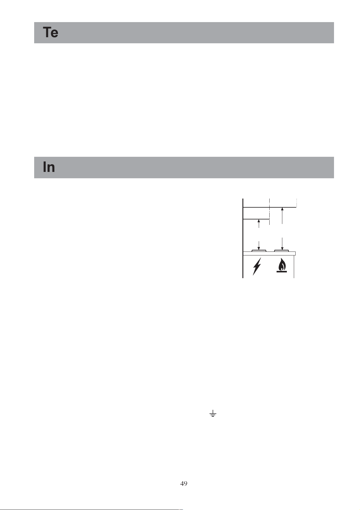
electric hobs 500 mm
gas hobs 650 mm
The hood can be installed above these heights
but for optimum performance it should be
installed at the distance quoted for the
appropriate heat source.
The national Standard on fuel-burning systems
specifies a maximum depression of 0.04 mbar in
such rooms.
The air outlet must not be connected to chimney
flues or combustion gas ducts. The air outlet
must under no circumstances be connected to
ventilation ducts for rooms in which fuel-burning
appliances are installed.
The air outlet installation must comply with the
regulations laid down by the relevant authorities.
When the unit is used in its extractor version, a
sufficiently large ventilation hole must be
provided, with dimensions that are approximately the same as the outlet hole.
National and regional building regulations
impose a number of restrictions on using hoods
and fuel-burning appliances connected to a
chimney, such as coal or oil room-heaters and
gas fires, in the same room.
Hoods can only be used safely with appliances
connected to a chimney if the room and/or flat
(air/environment combination) is ventilated from
outside using a suitable ventilation hole approximately 500-600 cm2 large to avoid the
possibility of a depression being created during
operation of the hood.
If you have any doubts, contact the relevant
controlling authority or building inspectors
office.
Since the rule for rooms with fuel burning
appliances is outlet hole of the same size as the
ventilation hole, a hole of 500-600 cm2, which
is to say a larger hole, could reduce the performance of the extractor hood.
If the hood is used in its filtering function, it will
operate simply and safely in the above
conditions without the need for any of the
aforementioned measures.
When the hood is used in its extractor function,
the following rules must be followed to obtain
optimal operation:
short and straight outlet hose
keep bends in outlet hose to a minimum
never install the hoses with an acute angle,
they must always follow a gentle curve.
keep the hose as large as possible
(preferably the same diameter as the
outlet hole).
Failure to observe these basic instructions will
drastically reduce the performance and increase
the noise levels of the extractor hood.
For the user
The cooker hood is designed to extract
unpleasant odours from the kitchen, it will not
extract steam.
Always cover lighted elements, to prevent
excess heat from damaging the appliance. In
the case of oil, gas and coal fired cookers it is
essential to avoid open flames.
Also, when frying, keep the deep frying pan on
the cooker top/cooker under careful control.
The hot oil in the frying pan might ignite due to
overheating.
The risk of self-ignition increases when the oil
being used is dirty.
It is extremely important to note that
overheating can cause a fire.
Never carry out any flambé cooking under
the hood.
Always disconnect the unit from the power
supply before carrying out any work on the
hood, including replacing the light bulb
(take the cartridge fuse out of the fuse holder or
switch off the automatic circuit breaker).
It is very important to clean the hood and
replace the filter at the recommended
intervals. Failure to do so could cause
grease deposits to build up, resulting in a
fire hazard.
The appliance is not intended for use by young
children or infirm persons without supervision.
Young children should be supervised to ensure
that they do not play with the appliance.
WARNING - Ensure that the appliance is
39
switched off before replacing the lamp to avoid
the possibility of electric shock.
Page 4
Description of the Appliance
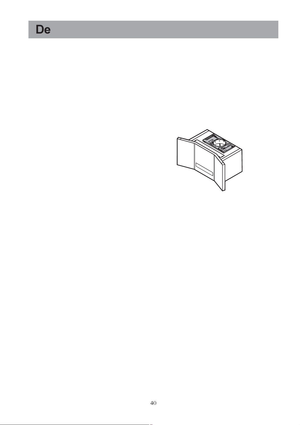
The hood is supplied as an extractor unit and
can also be used with a filtering function by
fitting one charcoal filter.
You will need an original charcoal filter for this
function (Available from your local Service
Force Centre).
Extractor version
In this version fumes are extracted to the
outside via a hose connected to the coupling ring
A. Fig. 1.
In order to obtain the best performance the hose
should have a diameter equal to the outlet hole.
Should there already be a pipe of diameter 125
or 120 mm that ducts to the outside through the
walls, it is possible to use the 150/125-120 mm
reduction flange provided.
In this case the hood will be slightly noisier.
Fig. 1
A
Filter Version
The air is filtered through an charcoal filter and
returned to the kitchen through the top grill of
the outlet pipe.
You will need an original charcoal filter for the
filtering function. (See Special Accessories).
40
Page 5
Control Panel
Best results are obtained by using a low speed for normal conditions and a high speed when odours are more
concentrated.
Turn the hood on a few minutes before you start cooking, you will then get an under pressure in the kitchen.
The hood should be left on after cooking for about 15 minutes or until all the odours have disappeared. The
control switches are located on the units front panel:
3
ab
Fig. 2
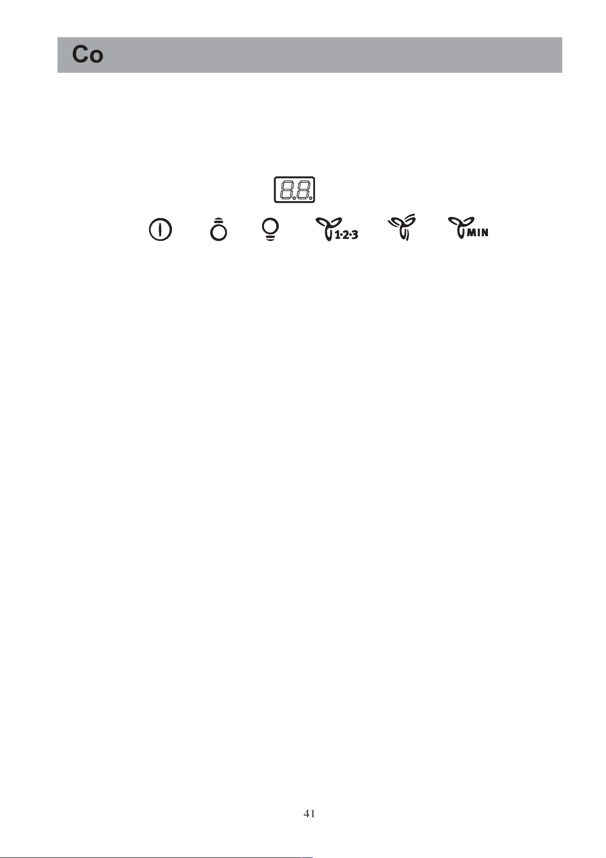
1 - Mains switch, ON/OFF
Press for less than 1 1/2 seconds and the cooker hood goes into the "stand by" position (point "b" is
illuminated).
Press for more than 1 1/2 seconds and the cooker hood turns OFF, ALL the controls (except the light push
button) are disabled (the display is off).
Press again for more than 1 1/2 seconds to reset the cooker hood to "stand by".
2.1 - ON/OFF illumination switch: lower lights
2.2 - ON/OFF illumination switch: upper and lateral lights
3 - Display
4 - Start and choice of motor speed 1-2-3-1-2.........
5 - Intensive speed on/off. The Intensive speed runs for 5 minutes:
If the hood is on when the Intensive speed is activated, the hood will revert to previous speed after 5
minutes.
If the hood is off when the Intensive speed is activated, the hood will automatically turn off after 5 minutes.
To interrupt the Intensive speed, press button 1 or 4.
The letter P appears on the display and the remaining time (the point a is flashing), if interrupted an
acoustic signal is heard.
6 - Self-Timer: times all the speed levels (the point b is flashing), and then the cooker hood switches off:
The self-timer is set as follows:
st
1
speed level 20 minutes
nd
2
speed level 15 minutes
rd
3
speed level 10 minutes
The display shows the remaining operation time, at the end of the time an acoustic signal is heard.
Depressing the push-button again exits the function.
1 2.1
2.2
45 6
Should the hood or the controls fail to operate: disconnect the power supply for at least 5 seconds. After
reconnecting the power supply wait 15 seconds and then check that the cooker hood is now operating correctly.
41
Page 6

Grease and charcoal filter maintenance
indicator
This hood is fitted with a device that indicates
when it is necessary to clean the grease filter or
the charcoal filter (if the hood is used in the
recirculation version with a charcoal filter).
On delivery, the hood is not supplied with a
charcoal filter, so the saturation indicator will be
disabled.
If the hood is to be used with a charcoal filter, the
saturation
indicator light must be enabled as follows:
Set the hood OFF.
Press buttons 4 and 5 simultaneously and hold
them for 3 seconds. At first only the grease filter
LED F will light up, but when the charcoal filter
LED C lights up the saturation indicator will be
enabled.
To disable it: Press buttons 4 and 5 again
simultaneously and hold them for 3 seconds, until
the charcoal filter LED C goes out.
Grease filter LED (F)
LED F will start to flash when it is time to clean
the grease filter.
Cleaning will be necessary after 40 working hours.
Always comply with the maintenance instructions
for the grease filter.
Charcoal filter LED (C)
The charcoal filter LED C will start to flash when
the charcoal filter needs to be replaced.
This operation is necessary after approximately 160
working hours.
Resetting the saturation indicator
After cleaning or replacing the filters, press button
1 for 3 seconds until the grease filter LED F or the
charcoal filter LED C stops flashing.
Warning! The resetting of the saturation indicator
MUST be done in stand-by, never disconnect the
hood from the mains.
Correct ventilation
If the cooker hood is to work correctly there must
be an under pressure in the kitchen. It is important
to keep the kitchen windows closed and have a
window in an adjacent room open.
42
Page 7
Maintenance and Care
The hood must always be disconnected from the electricity supply before beginning any
maintenance work.
Cleaning the hood
Clean the outside of the hood using a damp
cloth and a mild detergent.
Never use corrosive, abrasive or flammable
cleaning products.
Never insert pointed objects in the motors
protective grid.
Wash the outside surfaces using a delicate
detergent solution. Never use caustic detergents
or abrasive brushes or powders.
Only ever clean the switch panel and filter grille
using a damp cloth and delicate detergents.
It is extremely important to clean the unit and
change the filters at the recommended intervals.
Failure to do so will cause grease deposits to
build up that could constitute a fire hazard.
Metal grease filter
The purpose of the grease filters is to absorb
grease particles which form during cooking and
it must always be used, either in the external
extraction or internal recycling function.
Attention: the metal grease filters must be
removed and washed, either by hand or in the
dishwasher, every four weeks.
Removing the metal grease filter
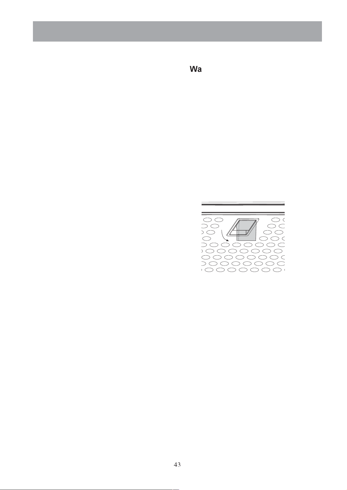
Pull the handle downwards, then remove the
filter. Fig. 3.
Hand washing
Soak grease filters for about one hour in hot
water with a little washing-up liquid, then rinse
off thoroughly with hot water. Repeat the
process if necessary. Refit the grease filters
when they are dry.
Dishwasher
Place grease filters in the dishwasher. Select
most powerful washing programme and highest
temperature, at least 65°C. Repeat the process.
Refit the grease filters when they are dry.
When washing the metal grease filter in the
dishwasher a slight discolouration of the filter
can occur, this does not have any impact on its
performance.
Clean the inner housing using a hot detergent
solution only (never use caustic detergents,
abrasive powders or brushes).
Warning
Failure to observe the instructions on cleaning
the unit and changing the filters will cause a fire
hazard. You are therefore strongly
recommended to follow these instructions.
The manufacturer declines all responsibility for
any damage to the motor or any fire damage
linked to inappropriate maintenance or failure to
observe the above safety recommendations..
Fig. 3
43
Page 8
Charcoal filter
The charcoal filter should only be used if you
want to use the hood in the recirculation
function.
To do this you will need an original charcoal
filter (available from your local Service Force
Centre).
Replacing the charcoal filter
The charcoal filter cannot be washed nor
regenerated.
The charcoal filter should be replaced every 4
months under normal use.
Replacement filters are available from your
local Service Force Centre.
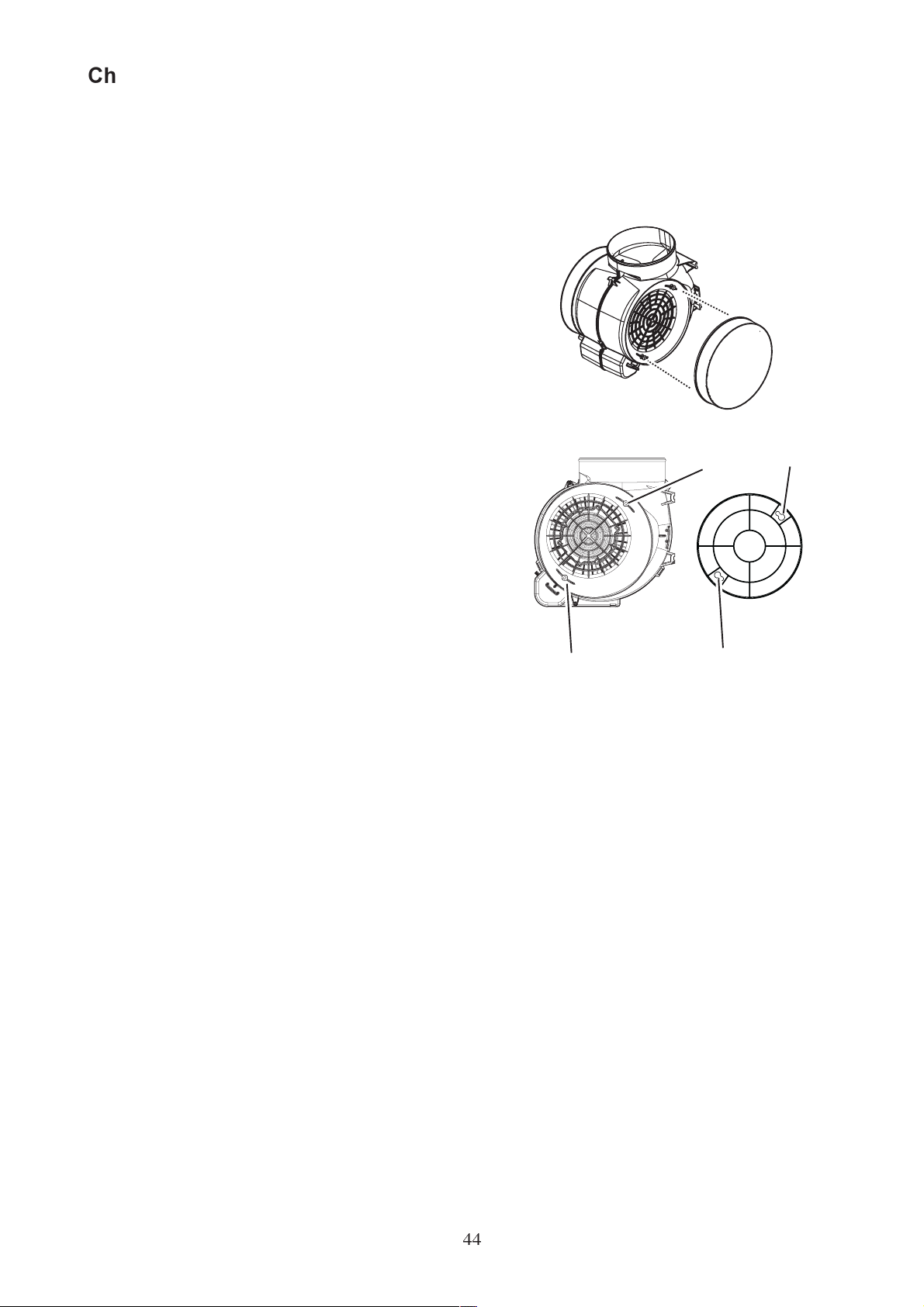
Fitting - Fig. 4
Fit the filter/s over the motor.
Align the pins R on the cowl with the slots S,
then turn the filter clockwise until it locks in
place.
To remove proceed in the reverse order.
Always specify the hood model code number
and serial number when ordering replacement
filters. This information is shown on the
registration plate located on the inside of the
unit.
The charcoal filter can be ordered from your
local Service Force Centre.
R
S
Fig. 4
R
S
44
Page 9
Changing the light bulb
Disconnect the cooker hood from the
mains supply.
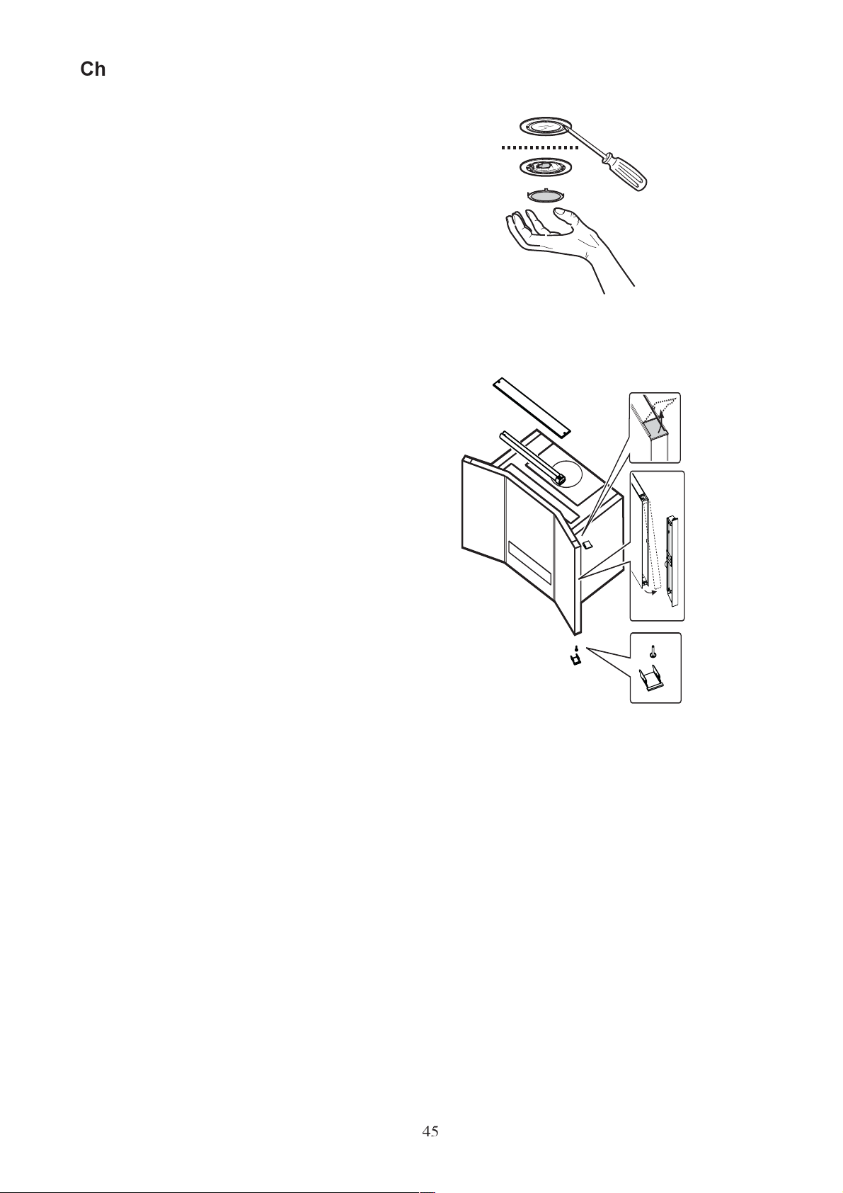
Lower light(s) Fig. 5
20W max halogen lamp (G4)
Raise the overhead light and remove it using a
screwdriver Fig. 5.
Extract the damaged lamp and replace it with
another of an equivalent type.
Lateral light(s) Fig. 6
Attention! To guarantee the same quality of
illumination, we advise using the same type of
lamp: Philips neon lamp of 8Watt max (G5) Ref.
Code 8711500644275.
Take care that the transparent side of the lamp is
facing outwards to guarantee a correct diffusion of
the illumination.
Lamps of different producers can be used as long
as they have the same technical characteristics.
Release the two tabs at the sides (upper and
lower spring attachment/release) of the
overhead light. If necessary lever with a small
screwdriver taking care not to damage the
glass.
Unscrew the screw that fixes the overhead
light.
Extract the lamp-holder from below and release
it from the attachment point above.
Remove the lamp and replace it with a new one
of equivalent type.
Replace the Starter if necessary (bayonet
fixture).
Fig. 5
Fig. 6
Upper light(s) Fig. 6
36W max PL lamp (2G11)
Remove the overhead light unscrewing the
two lateral screws.
Pull the lamp to release it from its seat.
Extract the damaged lamp and replace it with
another of an equivalent type.
Replace the Starter if necessary (bayonet
fixture).
Remount the overhead light.
Before contacting the assistance service
because the lamp does not switch on, check
that it is inserted correctly.
45
Page 10
What to do if
If your appliance fails to work properly please carry out the following checks.
Symptom Solution
The cooker hood will not start... Check that: The hood is connected to the electricity supply.
Check that a fan speed has been selected
The cooker hood is not working Check that: The fan speed is set high enough for the task.
The grease filters are clean.
The kitchen is adequately vented to allow the entry of fresh air.
If set up for recirculation, check that the charcoal filter is still effective.
If set up for extraction, check that the ducting and outlets are not
blocked.
The cooker hood has The safety cut-out device has been tripped.
switched off during operation... Turn off the hob and then wait for the device to reset.
If the hood has been installed below the heights indicated in the
installation instructions the motor will cut-out frequently which will
damage the hood.
If after all these checks, the problem persists, contact your local Service Force Centre, quoting the model and
serial number.
Please note that it will be necessary to provide proof of purchase for any in-guarantee service calls.
In-guarantee customers should ensure that the above checks have been made as the engineer will make a
charge if the fault is not a mechanical or electrical breakdown.
Special Accessories
Charcoal Filter Type 29
Inox Telescopic chimney (for extraction mode only) E-Nr. 942 120 750
46
Page 11

Technical assistance service
You are welcome to telephone our technical assistance service (see list of technical assistance centres)
whenever you need information or in the unlikely event of a fault.
For service in Australia call 1300 650 020.
When calling, please be ready to specify:
1. The model code number
2. The serial number (E-Nr.)
3. The manufacturing number (F-Nr.)
This information is shown on the registration plate inside the unit behind the grease filter.
We reserve the right to change specifications and colours as a result of our policy of continuing technological
development.
Service and Spare Parts
In the event of your appliance requiring service, or if you wish to purchase spare parts, contact your local
Service Force Centre by telephoning: 08705 929 929
Your call will be automatically routed to the Service Centre covering your post code area. For the address of
your local Service Force Centre and further information about Service Force, please visit the website at
www.serviceforce.co.uk
Please ensure that you have read the section What to do if.... as the engineer will make a charge if the fault is
not a mechanical or electrical breakdown even the appliance is under warranty. Please note that proof of
purchase is required for in-guarantee service calls.
Help us to help you
Please determine your type of enquiry before writing or telephoning.
When you contact us we need to know:
Your name Clear and concise details of the fault
Address and post code Name and model of the appliance*
Telephone number E number*
Serial number*
* This information can be found on the rating plate, which can be seen when the grease filters are removed.
If you require Customer Service in the Republic of Ireland please contact us at the address below:
Electrolux
Electrolux Group (Ire) Ltd
Long Mile Road
Dublin 12
Republic of Ireland
Tel: + 353 (0) 1 4090751
Email: [email protected]
CUSTOMER CARE DEPARTMENT
For general enquiries concerning your AEG appliance or for further information on ELECTROLUX products,
please contact our Customer Care Department by letter or telephone at the address below or visit our website at
www.electrolux.co.uk
Customer Care Department
Electrolux
55-77 High Street
Slough, Berkshire
SL1 1DZ
08705 950950 (*)
* calls to this number may be recorded for training purposes.
47
Page 12

Guarantee Conditions
Standard guarantee conditions
We, Electrolux, undertake that if within 12 months of the date of the purchase this Electrolux appliance or any
part thereof is proved to be defective by reason only of faulty workmanship or materials, we will, at our option
repair or replace the same FREE OF CHARGE for labour, materials or carriage on condition that:
The appliance has been correctly installed and used only on the electricity supply stated on the rating plate.
The appliance has been used for normal domestic purposes only, and in accordance with the manufacturers
instructions.
The appliance has not been serviced, maintained, repaired, taken apart or tampered with by any person not
authorised by us.
All service work under this guarantee must be undertaken by an Electrolux Service Force Centre. Any appliance
or defective part replaced shall become the Companys property.
This guarantee is in addition to your statutory and other legal rights.
Home visits are made between 8.30am and 5.30pm Monday to Friday.
Visits may be available outside these hours in which case a premium will be charged.
Exclusions
This guarantee does not cover:
Damage or calls resulting from transportation, improper use or neglect, the replacement of any light bulbs or
removable parts of glass or plastic.
Costs incurred for calls to put right an appliance which is improperly installed or calls to appliances outside the
European Community (EC) or European Free Trade Area.
Appliances found to be in use within a commercial environment, plus those which are subject to rental
agreements.
Products of Electrolux manufacture which are not marketed by Electrolux.
European Guarantee
If you should move to another country within Europe then your guarantee moves with you to your new home
subject to the following qualifications:
The guarantee starts from the date you first purchased your product.
The guarantee is for the same period and to the same extent for labour and parts as exists in the new country of
use for this brand or range of products.
This guarantee relates to you and cannot be transferred to another user.
Your new home is within the European Community (EC) or European Free Trade Area.
The product is installed and used in accordance with our instructions and is only used domestically, i.e. a normal
household.
The product is installed taking into account regulations in your new country.
Before you move please contact your nearest Customer Care centre, listed below, to give them details of your
new home. They will then ensure that the local Service Organisation is aware of your move and able to look
after you and your appliances.
France Senlis +33 (0)3 44 62 20 13
Germany Nürnberg +49 (0)800 234 7378
Italy Pordenone +39 (0) 800 117511
Sweden Stockholm +46 (0)20 78 77 50
UK Slough +44 (0) 1753 219898
48
Page 13
Technical Specifications
Model EFC 9490
Dimensions (in cm):
Height: 38,5
Width: 80
Depth: 42,5
Maximum absorbed power: 275 W
Motor absorption: 180 W
Upper light(s): 1 x 36 W
Lower light(s): 2 x 20 W
Lateral light(s): 2 x 8 W
Length of the cable: 150 cm
Electrical connection: 220-240 V
Subject to change without notice.
Installation
Unpacking
Check that the cooker hood has no damages.
Transportation damages should immediately be
reported to the company responsible for the
transportation.
Damages, faults and eventually missing details should
immediately be reported to the retailer.
Take care of the packing materials so that small
children cannot play with them.
Min
50 cm
Min
65 cm
Fitting
The hood is to be mounted on the wall.
When installed, the hood must be not less than 50 cm.
above electric burners or 65 cm. above gas or mixedfuel burners.
The hood can be installed above these heights but for
optimum performance it should be installed at the
distance quoted for the appropriate heat source.
Electrical connection (not for UK)
Safety warnings for the electrician
Before connecting the appliance to the power supply,
check that the voltage indicated on the rating plate
corresponds to the mains power supply available.
Appliances fitted with a plug can be connected to any
standard power socket within easy access.
Should it be necessary to provide a fixed connection,
the hood must only be installed by an electrician
authorised by the local electricity board. When
installing, an omnipolar disconnector with a distance
of at least 3 mm between contacts must be provided.
Fixed connection of the appliance must only be
carried out by an authorised electrician.
Fig. 7 - Fitting
Electrical connection for UK
only
Safety warnings for the electrician
Connect the hood to the mains supply via a double
pole switch which has 3 mm minimum separation
between the contacts.
The switch must be accessible at all times.
The following is valid in the United Kingdom only:
- the wire which is coloured green and yellow
must be connected to the terminal which is
marked with the letter E or by the earth symbol
( ), or coloured green or green and yellow;
- the wire which is coloured blue must be
connected to the terminal which is marked with
the letter N or coloured black, -
- the wire which is coloured brown must be
connected to the terminal which is marked with
the letter L or coloured red.
49
Page 14
Installation
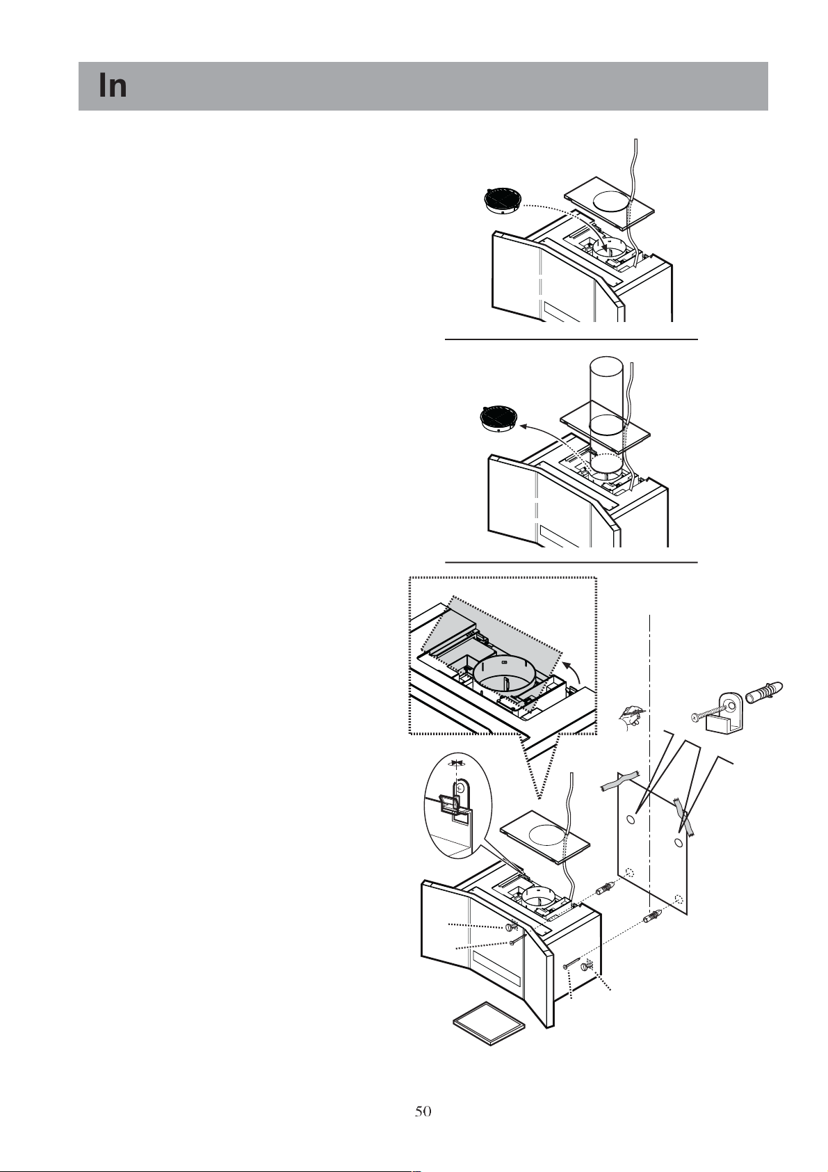
Mounting accessories included
4 wall plugs Ø 8 mm (brick fixing only)
4 wood-screws 5 x 45 mm
2 hooks
1 allen spanner
Wall unit mounting - Fig. 8
Trace the symmetry axis, position the
perforation template (1) on the wall and mark
the two holes to make, then make the holes (2 x
Ø 8 mm) (2).
Insert the two dowels into the wall with hooks
(3).
Open the upper cover temporarily to get to the
hooking area of the hood (4).
If you want to install a telescopic flue (to order,
see special accessories), the upper cover must
be completely removed (in this case release the
electrical cable and the core hitch from the
cover).
Attach the hood and adjust its horizontally using
the adjustment screws (5).
Remove the metal filters (6) and mark two
holes on the wall (7). Release the hood and
make the two holes previously marked (2 x Ø 8
mm).
Insert the wall dowels into the two holes (8)
and hang the hood up again; adjust it using the
screws (9) and fix the hood definitively with the
supplied screws (10).
Aspiration version (S):
a. if installed, remove the deflector from the
exit hole (11a).
b. insert the tube between the exit hole and the
wall drawer or the attachment to the wall/
ceiling (11b).
Filtering Version (K): if not already installed,
apply the deflector as cover of the exit hole
(11c).
Put the upper cover back in its place again.
Connect the electrical connection (12) (see
Electrical connection chapter).
9
10
K
S
11c
11b
11a
4
1
2+3
5
12
4
7
7
8
8
50
6
Fig. 8
10
9
Page 15

The Electrolux Group. The world´s No.1 choice.
The Electrolux Group is the world´s largest producer of powered appliances for kitchen, cleaning and outdoor use. More than 55 million Electrolux
Group products (such as refrigerators, cookers, washing machines,vacuum cleaners, chain saws and lawn mowers) are sold each year to a value
of approx. USD 14 billion in more than 150 countries around the world.
© Electrolux 2003
LI2KF A Ed. 03/05
 Loading...