

Page 1
USER MANUAL
EFC9360
Page 2

We were thinking of you
when we made this product
Page 3
electrolux 3
DE
EMPFEHLUNGEN UND HINWEISE 6
CHARAKTERISTIKEN 7
MONTAGE 9
BEDIENUNG 12
WARTUNG 13
IT
CONSIGLI E SUGGERIMENTI 26
CARATTERISTICHE 27
INSTALLAZIONE 29
USO 32
MANUTENZIONE 33
FR
CONSEILS ET SUGGESTIONS 16
CARACTERISTIQUES TECHNIQUES 17
INSTALLATION 19
UTILISATION 22
ENTRETIEN ET NETTOYAGE 23
EN
RECOMMENDATIONS AND SUGGESTIONS 36
CHARACTERISTICS 37
INSTALLATION 39
USE 42
MAINTENANCE 43
Page 4
4 electrolux
DE
Willkommen bei Electrolux!
Wir möchten uns bedanken, dass Sie
sich für ein erstklassiges Produkt von
Electrolux entschieden haben, welches
Ihnen sicherlich viel Freude bereiten
wird. Es ist unser Bestreben, eine breite
Vielfalt von Qualitätsprodukten anzubieten, die helfen, Ihr Leben etwas komfortabler zu machen. Sie fi nden einige
Beispiele auf der vorletzten Seite in diesem Heft. Bitte nehmen Sie sich einige
Minuten, diese Benutzerinformation zu
lesen, um voll von den Vorteilen Ihres
neuen Gerätes profi tieren zu können.
Wir sind sicher, dass wird Ihr Leben
zukünftig etwas leichter machen.
Wir wünschen eine gute Zeit.
IT
Egregio Cliente,
Complimenti per aver scelto un elettrodomestico Electrolux che, siamo
certi, avrà modo di apprezzare per le
prestazioni, la qualità e l’affi dabilità e
che le renderà la vita di ogni giorno più
confortevole, facile e sicura.
Da sempre il nostro impegno è quello
di produrre utilizzando la tecnologia più
avanzata, nel rispetto dell’ambiente e
sempre in anticipo rispetto agli obblighi
normativi.
Oltre il 90% dei nostri elettrodomestici
sono prodotti ecologici in classe A,
A+, A++ e vengono raccomandati dal
WWF.
La lettura completa di questo libretto le
permetterà un utilizzo corretto e sicuro
della sua apparecchiatura e le darà
anche utili consigli sulla manutenzione
più effi ciente.
FR
Bienvenue dans le monde
d’Electrolux
Nous vous remercions de la confi ance
que vous nous témoignez en choisissant un appareil Electrolux qui, nous
espérons vous accompagnera agréablement au fi l du temps.
Au travers d’une large gamme
de produits de qualité, la volonté
d’Electrolux est de vous rendre la vie
plus agréable.
Vous pouvez en voir quelques exemples sur la couverture de cette notice.
Nous vous invitons à prendre quelques
minutes pour découvrir ce guide qui
vous permettra de profi ter au mieux de
tous les avantages de votre nouvel appareil.
Nous vous assurons que son utilisation
vous offrira jour après jour satisfaction
et sérénité.
A bientôt.
EN
Welcome to the world of Electrolux
Thank you for choosing a fi rst class
product from Electrolux, which hopefully will provide you with lots of pleasure
in the future. The Electrolux ambition is
to offer a wide variety of quality products that make your life more comfortable. You fi nd some examples on the
cover in this manual. Please take a few
minutes to study this manual so that
you can take advantage of the benefi ts
of your new machine. We promise that
it will provide a superior User Experience delivering Ease-of-Mind.
Good luck!
Page 5

electrolux 5
Page 6
Empfehlungen und Hinweise electrolux 6
EMPFEHLUNGEN UND HINWEISE
MONTAGE
• Das Gerät darf nur vom Fachpersonal
angeschlossen werden.
• Der Hersteller haftet nicht für Schäden, die
auf eine fehlerhafte und unsachgemäße
Montage zurückzuführen sind.
• Der minimale Sicherheitsabstand zwischen Kochmulde und Haube muss 450
mm betragen.
• Prüfen, ob die Netzspannung mit dem
Wert auf dem im Haubeninneren angebrachten Schild übereinstimmt.
• Bei Geräten der Klasse I ist sicherzustellen, dass die elektrische Anlage des
Wohnhauses über eine vorschriftsmäßige
Erdung verfügt.
• Das Anschlussrohr der Haube zur Luftaustrittsöffnung sollte möglicherweise einen
Durchmesser von 150 mm aufweisen.
Der Rohrverlauf muss so kurz wie möglich
sein.
• Die Haube darf an keine Entlüftungsschächte angeschlossen werden, in die
Verbrennungsgase (Heizkessel, Kamine
usw.) geleitet werden.
• Werden im Raum außer der Dunstabzugshaube andere, nicht elektrisch betriebene
(z.B. gasbetriebene) Geräte verwendet,
muss für eine ausreichende Belüftung
gesorgt werden. Sollte die Küche diesbezüglich nicht entsprechen, ist an einer
Aussenwand eine Öffnung anzubringen,
die Frischluftzufuhr gewährleistet.
BEDIENUNG
• Die Dunstabzugshaube ist ausschließlich
zum Einsatz im privaten Haushalt und zur
Beseitigung von Küchengerüchen vorgesehen.
• Bei unsachgemäßer Benutzung wird keine
Haftung übernommen.
Achtung! Große Flammen bei einge-
schalteter Haube niemals unbedeckt
lassen.
• Die Intensivität der Flamme ist so zu regulieren, dass sie den Topfboden nicht
überragt.
Achtung! Frittiergeräte müssen während des Gebrauchs stets beaufsichtigt werden: Überhitztes Öl kann sich
entzünden.
• Keine fl ambierten Speisen unter der Ab-
zugshaube zubereiten: Brandgefahr.
• Die Dunstabzugshaube darf von Kindern
oder Personen, die hinsichtlich der Bedienung nicht unterwiesen wurden, keinesfalls verwendet werden.
WARTUNG
• Bevor Wartungsarbeiten durchgeführt
werden, muss die Stromzufuhr zur Haube
unterbrochen werden, indem der Stecker
gezogen oder der Hauptschalter abgeschaltet wird.
• Bei der Filterwartung müssen die vom
Hersteller empfohlenen Zeiträume zum
Austauschen der Filter genauestens eingehalten werden.
• Zur Reinigung der Haubenfl ächen Wir
empfehlen ein feuchtes Tuch und ein mildes Flüssigreinigungsmittel.
• Bitte keine Reinigungsmittel mit Scheuermittel verwenden. Die Oberfl äche wird
damit verkratzt.
Das Symbol
seiner Verpackung weist darauf hin,
dass dieses Produkt nicht als normaler
Haushaltsabfall zu behandeln ist, sondern
an einem Sammelpunkt für das Recycling
von elektrischen und elektronischen Geräten
abgegeben werden muss. Durch Ihren
Beitrag zum korrekten Entsorgen dieses
Produkts schützen Sie die Umwelt und die
Gesundheit Ihrer Mitmenschen. Umwelt
und Gesundheit werden durch falsches
Entsorgen gefährdet. Weitere Informationen
über das Recycling dieses Produkts erhalten
Sie von Ihrem Rathaus, Ihrer Müllabfuhr oder
dem Geschäft, in dem Sie das Produkt
gekauft haben.
auf dem Produkt oder
DE
Page 7
7 electrolux Charakteristiken
CHARAKTERISTIKEN
Platzbedarf
DE
480
Min.920 - Max.1130
Page 8
Komponenten
Pos. St. Produktkomponenten
1 1 Haubenkörper mit Schaltern, Be-
leuchtung, Gebläsegruppe, Filter
2 1 Teleskopkamin bestehend aus:
2.1 1 oberer Kaminteil
2.2 1 unterer Kaminteil
9 1 Reduzierfl ansch ø 150-120 mm
10 1 Flansch mit Ruckstauklappe ø
150 mm
14.1 2 Verlängerung Luftaustritt-An-
schlussstück
15 1 Luftaustritt-Anschlussstück
Pos. St. Montagekomponenten
7.2.1 2 Befestigungsbügel oberer Ka-
minteil
7.3 1 Bügel für Anschlusshalter
11 6 Dübel
12a 6 Schrauben 4,2 x 44,4
12c 6 Schrauben 2,9 x 9,5
St. Dokumentation
1 Bedienungsanleitung
Charakteristiken electrolux 8
15
14.1
7.3
10
9
2.1
2
2.2
1
7.2.1
12c
11
12a
DE
1112a
Page 9
9 electrolux Montage
MONTAGE
Bohren der Befestigungslöcher
und Fixieren der Befestigungsbügel
DE
Nachstehende Linien an die Wand
zeichnen:
• eine vertikale Linie bis zur Decke oder
oberen Begrenzung, und zwar in der
Mitte des Bereiches, in dem die Haube montiert werden soll;
• eine horizontale Linie: mit einem mi-
nimalen Abstand von 1040 mm zur
Kochfl äche.
• Einen Bügel 7.2.1 zirka 1-2 mm unter
der Decke oder oberen Begrenzung
an die Wand legen und seinen Mittelpunkt (Einschnitte) auf die vertikale
Bezugslinie ausrichten.
• Die Mitte der beiden Bügellöcher an
der Wand markieren.
• Den zweiten Bügel 7.2.1 an die Wand
legen, wobei ein Abstand X mm vom
oberen Bügel einzuhal-ten ist (X =
Höhe des jeweiligen oberen Kaminteils); den Mittelpunkt (Einschnitte) auf
die vertikale Bezugslinie ausrichten.
• Die Mitte der Bügellöcher an der Wand
markieren.
• Wie beschrieben einen Bezugspunkt
116 mm von der vertikalen Bezugslinie kennzeichnen.
• Gleichermaßen an der gegenüberliegenden Seite vorgehen.
• Mit einem Bohrer ø 8 mm die markierten Punkte bohren.
• Die Dübel 11 in die Bohrungen einfügen.
• Den unteren Bügel mit den mitgelieferten Schrauben 12a (4,2 x 44,4) fi -
xieren.
• Den Bügel für Anschlusshalter mit den
2 mitgelieferten Schrauben 12a (4,2 x
44,4) auf den oberen Bügel 7.2.1 befestigen.
• 2 der mitgelieferten Schrauben 12a
(4,2 x 44,4) bei den Befestigungslöchern des Haubenkörpers einschrauben, wobei zwischen Wand und
Schraubenkopf ein Freiraum von 5-6
mm zu belassen ist.
7.2.1
11
12a
450 mm min
116
1÷2
X
116
1040
Page 10
Montage des Haubenkörpers
• Bevor der Haubenkörper eingehakt
wird, die 2 Schrauben Vr bei den Haubenkörper-Anhakpunkten festziehen.
• Den Haubenkörper bei den Schrauben
12a einhängen.
• Die Halteschrauben 12a defi nitiv fest-
ziehen.
• Den Haubenkörper mit Hilfe der Schrauben Vr ausrichten.
Anschluss in Abluftversion
Bei Abluftbetrieb kann die Haube vom
Installateur wahlweise mittels Rohr oder
Schlauch (ø150 oder 120mm) an die Außenrohrleitung angeschlossen werden.
Anschlussrohres ø 150
• Den Flansch mit Ruckstauklappe 10
anbringen.
• Das Rohr mit geeigneten Rohrschellen
fi xieren.Das hierzu erforderliche Material
wird nicht mitgeliefert.
Anschlussrohres ø 120
• Bei Verwendung eines Anschlussrohres
ø 120 den Reduzierfl ansch 9 am Flansch
mit Ruckstauklappe 10 anbringen.
• Das Rohr mit geeigneten Rohrschellen
fi xieren.Das hierzu erforderliche Material
wird nicht mitgeliefert.
• Eventuell vorhandene Aktivkohlefi lter
entnehmen.
Montage electrolux 10
Vr
DE
12a
ø 120ø 150
10
9
10
Anschluss in Umluftversion
• Die Verlängerungen 14.1 beim Anschluss 15 seitlich einfügen.
• Den Anschluss 15 am Haltebügel 7.3
einsetzen und mit einer Schraube fi xie-
ren.
• Überprüfen, ob die Verlängerungen
14.1 mit den entsprechen-den Kaminstutzen sowohl horizontal wie auch vertikal über-einstimmen.
• Vom Installateur wahlweise mittels Rohr
oder Schlauch (ø 150 mm), den Anschluss 15 am Haubenaustritt anbringen.
• Kontrollieren, ob der Aktivkohle-Geruchsfi lter montiert ist.
14.1
15
ø 150
Page 11
11 electrolux Montage
Elektroanschluss
• Bei Anschluss der Haube an das
Stromnetz muss ein zweipoliger
Schalter mit einem Öffnungsweg von
mindestens 3 mm zwischengeschal-
DE
tet werden.
• Entfernen Sie die Fettfi lter (s. Ab-
schnitt „Wartung“) und versichern Sie
sich, daß die Kabelverbindung in die
Steckdose des Gebläses einwandfrei
eingesteckt wird.
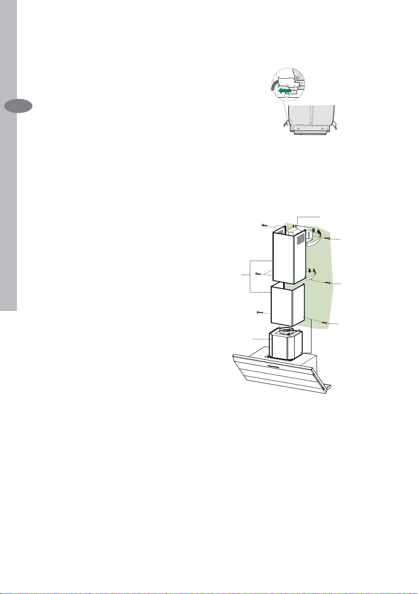
Kaminmontage
Oberer Kaminteil
• Die beiden seitlichen Schenkel leicht
auseinanderbiegen, hinter den Bügeln
7.2.1 einhängen und bis zum Anschlag wieder schließen.
• Bei den Bügeln 7.2.1 mit Hilfe der 4
mitgelieferten Schrauben 12c fi xie-
ren.
• Überprüfen, ob die Verlängerungen
mit den entsprechenden Kaminstutzen übereinstimmen.
Unterer Kaminteil
• Die beiden seitlichen Schenkel des
Kaminteils leicht auseinanderbiegen,
zwischen dem oberen Kaminteil und
der Wand einhängen und bis zum Anschlag wieder schließen.
• Den unteren Teil seitlich am Haubenkörper mit 2 der mitgelieferten Schrauben 12c fi xieren.
7.2.1
12c
2.1
2
12c
2.2
12c
1
Page 12
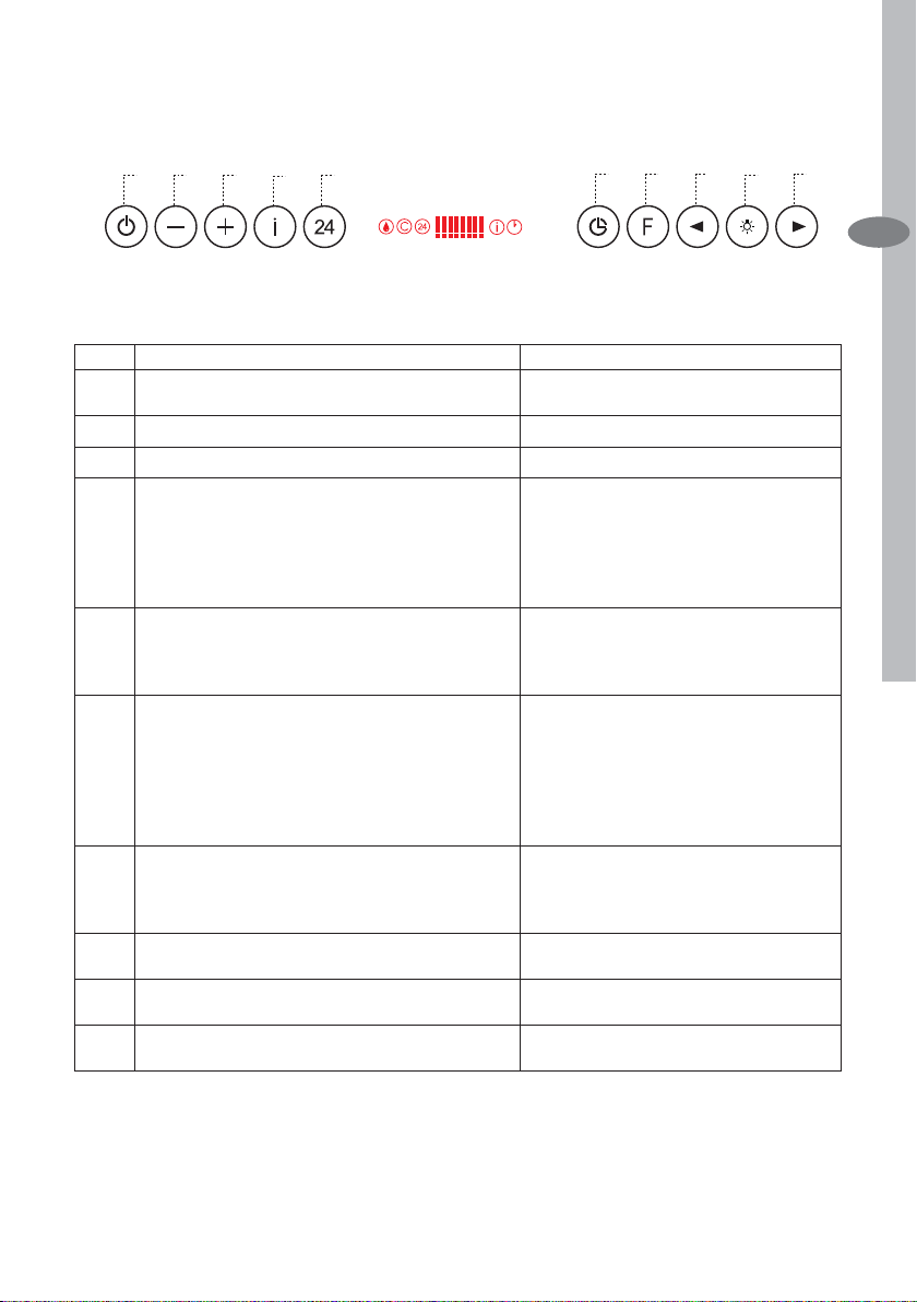
BEDIENUNG
Bedienung electrolux 12
F
A
B
C
E
D
G
Bedienfeld
Taste Funktion Display
Schaltet den Gebläsemotor in der zuletzt ver-wendeten
A
Gebläsestufe ein und aus.
Verringert die laufende Gebläsestufe. Die leuchtenden Segmente nehmen ab.
B
Aktiviert den Motor mit der ersten Gebläsestufe
C
Aktiviert die Intensivstufe bei jeder Geschwin-digkeit,
D
mit Ausnahme der Funktionen Delay und 24H. Die
Intensivstufe ist auf 10 Minuten begrenzt. Danach
kehrt das System zur zuvor eingestellten Gebläsestufe
zurück. Zum Besei-tigen sehr starker Küchendünste
geeignet.
Schaltet den Motor auf einer Gebläsestufe ein, die pro
E
Stunde ein zehnminütiges Absaugen von 100 m3/h
erlaubt. Danach schaltet sich der Motor aus.
Aktiviert das automatische Abschalten nach
F
30 Minuten. Zum Beseitigen von verbliebenen
Küchendünsten geeignet. Lässt sich nur bei
eingeschaltetem Motor und nicht bei Intensiv-stufe
oder 24-Stunden-Funktion aktivieren. Lässt sich durch
Drücken der Taste oder durch Ausschalten des Motors
deaktivieren.
Durch ca. 2 Sekunden langes Drücken der Taste wird
G
die Filtersättigungsanzeige rückgestellt.
Verringert die Intensität der Beleuchtung zyklisch mit
H
jedem Drücken der Taste.
Schaltet die Beleuchtungsanlage auf höchster
I
Intensitätsstufe ein und aus.
Steigert die Intensität der Beleuchtung zyklisch mit
L
jedem Drücken der Taste.
Zeigt die eingestellte Gebläsestufe an.
Die leuchtenden Segmente nehmen zu.
I blinkt und alle Segmente auf dem Display
leuchten.Lässt sich durch Drücken der Taste
ausschalten.
Zeigt 24 an und alle auf dem Display
angezeig-ten Segmente erlöschen allmählich
nacheinan-der.Lässt sich durch Drücken der
Taste ausschal-ten.
Zeigt das Symbol einer blinkenden Uhr
an.Lässt sich durch Drücken der Taste
ausschal-ten.
Nach 100 Betriebsstunden zeigt das Symbol
Tropfen die Sättigung der Metallfi lter an.Nach
200 Betriebsstunden zeigt C die Sättigung
der Aktivkohlefi lter an.
L
I
H
DE
Steuerbefehl Tastatursperre: Die Tastatur lässt sich, z.B. zur Reinigung der Scheiben, sperren, wenn Motor und Beleuchtung der Haube ausgeschaltet sind.Zum
Aktivieren oder Deaktivieren der Tastatursperre die Taste F (Delay) ca. 5 Sekunden
lang drücken. Der Vorgang wird immer durch einen Piepton und die Motorbalkenanzeige auf dem Display bestätigt.
Page 13
13 electrolux Wartung
WARTUNG
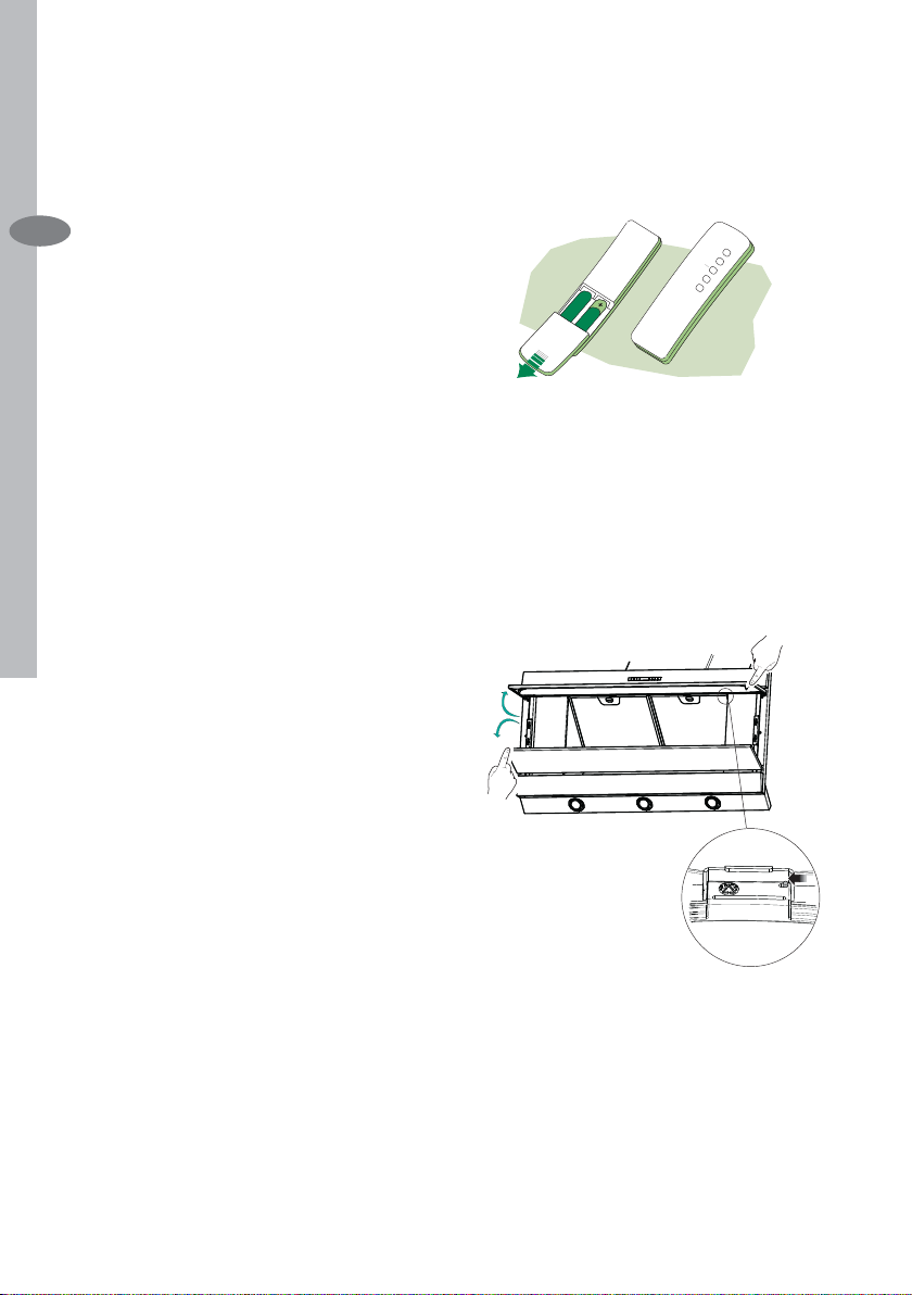
Fernbedienung (Option)
Dieses Gerät kann mit einer Fernbe-
DE
dienung gesteuert werden, welche mit
alkalischen Zink-Kohle-Batterien 1,5 V
des Standardtyps LR03-AAA versorgt
wird.
• Die Fernbedienung nicht in die Nähe
von Hitzequellen legen.
• Batterien müssen vorschriftsmäßig
entsorgt werden.
Reinigung der Comfort Panel
• Den Comfort Panel durch Ziehen öffnen.
• Die Platte vom Haubenkörper aushaken, indem der Hebel des Befestigungsstiftes verschoben wird.
• Die Comfort Panel darf keinesfalls im
Geschirrspüler gewaschen werden.
• Außen mit einem feuchten Lappen
und neutralem Flüssigreiniger säubern.
• Innen mit einem feuchten Lappen und
neutralem Reinigungsmittel säubern;
keine nassen Lappen oder Schwämme oder Wasserstrahl verwenden;
kein Scheuermittel verwenden.
• Am Ende die Platte wieder am Haubenkörper einhaken und schließen,
indem der Drehknopf in die dem Öffnen entgegengesetzte Richtung gedreht wird.
Page 14
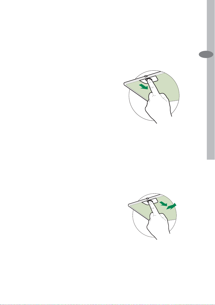
Selbsttragender Metallfettfi lter
reinigung
Die Filter können im Geschirrspüler ge-
reinigt werden und sollten gereinigt
werden, wenn das Symbol Tropfen
auf dem Display erscheint bzw. mindestens ca. alle 2 Monate oder bei
sehr intensivem Einsatz auch häufi -
ger.
Rückstellen der Sättigungsanzeige
• Die Taste G mindestens 2 Sekunden
lang drücken.
Filterreinigung
• Das Comfort Panel öffnen.
• Die Filter einzeln entnehmen, indem
sie zur Rücksei-te der Gruppe geschoben und gleichzeitig nach unten
gezogen werden.
• Die Filter waschen, darauf achten,
sie nicht zu ver-biegen und vor der
Remontage trocknen lassen. (Eine
eventuell im Lauf der Zeit auftretende
Verfärbung der Filteroberfl äche hat
keinerlei Einfl uss auf die Wirksamkeit
des Filters.)
• Bei der Remontage darauf achten,
dass sich der Griff an der sichtbaren
Außenseite befi ndet.
• Das Comfort Panel wieder schließen.
Wartung electrolux 14
DE
ACHTUNG: Bei der Version zu 60 cm
die Filter einen nach dem andern ausbauen, indem sie zunächst nach hinten
geschoben und gleichzeitig nach unten
und dann gegen die Mitte der Haube
gezogen werden.
Page 15
15 electrolux Wartung
Austauschen der AktivkohleFilter
Nicht waschbar und nicht regenerierbar.
Ersetzen, wenn das Symbol C auf dem
Display er-scheint bzw. mindestens alle
DE
4 Monate. Das Alarmsignal ist vorher zu
aktivieren.
Aktivierung/Deaktivierungder Sättigungsanzeige
• Bei Hauben in Umluftversion muss die
Aktivierung der Filtersättigungsanzeige bei der In-stallation oder danach
erfolgen.
• Die Beleuchtung und den Gebläsemotor abschalten.
• Die Taste E ca. 5 Sekunden lang gedrückt halten, bis die beiden letzten
Segmente und die ganze gepunktete
Linie der Motoranzeige auf dem Display aufl euchten.
• Die Taste E loslassen. Das Symbol
“Uhr” beginnt zu blinken.
• Innerhalb von 3 Sekunden die Taste
D zur Aktivierung / Deaktivierung der
Aktivkohlefi l-ter drücken.
• Bei Aufl euchten von Symbol C ist
die Aktivkohlefi lter-Sättigungsanzei-
ge AKTIVIERT.
• Bei Erlöschen von Symbol C ist die
Aktivkohlefilter-Sättigungsanzeige
DEAKTIVIERT.
Rückstellen der Sättigungsanzeige
• Die Beleuchtung und den Gebläsemotor abschalten.
• Die Taste G mindestens 2 Sekunden
lang drücken.
Filterwechsel
• Das Comfort Panel öffnen.
• Die Metallfettfi lter ausbauen.
• Den gesättigten Aktivkohle-Geruchsfi lter wie in der Zeichnung dargestellt
entfernen.
• Den neuen Filter an seinem Platz
montieren.
• Die Metallfettfi lter wieder montieren.
Auswechseln der Lampem
Halogenlampe 20 W
• Vor dem Auswechseln der Lampen,
die beiden Schrauben der Lampenhalterung loesen und die Lampenhalterung aus der Dunstabzugshaube
ziehen.
• Die Lampe aus der Halterung nehmen.
• Die Lampe durch eine gleichwertige
ersetzen und bei der Remontage darauf achten, daß die beiden Steckerstifte vorschriftsmäßig in die Lampenfassung eingeführt werden.
• Die Lampenhalterung wieder montieren, indem die beiden zuvor entfernten Schrauben wieder angezogen
werden.
Page 16

16 electrolux Conseils et Suggestions
CONSEILS ET SUGGESTIONS
INSTALLATION
• Le fabricant décline toute responsabilité en cas de dommage dû à une
FR
installa-tion non correcte ou non conforme aux règles de l’art.
• La distance minimale de sécurité entre le plan de cuisson et la hotte doit
être de 650 mm au moins.
• Vérifi er que la tension du secteur co-
rrespond à la valeur qui fi gure sur la
pla-quette apposée à l’intérieur de la
hotte.
• Pour les Appareils appartenant à la
Ière Classe, veiller à ce que la mise
à la terre de l’installation électrique
domestique ait été effectuée conformément aux normes en vigueur.
• Connecter la hotte à la sortie d’air aspiré à l’aide d’une tuyauterie d’un
diamètre égal ou supérieur à 120 mm.
Le parcours de la tuyauterie doit être
le plus court possible.
• Eviter de connecter la hotte à des
conduites d’évacuation de fumées
issues d’une combustion tel que
(Chaudière, cheminée, etc…).
• Si vous utilisez des appareils qui
ne fonctionnent pas à l’électricité
dans la pièce ou est installée la hotte
(par exemple: des appareils fonctionnant au gaz), vous devez prévoir
une aération suffi sante du milieu. Si la
cuisine en est dépourvue, pratiquez
une ouverture qui communique avec
l’extérieur pour garantir l’infi ltration de
l’air pur.
UTILISATION
• La hotte a été conçue exclusivement
pour l’usage domestique, dans le but
d’éliminer les odeurs de la cuisine.
• Ne jamais utiliser abusivement la hotte.
• Ne pas laisser les fl ammes libres à
forte intensité quand la hotte est en
ser-vice.
• Toujours régler les fl ammes de ma-
nière à éviter toute sortie latérale
de ces dernières par rapport au fond
des marmites.
• Contrôler les friteuses lors de
l’utilisation car l’huile surchauffée
pourrait s’enfl ammer.
• Ne pas préparer d’aliments fl am-
bés sous la hotte de cuisine : risque
d’incendie
• Cet appareil ne doit pas être utilisé par des personnes (y compris les
enfants) ayant des capacités psychiques, sensorielles ou mentales réduites, ni par des personnes n’ayant pas
l’expérience et la connaissance de ce
type d’appareils, à moins d’être sous
le contrôle et la formation de personnes responsables de leur sécurité.
• Les enfants doivent être surveillés
pour s’assurer qu’ils ne jouent pas
avec l’appareil.
ENTRETIEN
• Avant de procéder à toute opération
d’entretien, retirer la hotte en retirant
la fi che ou en actionnant l’interrupteur
général.
• Effectuer un entretien scrupuleux et
en temps dû des Filtres, à la cadence
conseillée.
• Pour le nettoyage des surfaces de la
hotte, il suffi t d’utiliser un chiffon humi-
de et détersif liquide neutre.
Le symbole sur le produit ou son
emballage indique que ce produit ne peut être
traité comme déchet ménager. Il doit plutôt
être remis au point de ramassage concerné,
se chargeant du recyclage du matériel
électrique et électronique. En vous assurant
que ce produit est éliminé correctement, vous
favorisez la prévention des conséquences
négatives pour l’environnement et la santé
humaine qui, sinon, seraient le résultat d’un
traitement inapproprié des déchets de ce
produit. Pour obtenir plus de détails sur le
recyclage de ce produit, veuillez prendre
contact avec le bureau municipal de votre
région, votre service d’élimination des
déchets ménagers ou le magasin où vous
avez acheté le produit.
Page 17

Caracteristiques Techniques electrolux 17
CARACTERISTIQUES TECHNIQUES
Encombrement
480
Min.920 - Max.1130
FR
Page 18

18 electrolux Caracteristiques Techniques
Composants
Réf. Q.té Composants de Produit
1 1 Corps de Hotte équipé de: Co-
mandes, Eclairage, Groupe Ven-
FR
tilateur, Filtres
2 1 Cheminée Télescopique formée
de :
2.1 1 Cheminée Supérieure
2.2 1 Cheminée Inférieure
9 1 Flasque de Réduction ø 150-120
mm
10 1 Buse avec clapet
14.1 2 Rallonge Raccord Sortie Air
15 1 Raccord Sortie Air
Réf. Q.té Composants pour l ’installa-
tion
7.2.1 2 Brides Fixation Cheminée
Supérieure
7.3 1 Bride Support Raccord
11 6 Chevilles
12a 6 Vis 4,2 x 44,4
12c 6 Vis 2,9 x 9,5
Q.té Documentation
1 Notice d’utilisation
15
14.1
7.3
10
9
2.1
2
2.2
1
7.2.1
12c
12a
1112a
11
Page 19

INSTALLATION
Installation electrolux 19
Perçage Paroi et Fixation Brides
Tracer sur la paroi:
• une ligne verticale allant jusqu’au plafond ou à la limite supérieure, au centre de la zone prévue pour le montage
de la hotte;
• une ligne horizontale à 1040 mm min.
au-dessus du plan de cuisson.
• Poser comme indiqué une bride 7.2.1
sur la paroi à 1-2 mm du plafond ou
de la limite supé-rieure, en alignant
son centre (découpes) sur la ligne verticale de repère.
• Marquer les centres des trous rainurés de la bride.
• Poser comme indiqué la bride 7.2.1
à X mm sous la première bride (X =
hauteur cheminée supérieure fournie),
en alignant son centre (découpes) sur
la ligne verticale de repère.
• Marquer les centres des trous rainurés de la bride.
• Marquer comme indiqué, un point de
référence à 116 mm de la ligne verticale de repère.
• Répéter cette opération sur le côté
opposé.
• Percer de ø 8 mm tous les points marqués.
• Insérer les chevilles 11 dans les trous.
• Fixer la bride inférieure 7.2.1 en utilisant les vis 12a (4,2 x 44,4) fournies.
• Fixer ensemble la bride supérieure
7.2.1 et le support 7.3 en utilisant les
vis 12a (4,2 x 44,4) fournies.
• Visser les 2 vis 12a (4,2 x 44,4) fournies dans les trous de fi xation du
corps hotte, en laissant un espace de
5-6 mm entre le mur et la tête de la
vis.
FR
7.2.1
11
12a
450 mm min
116
1÷2
X
116
1040
Page 20

20 electrolux Installation
Montage du Corps de la Hotte
• Avant d’accrocher le corps de la hotte,
serrer les deux vis Vr situées sur les
points d’accrochage du corps de la
hotte.
• Accrocher le corps de la hotte aux vis
FR
12a prévues à cet effet.
• Serrer défi nitivement les vis 12a de
support.
• Agir sur les vis Vr pour niveler le corps
de la hotte.
Sortie d’air en version évacuation
En cas d’installation en version aspirante,
brancher la hotte à la tuyauterie de sortie
via un tube ri-gide ou fl exible de ø 150 ou
120 mm, au choix de l’installateur.
Branchement avec un tube de ø150
• Insérer la buse avec clapet 10.
• Fixer le tube par des colliers appropriés. Le matériau nécessaire n’est pas
fourni.
Branchement avec un tube de ø120
• Insérer le fl asque de réduction 9 sur la
buse avec clapet 10.
• Fixer le tube par des colliers appropriés. Le matériau nécessaire n’est pas
fourni.
• Retirer les éventuels fi ltres anti-odeur
au charbon actif.
Vr
12a
ø 120ø 150
10
9
10
Sortie d’air version fi ltrante
• Insérer latéralement les rallonges raccord 14.1 sur le raccord 15.
• Placer le raccord 15 dans l’étrier de
soutien 7.3 en le fi xant avec une vis.
• S’assurer que la sortie des rallonges
raccord 14.1 se trouve au niveau des
bouches de la cheminée aussi bien en
horizontal qu’en vertical.
• Brancher le raccord 15 à la sortie du
corps de la hotte avec un tube rigide
ou fl exible de ø 150 mm, selon le choix
de l’installateur.
• S’assurer de la présence des fi ltres an-
ti-odeur au charbon actif.
14.1
15
ø 150
Page 21

Branchement Electrique
• Brancher la hotte sur le secteur en
interposant un interrupteur bipolaire avec ouverture des contacts d’au
moins 3 mm.
• Enlever les fi ltres à graisse (voir § “En-
tretien”) et s’assurer que le connecteur du câble d’alimentation soit bien
branché dans la prise du diffuseur.
Montage de la Cheminée
Cheminée supérieure
• Elargir légèrement les deux bords latériaux, et les accrocher derrières les
brides 7.2.1 ; refermer jusqu’à la butée.
• Fixer latéralement aux brides à l’aide
des 4 vis 12c fournies.
• S’assurer que la sortie des rallonges raccord se trouve au niveau des
bouches de la cheminée.
Cheminée inférieure
• Elargir légèrement les deux bords latériaux de la Cheminée et les accrocher entre la Cheminée supérieure et
la paroi; refermer jusqu’à la butée.
• Fixer latéralement la partie inférieure
au corps hotte, à l’aide des deux 2 vis
12c fournies.
Installation electrolux 21
FR
7.2.1
12c
2.1
2
12c
2.2
12c
1
Page 22

22 electrolux Utilisation
UTILISATION
A
B
C
E
D
FR
Tableau des commandes
Tasto Funzione Display
Accende e spegne il motore di aspirazione all’ultima
A
velocità utilizzata.
Decrementa la velocità di esercizio. Diminuiscono i segmenti accesi.
B
Incrementa la velocità di esercizio.
C
Attiva la velocità intensiva da qualsiasi velocità
D
ad eccezione del Delay e del 24H, tale velocità
è temporizzata a 10 minuti, al termine del tempo
il sistema ritorna alla velocità precedentemente
impostata. Adatta a fronteggiare le massime emissioni
di fumi di cottura.
Attiva il motore ad una velocità che consente
E
un’aspirazione di 100 m3/h per 10 minuti ogni ora,
terminati il motore si ferma.
Attiva lo spegnimento automatico ritardato di 30’.
F
Adatto per completare l’eliminazione di odori residui.
Attivabile solo a motore acceso ad una Velocità diversa
da 24H e Intensiva, si disattiva premendo il tasto o
spegnendo il motore.
Effettua il Reset dell’allarme saturazione Filtri premendo
G
il Tasto per circa 2 Secondi.
Decrementa l’intensità di Illuminazione ad ogni
H
pressione del Tasto in modo ciclico.
Accende e spegne l’impianto di illuminazione alla
I
massima intensità.
Incrementa l’intensità di Illuminazione ad ogni pressione
L
del Tasto in modo ciclico.
F
G
H
Visualizza la velocità impostata.
Aumentano i segmenti accesi.
Lampeggia I e i segmenti sul Display sono
tutti accesi.Si disattiva premendo il Tasto.
Visualizza 24 e i segmenti sul Display da
tutti accesi si spengono uno alla volta
ciclicamente.Si disattiva premendo il Tasto.
Visualizza il simbolo di un Orologio che
lampeggia.Si disattiva premendo il Tasto.
Dopo 100 ore di Funzionamento Visualizza il
simbolo Goccia per segnalare la saturazione
dei Filtri Metallici.Dopo 200 ore di
Funzionamento Visualizza C per segnalare
la saturazione dei Filtri al Carbone Attivo.
L
I
Commande de blocage du Clavier : il est possible de bloquer le clavier, par exemple
pour ef-fectuer le nettoyage des surfaces en verre quand le moteur et l’éclairage
de la hotte sont éteints. Appuyer sur la touche F (Retard) pendant env. 5 secondes
pour activer ou désactiver le blo-cage du clavier ; cette fonction est toujours confi r-
mée par un bip sonore et une animation qui s’affi che sur la barre du moteur.
Page 23

ENTRETIEN ET NETTOYAGE
Telecommande (Fournie sur Demande)
Il est possible de commander cet appareil au moyen d’une télécommande,
alimentée avec des piles alcalines zinccharbon 1,5 V du type standard LR03AAA.
• Ne pas ranger la télécommande à
proximité de sources de chaleur.
• Ne pas jeter les piles; il faut les déposer dans les récipients de récolte
spécialement prévus à cet effet.
Nettoyage des Confort Panel
• Ouvrir le Confort Panel, en tirant ce
dernier.
• Décrocher le panneau du corps de la
hotte, en faisant coulisser le levier du
goujon de fi xation spécialement pré-
vu.
• En aucun cas, le confort panel ne doit
être lavé au lave-vaisselle.
• Le nettoyer à l’extérieur à l’aide d’un
chiffon humide et d’un détergent liquide neutre.
• Le nettoyer également à l’intérieur,
en utilisant un chiffon humide et un
détergent neutre; ne pas utiliser des
chiffons ou des éponges mouillées,
ni des jets d’eau; ne pas utiliser des
substances abrasives.
• Lorsque l‘opération est achevée,
accrocher à nouveau le panneau sur
le corps de la hotte, puis le refermer,
en tournant le bouton dans le sens inverse par rapport à l’ouverture.
Entretien et Nettoyage electrolux 23
FR
Page 24

24 electrolux Entretien et Nettoyage
Filtres à graisse métalliques
Ils sont lavables même en lave-vaisselle
et doivent être lavés chaque fois que le
symbole Goutte s’affi che ou au moins
tous les 2 mois environ, voire plus sou-
FR
vent, en cas d’utilisation particulièrement intensive.
Rétablissement du signal d’alarme
• Appuyer sur la touche G pendant au
moins 2 se-condes.
Nettoyage des fi ltres
• Ouvrir le panneau Confort.
• Retirer les fi ltres, un à un, en les
poussant vers l’arrière du groupe
tout en les tirant vers le bas.
• Laver les fi ltres en évitant de les
plier, et les faire sécher avant de
les remonter. (Tout changement
de couleur sur la surface du fi ltre,
susceptible de se produire avec le
temps, ne nuit en rien à l’effi cacité
de ce dernier.)
• Remonter les fi ltres en faisant at-
tention de tenir la poignée vers la
partie externe visible.
• Refermer le panneau Confort.
ATTENTION : Pour la version de 60
cm, retirer les fi ltres un à un en les pous-
sant vers l’arrière du groupe tout en les
tirant vers le bas, puis vers le centre de
la hotte.
Page 25

Entretien et Nettoyage electrolux 25
Remplacement du fi ltre à char-
bon
Il ne peut être ni lavé ni récupéré, il faut
le changer quand le symbole C s’affi che
ou au moins tous les 4 mois. Il faut tout
d’abord activer le signal d’alarme.
Activation/Désactivation du signal
d’alarme
• Pour les hottes en version fi ltrante,
l’alarme indiquant la saturation des fi l-
tres doit être acti-vée au moment de
l’installation ou ultérieurement
.• Éteindre les lumières et le moteur
d’aspiration.
• Appuyer sur la touche E pendant 5
sec. environ, jusqu’à ce que les deux
derniers segments et toute la ligne en
pointillés de la barre Moteur s’allument
sur l’affi cheur.
• Relâcher la touche E, l’icône “Horloge” commencera à clignoter.
• Appuyer sur la touche D dans les 3
secondes qui suivent pour activer/
désactiver les fi ltres au C.A.
• Le symbole C s’allume : alarme de
saturation du fi ltre au C.A. ACTI-
VÉE
• Le symbole C s’éteint : alarme de
saturation du fi ltre au C.A. DÉSAC-
TIVÉE
Activation du signal d’alarme
• Éteindre les lumières et le moteur
d’aspiration.
• Appuyer sur la touche G pendant au
moins 2 secondes.
Changement du Filtre
• Ouvrir le panneau en le tirant.
• Retirer les Filtres à graisse métalliques.
• Retirer le Filtre à Charbon actif saturé
en agissant sur les crochets qui le
tiennent en place.
• Mettre le nouveau Filtre en l’accrochant bien en place.
• Remonter les Filtres à graisse métalliques.
• Refermer le panneau d’aspiration.
Remplacement des ampoules
d’èclariage
Ampoule halogène de 20 W
• Retirer les 2 Vis qui fi xent le Support
éclairage et ôter ce dernier de la Hotte.
• Extraire la Lampe du Support.
• Remplacer par une nouvelle lampe
possédant les mêmes caractéristiques, en veillant à ce que les deux
fi ches soient correctement insérées
dans le logement de la Douille.
• Remonter le Support en le fi xant à
l’aide des deux Vis précédemment retirées.
FR
Page 26

CONSIGLI E SUGGERIMENTI
Consigli e suggerimenti electrolux 26
INSTALLAZIONE
• Il produttore declina qualsiasi responsabilità per danni dovuti ad installazione non corretta o non conforme alle
regole dell’arte.
• La distanza minima di sicurezza tra il
Piano di cottura e la Cappa deve essere di 650 mm.
• Verifi care che la tensione di rete cor-
risponda a quella riportata nella targhetta posta all’interno della Cappa.
• Per Apparecchi in Classe Ia accertarsi
che l’impianto elettrico domestico garantisca un corretto scarico a terra.
• Collegare la Cappa all’uscita dell’aria
aspirata con tubazione di diametro
pari o superiore a 120 mm. Il percorso
della tubazione deve essere il più breve possibile.
• Non collegare la Cappa a condotti di
scarico dei fumi prodotti da combustione (caldaie, caminetti, ecc.).
• Nel caso in cui nella stanza vengano
utilizzati sia la Cappa che apparecchi non azionati da energia elettrica
(ad esempio apparecchi utilizzatori
di gas), si deve provvedere ad una
aerazione suffi ciente dell’ambiente.
Se la cucina ne fosse sprovvista,
praticare un’apertura che comunichi
con l’esterno, per garantire il richiamo
d’aria pulita.
USO
• La Cappa è stata progettata esclusivamente per uso domestico, per
abbattere gli odori della cucina.
• Non fare mai uso improprio della Cappa.
• Non lasciare fi amme libere a forte in-
tensità sotto la Cappa in funzione.
• Regolare sempre le fi amme in modo
da evitare una evidente fuoriuscita
laterale delle stesse rispetto al fondo
delle pentole.
• Controllare le friggitrici durante l’uso:
l’olio surriscaldato potrebbe infi am-
marsi.
• Non preparare alimenti fl ambè sotto la
cappa da cucina; pericolo d’incendio.
• La Cappa non deve essere utilizzata
da bambini o persone non abilitate
all’uso corretto.
MANUTENZIONE
• Prima di procedere a qualsiasi operazione di manutenzione, disinserire la
Cappa togliendo la spina elettrica o
spegnendo l’interruttore generale.
• Effettuare una scrupolosa e tempestiva manutenzione dei Filtri secondo gli
intervalli consigliati.
• Per la pulizia delle superfi ci della Cap-
pa è suffi ciente utilizzare un panno
umido e detersivo liquido neutro.
Il simbolo sul prodotto o sulla confezione
indica che il prodotto non deve essere considerato come un normale rifi uto domestico,
ma deve essere portato nel punto di raccolta
appropriato per il riciclaggio di apparecchiature elettriche ed elettroniche. Provvedendo
a smaltire questo prodotto in modo appropriato, si contribuisce a evitare potenziali
conseguenze negative per l’ambiente e per
la salute, che potrebbero derivare da uno
smaltimento inadeguato del prodotto. Per
informazioni più dettagliate sul riciclaggio di
questo prodotto, contattare l’uffi cio comu-
nale, il servizio locale di smaltimento rifi uti o il
negozio in cui è stato acquistato il prodotto.
IT
Page 27

27 electrolux Caratteristiche
CARATTERISTICHE
Ingombro
IT
480
Min.920 - Max.1130
Page 28

Componenti
Caratteristiche electrolux 28
Rif. Q.tà Componenti di Prodotto
1 1 Corpo Cappa completo di: Co-
mandi, Luce, Gruppo Ventilatore,
Filtri
2 1 Camino Telescopico formato da:
2.1 1 Camino Superiore
2.2 1 Camino Inferiore
9 1 Flangia di Riduzione ø 150-120
mm
10 1 Flangia con valvola ø 150
14.1 2 Prolunga Raccordo Uscita Aria
15 1 Raccordo Uscita Aria
Rif. Q.tà Componenti di Installazione
7.2.1 2 Staffe Fissaggio Camino Superi-
ore
7.3 1 Staffa Sostegno Raccordo
11 6 Tasselli
12a 6 Viti 4,2 x 44,4
12c 6 Viti 2,9 x 9,5
Q.tà Documentazione
1 Libretto Istruzioni
15
14.1
7.3
10
9
2.1
2
2.2
1
7.2.1
12c
12a
1112a
11
IT
Page 29

29 electrolux Installazione
INSTALLAZIONE
Foratura Parete e Fissaggio
Staffe
Tracciare sulla Parete:
IT
• una linea Verticale fi no al soffi tto o al
limite superiore, al centro della zona
prevista per il mon-taggio della Cappa;
• una linea Orizzontale a: 1040 mm min.
sopra il Piano di Cottura.
• Appoggiare come indicato la Staffa
7.2.1 a 1-2 mm dal soffi tto o dal limite
superiore, allineando il suo centro (intagli) sulla linea Verticale di riferimento.
• Segnare i centri dei Fori della Staffa
.• Appoggiare come indicato la Staffa
7.2.1 a X mm sotto la prima staffa (X
= altezza Camino Supe-riore in dotazione), allineando il suo centro (intagli)
sulla linea Verticale di riferimento.
• Segnare i centri dei Fori della Staffa.
• Segnare come indicato, un punto di
riferimento a 116 mm dalla linea Verticale di riferimento.
• Ripetere questa operazione dalla parte opposta.
• Forare ø 8 mm i punti segnati.
• Inserire i tasselli 11 nei fori.
• Fissare la Staffa inferiore 7.2.1 utilizzando le Viti 12a (4,2 x 44,4 ) in dotazione.
• Fissare insieme la Staffa superiore
7.2.1 e la Staffa sostegno raccordo
7.3 utilizzando le 2 viti 12a (4,2 x 44,4)
in dotazione.
• Avvitare 2 Viti 12a (4,2 x 44,4) in dotazione nei fori per il fi ssaggio del corpo
Cappa, lasciando uno spazio di 5-6
mm fra la parete e la testa della vite.
7.2.1
11
12a
450 mm min
116
1÷2
X
116
1040
Page 30

Montaggio Corpo Cappa
• Prima di agganciare il Corpo Cappa, serrare le 2 Viti Vr situate sui punti di aggancio del Corpo Cappa.
• Agganciare il Corpo Cappa alle Viti 12a.
• Serrare defi nitivamente le Viti 12a di sup-
porto.
• Agire sulle Viti Vr per livellare il Corpo
Cappa.
Connessioni in versione aspirante
Per installazione in Versione Aspirante collegare la Cappa alla tubazione di uscita
per mezzo di un tubo rigido o fl essibile di
ø150 o 120 mm, la cui scelta è lasciata
all‘installatore.
Collegamento tubo ø 150
• Inserire la Flangia ø 150 10 sull’Uscita
del Corpo Cappa.
• Fissare il tubo con adeguate fascette
stringitubo. Il materiale occorrente non è
in dotazione.
Collegamento tubo ø 120
• Per collegamento con tubo ø120 mm,
inserire la Flangia di riduzione 9 sulla
fl angia ø 150 10 precedentemente in-
stallata.
• Fissare il tubo con adeguate fascette
stringitubo. Il materiale occorrente non è
in dotazione.
• In ambedue i casi, togliere eventuali Filtri
Antiodore al Carbone attivo.
Connessione in versione fi ltrante
• Inserire lateralmente le Prolunghe Raccordo 14.1 sul Raccordo 15.
• Inserire il Raccordo 15 nella Staffa di Sostegno 7.3 fi ssandolo con una Vite.
• Assicurarsi che l’uscita delle Prolunghe
Raccordo 14.1 risulti in corrispondenza
delle bocchette del Camino sia in orizzontale che in verticale.
• Collegare il Raccordo 15 all’Uscita del
Corpo Cappa per mezzo di un tubo rigido o fl essibile di ø150 mm, la cui scelta
è lasciata all’installatore.
• Assicurarsi della presenza del Filtro Antiodore al Carbone attivo.
Installazione electrolux 30
Vr
IT
12a
ø 120ø 150
10
15
9
10
14.1
ø 150
Page 31

31 electrolux Installazione
Connessione elettrica
• Collegare la Cappa all’Alimentazione
di Rete interponendo un Interruttore
bipolare con apertura dei contatti di
almeno 3 mm.
IT
• Rimuovere i Filtri antigrasso (vedi par.
“Manutenzione”) e assicurarsi che il
connettore del Cavo di alimentazione
sia correttamente inserito nella presa
dell’Aspiratore
Montaggio Camino
Camino superiore
• Allargare leggermente le due falde laterali, agganciarle dietro le Staffe 7.2.1
e richiuderle fi no a battuta.
• Fissare lateralmente alle Staffe con 4
Viti 12c (2,9 x 9,5) in dotazione.
• Assicurarsi che l’uscita delle Prolunghe Raccordo risulti in corrispondenza
delle bocchette del Camino.
Camino inferiore
• Allargare leggermente le due falde
laterali del Camino, agganciarle tra il
Camino superiore e la parete e richiuderle fi no a battuta.
• Fissare lateralmente la parte inferiore
al Corpo Cappa, con 2 Viti 12c (2,9 x
9,5) in dotazione
7.2.1
12c
2.1
2
12c
2.2
12c
1
Page 32

USO
Uso electrolux 32
A
B
C
E
D
Quadro comandi
Tasto Funzione Display
Accende e spegne il motore di aspirazione all’ultima
A
velocità utilizzata.
Decrementa la velocità di esercizio. Diminuiscono i segmenti accesi.
B
Incrementa la velocità di esercizio.
C
Attiva la velocità intensiva da qualsiasi velocità
D
ad eccezione del Delay e del 24H, tale velocità
è temporizzata a 10 minuti, al termine del tempo
il sistema ritorna alla velocità precedentemente
impostata. Adatta a fronteggiare le massime emissioni
di fumi di cottura.
Attiva il motore ad una velocità che consente
E
un’aspirazione di 100 m3/h per 10 minuti ogni ora,
terminati il motore si ferma.
Attiva lo spegnimento automatico ritardato di 30’.
F
Adatto per completare l’eliminazione di odori residui.
Attivabile solo a motore acceso ad una Velocità diversa
da 24H e Intensiva, si disattiva premendo il tasto o
spegnendo il motore.
Effettua il Reset dell’allarme saturazione Filtri premendo
G
il Tasto per circa 2 Secondi.
Decrementa l’intensità di Illuminazione ad ogni
H
pressione del Tasto in modo ciclico.
Accende e spegne l’impianto di illuminazione alla
I
massima intensità.
Incrementa l’intensità di Illuminazione ad ogni pressione
L
del Tasto in modo ciclico.
Visualizza la velocità impostata.
Aumentano i segmenti accesi.
Lampeggia I e i segmenti sul Display sono
tutti accesi.Si disattiva premendo il Tasto.
Visualizza 24 e i segmenti sul Display da
tutti accesi si spengono uno alla volta
ciclicamente.Si disattiva premendo il Tasto.
Visualizza il simbolo di un Orologio che
lampeggia.Si disattiva premendo il Tasto.
Dopo 100 ore di Funzionamento Visualizza il
simbolo Goccia per segnalare la saturazione
dei Filtri Metallici.Dopo 200 ore di
Funzionamento Visualizza C per segnalare
la saturazione dei Filtri al Carbone Attivo.
F
G
H
L
I
IT
Comando Blocco Tastiera: è possibile bloccare la tastiera, ad esempio per effettuare la pulizia della superfi cie in Vetro, quando la Cappa ha il Motore e le Luci
spente.Premendo per circa 5 Secondi il tasto F (Delay) si può abilitare o disabilitare
il Blocco Tastiera che è sempre confermato con un Beep e un’animazione sulla
barra motore del display.
Page 33

33 electrolux Manutenzione
MANUTENZIONE
Telecomando (Opzionale)
Questo apparecchio può essere comandato per mezzo di un telecomando, ali-
IT
mentato con pile alcaline zinco-carbone
da 1,5 V del tipo standard LR03-AAA.
• Non riporre il telecomando in prossimità di fonti di calore.
• Non disperdere le pile nell’ambiente,
depositarle negli appositi contenitori.
Pulizia dei Confort Panel
• Aprire il Confort Panel tirandolo.
• Sganciare il pannello dal corpo cappa
facendo scorrere l’apposita leva del
perno di fi ssaggio.
• Il confort panel non va assolutamente
lavato in lavastoviglie.
• Pulirlo esternamente con un panno
umido e detersivo liquido neutro.
• Pulirlo anche internamente utilizzando
un panno umido e detergente neutro;
non utilizzare panni o spugne bagnate, né getti d’acqua; non utilizzare sostanze abrasive.
• Ad operazione ultimata riagganciare il
pannello al corpo cappa e richiuderlo.
Page 34

Pulizia fi ltri antigrasso metallici
autoportanti
Sono lavabili anche in lavastoviglie, e
necessitano di essere lavati quando sul
display appare il simbolo Goccia o almeno ogni 2 mesi circa di utilizzo o più
frequen-temente, per un uso particolarmente intenso.
Reset del segnale di allarme
• Premere il tasto G per almeno 2 Secondi.
Pulizia Filtri
• Aprire il comfort panel.
• Togliere i Filtri uno alla volta, spingendoli verso la parte posteriore del gruppo e tirando contemporane-amente
verso il basso.
• Lavare i Filtri evitando di piegarli, e
lasciarli asciuga-re prima di rimontarli. (Un’eventuale cambiamento del
colore della superfi cie del fi ltro, che
potrebbe ve-rifi carsi nel tempo, non
pregiudica assolutamente l’effi cienza
dello stesso.)
• Rimontarli facendo attenzione a mantenere la mani-glia verso la parte visibile esterna.
• Richiudere il comfort panel.
Manutenzione electrolux 34
IT
ATTENZIONE: Per la Versione da 60
Cm, togliere i Filtri uno alla volta, spingendoli verso la parte posterio-re del
gruppo tirando contemporaneamente
verso il bas-so e successivamente verso il centro della Cappa.
Page 35

35 electrolux Manutenzione
Sostituzione fi ltro al carbone at-
tivo
Non è lavabile e non è rigenerabile, va
sostituito quando sul display appare il
simbolo C o al-meno ogni 4 mesi. La
segnalazione di Allarme va preventiva-
IT
mente attivata.
Attivazione/Disattivazione del segnale di allarme
• Nelle Cappe in Versione Filtrante,
la segnalazione di Allarme saturazione Filtri va attivata al momento
dell’installazione o successivamente.
• Spegnere le Luci e il Motore di aspirazione.
• Premere il tasto E per circa 5 Sec.
fi no all’accensione degli ultimi due
segmenti e di tutta la linea puntinata
della barra Motore sul Display.
• Rilasciare il tasto E, l’icona “Orologio”
inizia a lampeggiare.
• Entro 3 secondi premere il Tasto D
per abilitazione / disabilitazione Filtri
C.A.
• Accensione del simbolo C Allarme
saturazione Filtro C.A. ATTIVATO
• Spegnimento del simbolo C Allarme
saturazione Filtro C.A. DISATTIVA-
TO
Reset del segnale di allarme
• Spegnere le Luci e il Motore di aspirazione.
• Premere il tasto G per almeno 2 Secondi.
Sostituzione Filtro
• Aprire il pannello tirandolo.
• Togliere i Filtri antigrasso metallici.
• Rimuovere il Filtro antiodore al Carbone attivo saturo, agendo sugli appositi
agganci.
• Montare il nuovo Filtro agganciandolo
nella sua sede.
• Rimontare i Filtri antigrasso metallici.
• Richiudere il pannello di aspirazione.
Sostituzione Lampade
Lampade alogene da 20 W
• Togliere le due viti che fi ssano il Sup-
porto illuminazione e sfi larlo dalla Cap-
pa
• Estrarre la Lampada dal Supporto.
• Sostituirla con una nuova di uguali
caratteristiche, facendo attenzione di
inserire correttamente i due spinotti
nella sede del Supporto.
• Rimontare il Supporto fi ssandola con
le due Viti pre-cedentemente tolte.
Page 36

36 electrolux Recommendations and Suggestions
RECOMMENDATIONS AND SUGGESTIONS
Installation
• The manufacturer will not be held liable for any damages resulting from
EN
incorrect or improper installation.
• The minimum safety distance between the cooker top and the extractor hood is 650 mm.
• Check that the mains voltage corresponds to that indicated on the rating
plate fi xed to the inside of the hood.
• For Class I appliances, check that the
domestic power supply guarantees
adequate earthing.
Connect the extractor to the exhaust
fl ue through a pipe of minimum diameter 120 mm. The route of the fl ue
must be as short as possible.
• Do not connect the extractor hood to
exhaust ducts carrying combustion
fumes (boilers, fi replaces, etc.).
• If the extractor is used in conjunction
with non-electrical appliances (e.g.
gas burning appliances), a suffi cient
degree of aeration must be guaranteed in the room in order to prevent
the backfl ow of exhaust gas. The
kitchen must have an opening communicating directly with the open air in
order to guarantee the entry of clean
air.
Use
• The extractor hood has been designed exclusively for domestic use to
eliminate kitchen smells.
• Never use the hood for purposes
other than for which it has ben designed.
• Never leave high naked fl ames under
the hood when it is in operation.
• Adjust the fl ame intensity to direct it
onto the bottom of the pan only, making sure that it does not engulf the
sides.
• Deep fat fryers must be continuously
monitored during use: overheated oil
can burst into fl ames.
• Do not fl ambè under the range hood;
risk of fi re
• The hood should not be used by children or persons not instructed in its
correct use.
Maintenance
• Switch off or unplug the appliance
from the mains supply before carrying
out any maintenance work.
• Clean and/or replace the Filters after
the specifi ed time period.
• Clean the hood using a damp cloth
and a neutral liquid detergent.
The symbol on the product or on its
packaging indicates that this product may
not be treated as household waste. Instead
it shall be handed over to the applicable
collection point for the recycling of electrical
and electronic equipment. By ensuring this
product is disposed of correctly, you will help
prevent potential negative consequences for
the environment and human health, which
could otherwise be caused by inappropriate
waste handling of this product. For more
detailed information about recycling of this
product, please contact your local city offi ce,
your household waste disposal service or
the shop where you purchased the product.
Page 37

CHARACTERISTICS
Dimensions
Characteristics electrolux 37
EN
480
Min.920 - Max.1130
Page 38

38 electrolux Characteristics
Components
Ref. Q.ty Product Components
1 1 Hood Body, with: Controls, Light,
Blower, Filters
2 1 Telescopic Chimney:
EN
2.1 1 Upper Section
2.2 1 Lower Section
9 1 Reducer Flange ø 150-120 mm
10 1 Damper
14.1 2 Air Outlet Connection Extension
15 1 Air Outlet Connection
Ref. Q.ty Installation Components
7.2.1 2 Upper Chimney Section Fixing
Brackets
7.3 1 Air Outlet Connection Support
11 6 Wall Plugs
12a 6 Screws 4,2 x 44,4
12c 6 Screws 2,9 x 9,5
Q.ty Documentation
1 Instruction Manual
15
14.1
7.3
10
9
2.1
2
2.2
1
7.2.1
12c
12a
1112a
11
Page 39

INSTALLATION
Installation electrolux 39
Wall drilling and bracket fi xing
Wall marking:
• Draw a vertical line on the supporting
wall up to the ceiling, or as high as
practical, at the centre of the area in
which the hood will be installed.
• Draw a horizontal line at 1040 mm
above the hob.
• Place bracket 7.2.1 on the wall as
shown about 1-2 mm from the ceiling or upper limit aligning the centre
(notch) with the vertical reference
line.• Mark the wall at the centres of
the holes in the bracket.
• Place bracket 7.2.1 on the wall as
shown at X mm below the fi rst brack-
et (X = height of the upper chimney
section supplied), aligning the centre
(notch) with the vertical line.
• Mark the wall at the centres of the
holes in the bracket.
• Mark a reference point as indicated at
116 mm from the vertical reference.
• Repeat this operation on the other
side.
• Drill ø 8 mm holes at all the centre
points marked.
• Insert the wall plugs 11 in the holes.
• Fix the lower bracket 7.2.1 using the
12a screws (4,2 x 44,4) supplied.
• Fix the upper bracket 7.2.1 and the
air outlet connection support 7.3 together using the 2 screws 12a (4,2 x
44,4) supplied.
• Insert the two screws 12a (4,2 x 44,4)
supplied in the hood body fi xing holes,
leaving a gap of 5-6 mm between the
wall and the head of the screw.
EN
7.2.1
11
12a
450 mm min
116
1÷2
X
116
1040
Page 40

40 electrolux Installation
Hood body installation
• Before attaching the hood body, tighten the two screws Vr located on the
hood body mounting points.
• Hook the hood body onto the screws
EN
12a.
• Fully tighten support screws 12a.
• Adjust screws Vr to level the hood
body
Connection in Ducting Version
When installing the ducting version, connect the hood to the chimney using either
a fl exible or rigid pipe ø 150 or 120 mm,
the choice of which is left to the installer.
To install a ø 150
• To install the dumper 10
• Fix the pipe in position using suffi cient
pipe clamps (not supplied).
To install a ø 120
• To install a ø 120 mm air exhaust connection, insert the reducer fl ange 9 on
the dumper 10.
• Fix the pipe in position using suffi cient
pipe clamps (not supplied).
• Remove any activated charcoal fi lters.
Vr
12a
ø 120ø 150
10
9
10
Connection in Recycling Version
• Insert the connection extension pieces
laterally 14.1 in connec-tion 15.
• Insert the Connector 15 into the Support bracket 7.3 and fi x it with a
screw.
• Make sure that the outlet of the extension pieces 14.1 is hori-zontally and
vertically aligned with the chimney outlets.
• Connect the air outlet connection 15
to the hood body outlet using either
a fl exible or rigid pipe ø 150 mm, the
choice of which is left to the installer.
• Ensure that the activated charcoal fi l-
ters have been inserted.
14.1
15
ø 150
Page 41

Electrical Connection
• Connect the hood to the mains
through a two-pole switch having a
contact gap of at least 3 mm.
• Remove the grease fi lters (see para-
graph Maintenance) being sure that
the connector of the feeding cable is
correctly inserted in the socket placed
on the side of the fan.
Chimney assembly
Upper Chimney
• Slightly widen the two sides of the
upper fl ue and hook them behind the
brackets 7.2.1, making sure that they
are well seated.
• Secure the sides to the brackets using the 4 screws 12c (2,9 x 9,5) supplied.
• Make sure that the outlet of the extensions pieces is aligned with the chimney outlets.
Lower exhaust fl ue
• Slightly widen the two sides of the
fl ue and hook them between the upper fl ue and the wall, making sure that
they are well seated.
• Fix the lower part laterally to the hood
body using the 2 screws 12c (2,9 x
9,5) supplied.
Installation electrolux 41
EN
7.2.1
12c
2.1
2
12c
2.2
12c
1
Page 42

42 electrolux Use
USE
EN
Key Function Display
A
B
C
D
E
F
G
H
I
L
F
A
B
C
E
D
G
H
Control board
Switches the extractor motor on and off at the latest
selected speed
Decreases the suction speed. The number of lit LEDS decreases.
Increases the suction speed.
By pressing this key it is possible to start the intensive
speed from any previously selected speed except
the Delay-function and 24H-function. This speed has
been timed at 10 minutes. After that time the system
activates automatically the latest selected speed.
This function is suitable for cooking conditions when
vapours and smells are at the utmost emission.
By pressing this key it is possible to set up the motor
to a suction speed at 100 m3/h .
By pressing this key it is possible to set the delayed
shutdown of the motor and the lighting to 30 minutes.
This function is suitable for a complete elimination of
residual cooking odours. Functioning only when the
motor is on(not during the 24H-function or intensive
function). By pressing the key the function is stopped
By pressing this key for about 2 seconds it is possible
to reset the fi lter saturation alarm
By pressing this key the intensity of the lighting system
can be decreased.
Switches on/off the lighting system at the maximum
intensity.
By pressing this key the intensity of the lighting system
can be increased.
Indicates the selected speed.
The number of lit LEDS increases.
I fl ashes and the LEDS are all lit.By pressing
the key the function is stopped.
24 appears and the LEDS extinguish one
by one.By pressing the key the function is
stopped
A fl ashing clock-symbol appears.By
pressing the key the function is stopped
After 100 working hours a drop-symbol
appears. Metal grease fi lters have to be
washed.After 200 working hours C appears.
Charcoal fi lters have to replaced.
L
I
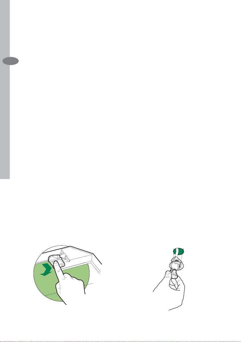
Keyboard lock: it is possible to jam the keyboard when, for example, cleaning the
glass. The motor and lights are switched off.By pressing the F-key (Delay) for about
5 seconds the keyboard block can be activated or de-activated. This function is
confi rmed by a Beep and by moving motor LEDS on display.
Page 43

MAINTENANCE
Remote Control (Optional)
The appliance can be controlled using a
remote control powered by a 1.5 V carbon-zinc alkaline batteries of the standard LR03-AAA type.
• Do not place the remote control near
to heat sources.
• Used batteries must be disposed of in
the proper manner.
Cleaning the Comfort Panels
• Pull the Comfort Panel to open it.
• Disconnect the panel from the hood
canopy by sliding the fi xing pin lever.
• The comfort panel must never be
washed in a dishwasher.
• Clean the outside using a damp cloth
and neutral liquid detergent.
• Clean the inside as well using a damp
cloth and neutral detergent; do not
use wet cloths or sponges, or jets
of water; do not use abrasive substances.
• When the above operation has been
completed, hook the panel back to
the hood canopy and close it by turning the knob in the opposite direction.
Maintenance electrolux 43
EN
Page 44

44 electrolux Maintenance
Cleaning of the Metal Cassette
Filters
Metal fi lters can be washed also in
a dish machine. They need to be
EN
washed every time a drop-symbol
ap-pears in the display or at least
every two months. In ca-se of very
frequent use these have to be washed even more often.
Alarm reset
• Press the G-key for at least 2 seconds.
Cleaning
• Open the comfort panel.
• Remove the fi lters one by one by
pushing them backwards and pulling
them down contemporane-ously.
• Wash the fi lters. Pay attention not to
bend them. Make sure that fi lters are
completely dry before put-ting them
into their seat. (a possible modifi cation
of the fi lter surface doesn’t infl uence
its effi ciency).
• Place the fi lters again into their seats
and make sure that the handle of the
fi lter remains outside.
• Close the comfort panel.
ATTENTION: Remove the fi lters one
by one pushing them towards the back
side of the hood and simultane-ously
pulling downwards and towards the
centre of the hood (only in case of 60
cm hood version).
Page 45

Maintenance electrolux 45
Replacing the Charcoal Filter
This fi lter cannot be washed or regene-
rated. It must be replaced when the C
appears on the display or at least once
every 4 months. The fi lter saturation
alarm has to be activated already before.
Enabling/Disabling the alarm signal
• In the recycling version hoods the fi l-
ter saturation alarm must be activated
during the instal-lation or later.
• Switch off the hood and the lights.
• Press the E-key for about 5 seconds
until the last two segments of the motor LEDS are lit on the display.
• By releasing the E-key the clock icon
starts to fl ash.
• Within 3 seconds press the D-key to
activate/deactivate charcoal fi lter sa-
turation alarm.
• C-symbol lit - charcoal fi lter satura-
tion alarm ACTIVATED.
• C-symbol unlit - charcoal fi lter satu-
ration alarm DEACTIVATED.
Reset the alarm signal
• Switch off the motor and the lighting
system.
• Press the G-key for at least 2 seconds.
EN
Replace the Filter
• Close the suction panel.
• Remove the metal grease fi lters.
• Remove the saturated charcoal fi lter,
turning the fasteners provided.
• Fit the new fi lter and fasten it its cor-
rect position.
• Put the metal grease fi lters in their
seats.
• Close the suction panel.
Light replacement
20 W halogen light.
• Remove the 2 screws fi xing the Ligh-
ting support, and pull it out of from the
Hood.
• Extract the lamp from the Support.
• Replace with another of the same
type, making sure that the two pins
are properly inserted in the lamp holder socket holes.
• Replace the Support, fi xing it in place
with the two screws removed as above.
Page 46

Page 47

Page 48

www.electrolux.com
436004187_02 - 080429
 Loading...