

Page 1
User Manual
EFC 929
GB
Page 2
Contents
Safety instructions ................................................................2
Description of the cooker hood ............................................3
Using the cooker hood .........................................................3
Maintenance and cleaning ................................................... 4
If the hood does not function ...............................................5
Technical data ......................................................................5
Installation ...........................................................................5
Safety instructions
The cooker hood may only be used in a private household and for normal cooking purposes. It fulfils international safety
regulations and standards of quality. All precautionary measures however cannot fully eliminate all the accident risks.
Therefore you should read through instructions, advises and safety instructions carefully before you install and start using
the cooker hood. Pay special attention to sentences with a warning triangle to avoid damages to person or property. Save
the instruction boook for future reference if the cooker hood is sold or left to another person.
Installation and service
• Any electrical installation of the cooker hood must be
carried out by a qualified electrician and the hood itself
must be installed by someone with experience.
Installation made by an unqualified person can lead to
loss of function of the cooker hood and possible damage
to person and/or property.
• The cooker hood must be at least 50 cm above electric
burners or electric range, or at least 75 cm above gas
burners or gas range.
• Ensure that the power cord does not get squeezed at the
installation.
• The cooker hood is only dead when the plug or the fuse
is disconnected.
• The cooker hood cannot be connected to flues of other
appliances that run on energy sources other than
electricity. Please, keep to the provisions of official
directives regarding the question of fumes discharge.
Use of cooker hood
• Never leave any deep-frying, melting fat, paraffin or
• Never do any flambé cooking underneath the cooker
• It is essential that the grease filter is regularly
Disposal
• Prevent accidents when disposing your cooker hood.
.
any other inflammable unattended on the hob. If
event of fire: Immediately switch off the cooker
hood and the cooker. Note! Cover the fire. Never use
water.
hood. It can cause a fire. Remember that overheated
fat may spontaneously ignite. Never leave the
fraying pan unattended.
cleaned to avoid fat to drip on to the hot zone and
cause fire. Read also the part “Maintenance and
Cleaning” in the instruction book.
Disconnect the power plug from the wall socket and
cut the power cord at the hood inlet. Contact your
local authority for information on where to dispose
the cooker hood.
2
Page 3
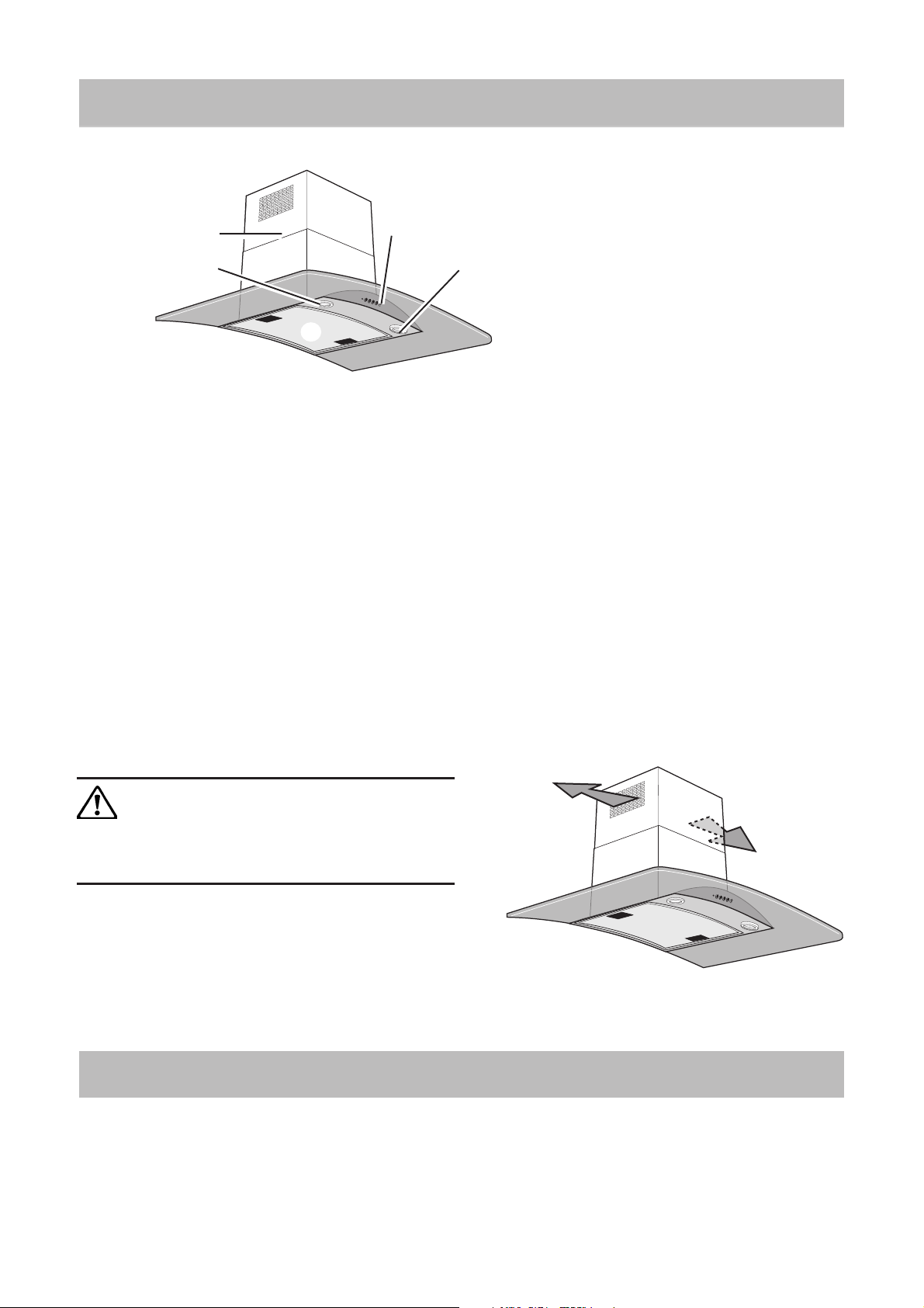
Description of the cooker hood
The cooker hood
1 Control panel
2 Grease filter
3 Lamp
4 Chimney
Fig. 1
4
3
2
Accessories
The following are included with the cooker hood (Fig. 1):
• Screws for mounting
• Template
• Non return fume valve (mounted in the outlet hole)
1
3
Functions
There are two possible systems:
• Extraction of air to outside using optional venting kit
and evacuation duct
• Recirculation using carbon filter.
Exhausting version
The air is vented outdoors by a 150 mm duct which must be
connected to connecting ring with no return valve on top of
the motor package.
The cooker hood cannot be connected to flues of
other appliances that run on energy sources other
than electricity. Please, keep to the provisions of
official directives regarding the question of fumes
discharge.
Recycling version
The air is filtered through a carbon filter and recirculated
into the room through the top sides of the chimney (Fig. 2).
This version is used when there is no exhaust duct for
venting outdoors or when it is impossible to install one.
Fig. 2
Special accessories
Carbon filter
When the hood is used in recirculation mode an active
carbon filter should be used.
Order by the retailer
PNC 942 120 182
3
Page 4

Using the cooker hood
The hood is fitted with a variable speed motor. The most effective use of the hood is obtained by switching it on a few
minutes before you start cooking and leaving it on a for approximately 15 minutes after you have finished, thus ensuring
all cooking odours are eliminated. The control switches are located on the unit’s front side:
• Indicator light (LED): this LED indicates when a speed is selected.
• Light switch: this switch is used to turn the light fitted in the hood on and off.
• Extractor fan switch: used to turn the fan off.
• Push-button 1: used to set the fan to speed 1.
• Push-button 2: used to set the fan to speed 2.
• Push-button 3: used to set the fan to speed 3.
Extractor fan
switch
Indicator light
Light switch
O123
Push-button 1
Correct ventilation
If the cooker hood should be working correctly there must
be an underpressure in the kitchen. It is important to keep
the kitchen windows closed and have a window in an
adjacent room open.
Important to know
Not applicable for recirculation. Great care must be taken if
the hood is used at the same time as a burner or fireplace
(e.g. gas, diesel, coal or wood heaters, water heaters, etc.), as
the hood will expel air which is required by these other
appliances. Attend to it by opening a window. The negative
pressure in the room must not exceed 0,04 mbar to prevent
fumes being drawn back into the room by the cooker hood.
Push-button 2
Push-button 3
4
Page 5

Maintenance and cleaning
Before doing any maintenance work on the hood,
disconnect it from the main supply by
disconnecting the plug from the wall socket or
unscrewing the fuse.
Cleaning the hood
Clean the outside of the hood using a damp cloth and a
mild detergent. Never use corrosive, abrasive or flammable
cleaning products.
Cleaning the grease filters
Clean the filter every month or every other month according
to how much the hood is used. The cleaner the filters, the
better it collects grease. Remove the filter by (Fig. 3):
• Push the handles towards the centre of the hood
• Pull the filter down to remove.
The filter is made of aluminium wires on which the grease
collects. Clean the filter in hot water using a detergent, or in
a dishwasher. Let the filter dry before putting it back. Note
that a dishwasher may discolour the filter.
Mounting the carbon filter
Only applicable for recirculation. The carbon filters absorb
smells and odours.
The carbon filter cannot be washed nor regenerated.
The carbon filter should be replaced every 6 months under
normal use.
Ask the technical assistance service or manufacturing
company for a new one.
After approximately three years of use, the KF2000 filter
should be replaced with a new, as the odour reduction capacity
will be reduced.
Mounting the carbon filter (Fig. 2):
• Unplug the unit or disconnect it from the power supply
• Remove the metal grease filter. Fig. 3
• Fit the carbon filter and fix it to the body of the hood
with two supplied screws. Fig. 4.
• Refit the metal grease filters.
To dismount proceed in reverse order.
Clean the filter regularly. The grease that
collects in the filter and the duct could ignite
if a hot plate is left on (or if overheating
occurs).
Fig. 3
Fig. 4
Changing the light
Disconnect the cooker hood from the main supply before
changing the light.
• Unscrew the light shield
• Replace the damaged lamp with a new lamp of the same
kind and rating. Fig. 5.
• Screw in place the light shield.
• If the lighting does not work properly, check that the
bulbs have been mounted properly into place before
contacting your nearest service centre!
20Watt - 12 Volts
Fig. 5
5
Page 6

If the hood does not function
Before calling for service
Check the plug is correctly connected to the wall socket.
Check the fuse. Do not attempt any repairs yourself that are
likely to lead to further damage. If the problem remains,
contact your dealer or an approved service company.
Remember to save your purchase receipt and warranty card
(only used in some countries).
Service and spare parts
Your dealer or service company will supply you with service
and spare parts. Be sure you have the product number and
model name at hand when ordering service or parts.
Technical data
Model EFC 929 X
Size Height 789-1094 mm
Width 898 mm
Depth 500 mm
Light Max 2x20 W
Grease filter 1 pcs.
Voltage 230 V
Total power 240 W
Installation
Unpacking
Check that the cooker hood is not damaged. Transportation
damages should immediately be reported to the transport
company. Damages, faults and eventually missing parts
should immediately be reported to the retailer. Dispose
carefully of the packaging material so that it is out of the
way of small children.
Electrical connection
The electric outlet should be placed inside the chimney. The
hood has a power cord and moulded plug with earth
connection for a wall outlet of 230V.
Position
The cooker hood should be mounted freely hanging on the
wall. The cooker hood must be at least 50 cm above electric
burners or electric range, or at least 75 cm above gas
burners or gas range.
6
Page 7

Mounting the cooker hood - Fig. 6
Preliminary information for installation of the hood:
Disconnect the hood during electrical connection, by turning the home mains switch off.
• Using a pencil, draw a line on the wall, extending up to the ceiling, to mark the centre. This will facilitate installation.
• Rest the drilling template against the wall (1) : the vertical centre line printed on the drilling template must
correspond to the centre line drawn on the wall, and the bottom edge of the drilling template must correspond to the
bottom edge of the hood: bear in mind that, when installation is complete, the underside of the hood must be at least
60 cm above the cooker top in the case of electric cookers, and at least 75 cm above the cooker top in the case of gas
or mixed cookers.
• Mark the two holes and drill them (2), remove the drilling template, insert 2 wall plugs (3) , hooks (4) and fix them
with screws (5).
• Hang the hood on the hooks (6).
• Adjust the distance of the hood from the wall, adjust the horizontal position of the hood (7).
• From inside the suction unit, use a pencil to mark the 2 holes to be used for final fixing of the hood (8).
• Remove the hood from the bracket.
• Drill at the point marked (2 x Ø8mm ) and insert 2 wall plugs (9).
• Hook the hood onto the bottom bracket.
• Fix the hood into its final position on the wall using 2 x 5x45mm screw (10 - ABSOLUTELY ESSENTIAL).
• Rest the chimney support bracket (13) against the wall, touching the ceiling. Use the support bracket as a drilling
template (the small slot formed on the support must coincide with the line drawn on the wall as above) and mark 2
holes with a pencil, dril the holes (11 - Ø8mm), insert 2 wall plugs (12).
• Fix the chimney support bracket to the wall using two 5x45mm screws (14).
• Connect a pipe (pipe and pipe clamps not provided, to be purchased separately) for discharge of fumes to the
connection ring located over the suction motor unit (16).
If the hood is to be used in ducting version, the other end of the pipe must be connected to a device expelling the
fumes to the outside. If the
hood is to be used in filter
version, fix deflector (15F)
to the chimney support
bracket using 2 screws,
and connect the other end
of the pipe to the
connection ring on
deflector.
• Make the electrical
connections.
• Apply the chimney stacks
and fasten them at the top
to the chimney support
using 2 screws (17).
• Slide the bottom section
of the chimney down until
it completely covers the
suction unit and slots into
the housing provided on
top of the hood (18).
(Ø 8mm) 11
12
11 (Ø 8mm)
13
14
14
12
17
16
7
6
15F
17
18
Fig. 6
2
3
9 (Ø 8mm)
5
4
3
2
5
4
9 (Ø 8mm)
1
10
10
8
7
Page 8

LI1RDA Ed.06/01
 Loading...