

Page 1
User Manual
EFC 928
GB
Page 2
Contents
Safety instructions ................................................................2
Description of the cooker hood ............................................3
Using the cooker hood .........................................................3
Maintenance and cleaning ................................................... 4
If the hood does not function ...............................................5
Technical data ......................................................................5
Installation ...........................................................................5
Safety instructions
The cooker hood may only be used in a private household and for normal cooking purposes. It fulfils international safety
regulations and standards of quality. All precautionary measures however cannot fully eliminate all the accident risks.
Therefore you should read through instructions, advises and safety instructions carefully before you install and start using
the cooker hood. Pay special attention to sentences with a warning triangle to avoid damages to person or property. Save
the instruction boook for future reference if the cooker hood is sold or left to another person.
Installation and service
• Any electrical installation of the cooker hood must be
carried out by a qualified electrician and the hood itself
must be installed by someone with experience.
Installation made by an unqualified person can lead to
loss of function of the cooker hood and possible damage
to person and/or property.
• The cooker hood must be at least 50 cm above electric
burners or electric range, or at least 75 cm above gas
burners or gas range.
• Ensure that the power cord does not get squeezed at the
installation.
• The cooker hood is only dead when the plug or the fuse
is disconnected.
• The cooker hood cannot be connected to flues of other
appliances that run on energy sources other than
electricity. Please, keep to the provisions of official
directives regarding the question of fumes discharge.
Use of cooker hood
• Never leave any deep-frying, melting fat, paraffin or
• Never do any flambé cooking underneath the cooker
• It is essential that the grease filter is regularly
Disposal
• Prevent accidents when disposing your cooker hood.
.
any other inflammable unattended on the hob. If
event of fire: Immediately switch off the cooker
hood and the cooker. Note! Cover the fire. Never use
water.
hood. It can cause a fire. Remember that overheated
fat may spontaneously ignite. Never leave the
fraying pan unattended.
cleaned to avoid fat to drip on to the hot zone and
cause fire. Read also the part “Maintenance and
Cleaning” in the instruction book.
Disconnect the power plug from the wall socket and
cut the power cord at the hood inlet. Contact your
local authority for information on where to dispose
the cooker hood.
2
Page 3
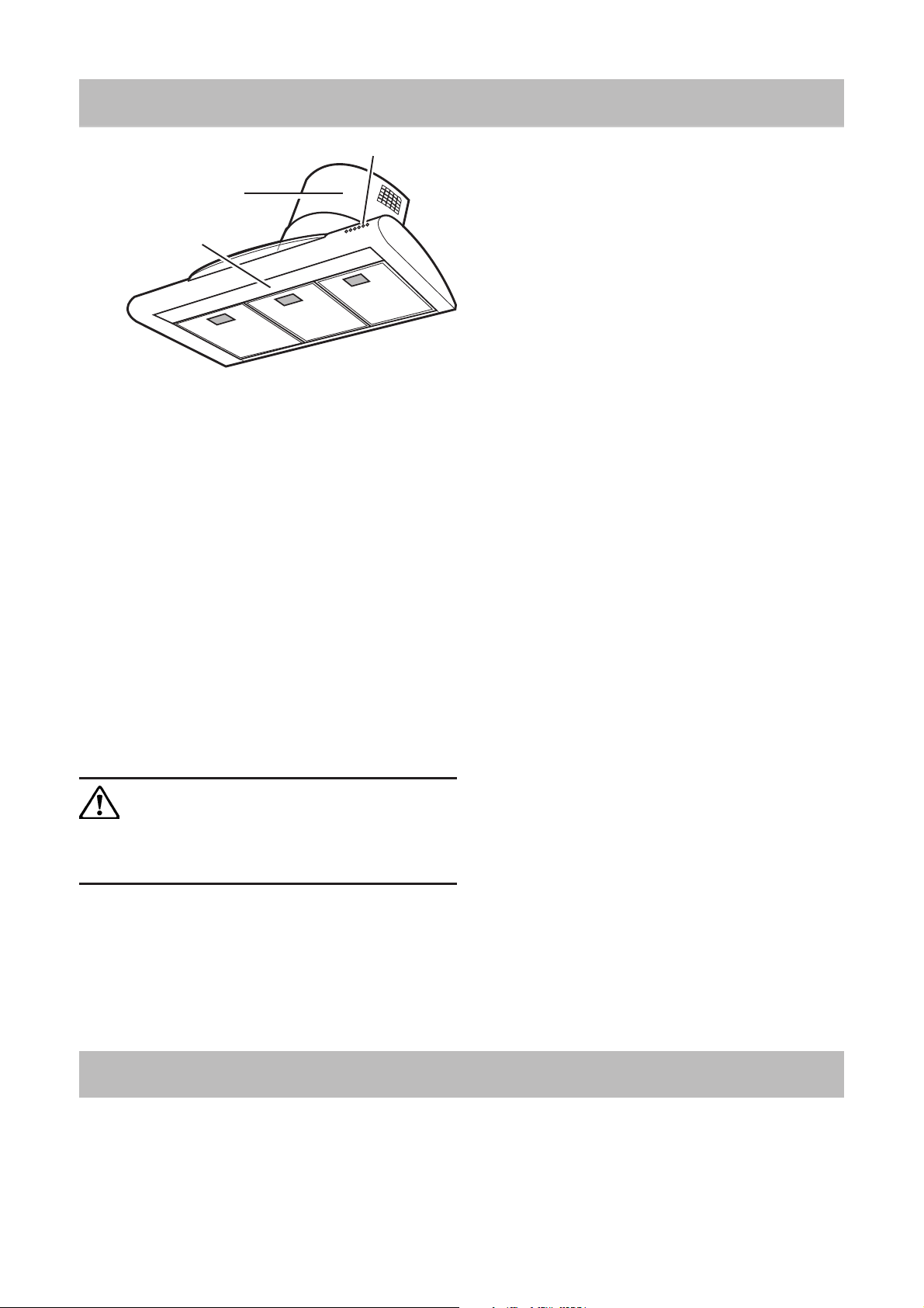
Description of the cooker hood
The cooker hood
1 Control panel
2 Grease filter
3 Lamp
4 Chimney
Fig. 1
4
3
2
2
1
2
Accessories
The following are included with the cooker hood (Fig. 1):
• Screws for mounting
• Template
• Non return fume valve (mounted in the outlet hole)
Functions
There are two possible systems:
• Extraction of air to outside using optional venting kit
and evacuation duct
• Recirculation using carbon filter.
Exhausting version
The air is vented outdoors by a 150 mm duct which must be
connected to connecting ring with no return valve on top of
the motor package.
The cooker hood cannot be connected to flues of
other appliances that run on energy sources other
than electricity. Please, keep to the provisions of
official directives regarding the question of fumes
discharge.
Recycling version
The air is filtered through a carbon filter and recirculated
into the room through the top sides of the chimney.
This version is used when there is no exhaust duct for
venting outdoors or when it is impossible to install one.
Special accessories
Active carbon filter
When the hood is used in recirculation mode an active
carbon filter should be used.
Order by the retailer
TYPE 23
3
Page 4
Using the cooker hood
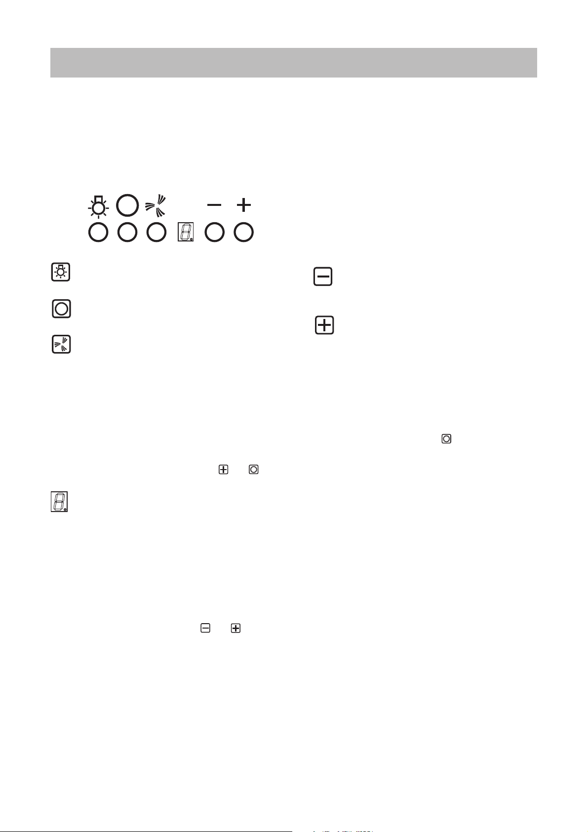
The control panel
Best results are obtained by using low speed for normal conditions and high speed when smells and steam are more
concentrated.
Turn the hood on a few minutes before you start cooking then you will get an underpressure in the kitchen. It should
be left on after cooking for about 15 minutes or until all steam and smells have disappeared.
The control panel is located on the front right side
= Lighting, on/off.
= Fan off
= Fast speed switch (P+ the led on the bottom
right side of the display flashes). This speed
should be used when the concentration of
cooking fumes or odours is particularly strong
(for example when frying, cooking fish etc.).
The fast speed will run for about 5 minutes
and then return to the speed previously set
automatically (1, 2 or 3), or switch off if no
speed was selected.
To turn off the fast speed, before the end of
the 5 minutes, press button and .
= Display showing fan speed (1-3-P), change
grease filters (grease filter saturation indicator
- F) and change activated carbon filters
(carbon filter saturation indicator - C).
A lighted Led on the right bottom side
indicates the hood is in stand-by
Warning!
The active carbon filter saturation function is
not activated.
In order to activate the carbon filter saturation
indicator, press buttons and
simultaneously for 3 seconds. Initially, only
letter F will fbe displayed, then after the 3
seconds have passed, letter C will be
displayed as well, indicating that the carbon
filter saturation control system is active.
To switch off the system, re-press the same
two buttons: letter C appear on display and
after 3 seconds letter it disappear and the
device will be switched off.
= Decrease fan speed button for reducing
speed of motor from 3 down to speed 1.
= Increase fan speed button for increasing
speed of motor from 1 to 3.
If the hood fails to operate correctly,
briefly disconnect it from the mains
power supply for almost 5 sec. by pulling
out the plug. Then plug it in again and
try once more before contacting the
Technical Assistance Service.
Always press the fan off button before disconnecting
the hood from the mains supply.
Correct ventilation
If the cooker hood should be working correctly there
must be an underpressure in the kitchen. It is important
to keep the kitchen windows closed and have a window
in an adjacent room open.
Important to know
Not applicable for recirculation. Great care must be
taken if the hood is used at the same time as a burner or
fireplace (e.g. gas, diesel, coal or wood heaters, water
heaters, etc.), as the hood will expel air which is
required by these other appliances. Attend to it by
opening a window. The negative pressure in the room
must not exceed 0,04 mbar to prevent fumes being
drawn back into the room by the cooker hood.
4
Page 5

Maintenance and cleaning
Before doing any maintenance work on the hood,
disconnect it from the main supply by
disconnecting the plug from the wall socket or
unscrewing the fuse.
Cleaning the hood
Clean the outside of the hood using a damp cloth and a
mild detergent. Never use corrosive, abrasive or flammable
cleaning products.
Cleaning the grease filters
Clean the filter every month or every other month according
to how much the hood is used. The cleaner the filters, the
better it collects grease. Remove the filter by (Fig. 2):
• Push the handle towards the rear of the hood (a).
• Pull the filter down at the front and remove it forwards
(b).
The filter is made of aluminium wires on which the grease
collects. Clean the filter in hot water using a detergent, or in
a dishwasher. Let the filter dry before putting it back. Note
that a dishwasher may discolour the filter.
Cleaning/replacing the carbon filter
Only applicable for recirculation. The carbon filters absorb
smells and odours.
Unlike other carbon filters, the TYPE 23 carbon filter can be
cleaned and reactivated. At normal use the filter should be
cleaned every second month. The best way to clean the filter
is in the dishwasher. Use normal detergent and choose the
highest temperature (65º C). Wash the filter separately so that
no food parts gets stuck on the filter and later causes bad odours.
To reactivate the carbon, the filter should be dried in an oven
for 10 minutes with a temperature of maximum 100ºC.
Clean the filter regularly. The grease that
collects in the filter and the duct could ignite
if a hot plate is left on (or if overheating
occurs).
a
b
Fig. 2
After approximately three years of use, the TYPE 23 filter
should be replaced with a new, as the odour reduction capacity
will be reduced.
Mounting the carbon filter (Fig. 2):
• Unplug the unit or disconnect it from the power supply
• Remove the metal grease filters. Fig. 1.
• Unscrew the two carbon filter frame screws and insert the
active carbon filter in the support.
• Re-close the carbon filter frame using the same screws.
• Refit the metal grease filters.
To dismount proceed in reverse order.
Changing the light
Disconnect the cooker hood from the main supply before
changing the light.
• Remove the metal grease filter. Fig. 1.
• Remove the screw holding the lamp shade and remove
the lamp shade itself. Fig. 4.
• Replace the old light bulb with a new light bulb of the
same kind.
• Replace and fix the lamp shade
• Replace the grease filters
Fig. 3
Fig. 4
• If the lighting does not work properly, check that the
bulbs have been fitted properly into place before
contacting your nearest service centre!
5
Page 6

If the hood does not function
Before calling for service
Check the plug is correctly connected to the wall socket.
Check the fuse. Do not attempt any repairs yourself that are
likely to lead to further damage. If the problem remains,
contact your dealer or an approved service company.
Remember to save your purchase receipt and warranty card
(only used in some countries).
Service and spare parts
Your dealer or service company will supply you with service
and spare parts. Be sure you have the product number and
model name at hand when ordering service or parts.
Technical data
Model EFC 928 X
Size Height 800-1340 mm
Width 898 mm
Depth 510 mm
Light Max 2x11 W
Grease filter 3 pcs.
Voltage 230 V
Total power 185 W
Installation
Unpacking
Check that the cooker hood is not damaged. Transportation
damages should immediately be reported to the transport
company. Damages, faults and eventually missing parts
should immediately be reported to the retailer. Dispose
carefully of the packaging material so that it is out of the
way of small children.
Electrical connection
The electric outlet should be placed inside the chimney. The
hood has a power cord and moulded plug with earth
connection for a wall outlet of 230V.
Position
The cooker hood should be mounted freely hanging on the
wall. The cooker hood must be at least 50 cm above electric
burners or electric range, or at least 75 cm above gas
burners or gas range.
6
Page 7

Mounting the cooker hood - Fig. 5
• Rest the template correctly against the wall. The lower
corner of the template corresponds to the lower corner of
the extractor hood. Fig. 3.
• A cross is marked on the template to indicate the centre.
Mark this point on the wall. Fig. 3.
• Drill two holes (Ø 8 mm) in the wall at the points
indicated, insert the stops (Ø 8 mm) and screw in the
hooks provided. Fig. 3.
• Hang the hood and adjust its position using the screws
on the hooks. Fig. 4.
• The reference point “a” marked on the body of the
extractor hood must coincide with the line you have
drawn on the wall. Fig. 4.
Fig. 6
• Once the extractor hood has been correctly aligned,
remove the grease filter.
• From inside the hood, mark the final points at which the
hood has to be fixed to the wall. Fig. 5.
(to reach these points it will be necessary to remove
activated carbon filter frame until the filter itself is
replaced - see Fig. 2).
• Remove the hood.
• Drill 2 holes (Ø 8 mm) and insert the plugs (Ø 8 mm).
Fig. 5.
• Hang the extractor hood up again.
• Fix the hood into its final position using 2 screws (Ø
5x45 mm). Fig. 5.
Fig. 7
Fig. 7
7
Page 8

• Remove the telescopic chimney support M by
unscrewing the side screws R (one on each side - these
screws must be kept). Fig. 6.
• Remove the air pipe L from the telescopic chimney
support M; to do this, unscrew the four screws (Ø 2,9 x
9,5 mm) fixing the air pipe to the support (these screws
must be kept). Fig. 6.
• Fit the telescopic chimney support to the wall, at a point
close to the ceiling. The telescopic chimney support has
a reference mark P, which must coincide with the line
that you have already drawn on the wall. Fig. 6.
• Using a pencil, mark the two holes required to fix the
support, and drill the holes (Ø 8 mm). Fig. 6.
• Insert two plugs and fix the telescopic chimney support
M using 2 screws size (5x45 mm). Fig. 6.
• During installation the plug must not be connected to
the power supply.
M
M
L
R
Select the hood operating mode
• Extractor operation
Fix the 150 mm diameter ABS pipe to the hood outlet
and ensure that the other end discharges into the open
air.
• Filter operation
If the connector ring has not yet been installed, it must
be fitted at this point (Q in Fig. 7, bayonet connector).
Turn it in a clockwise direction and fix it to the air pipe
L using a screw. Insert the air pipe into the telescopic
chimney support and fix it with four screws (Ø 2,9 x 9,5
mm). Fig. 7.
Fix the 150 mm diameter ABS pipe to the hood outlet,
and connect it to the air pipe connector ring.
P
R
R
R
Q
L
For both versions:
• The hood can now be connected to the power supply.
• If a gas non-return valve has been installed or is required,
ensure that it opens and closes properly.
• Fix the top part the telescopic outlet pipe to the relative
support, using the two 3 mm dia x 9 mm screws R. Fig. 6.
• Slide the bottom part of the telescopic outlet pipe
downward until it rests in its housing on the top of the
hood.
• Replace the grease filters.
8
Page 9

91011
Page 10

Page 11

Page 12

LI1REA Ed.06/01
 Loading...